Analyse de flambement d'assemblage acier
Le flambement n'est généralement pas un problème important dans les assemblages. Cependant, il convient de vérifier qu'il n'y a pas de problèmes de flambement et que les résultats de l'analyse de résistance, qui utilise uniquement une analyse géométriquement linéaire, sont corrects.
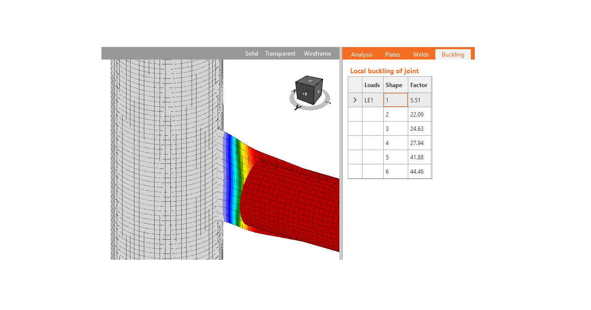
IDEA StatiCa Connection peut effectuer une analyse linéaire de flambement d'un modèle d'assemblage. Les résultats sont présentés sous forme de modes de flambement. La charge critique, à laquelle le flambement du modèle parfait se produit, est calculée pour chaque mode de flambement. La charge critique est présentée par des multiplicateurs de la charge appliquée à l'assemblage. En fonction du mode de flambement et du multiplicateur de charge critique, l'utilisateur peut déterminer la conception sûre au flambement.
Certaines normes, par exemple l'Eurocode (EN 1993-1-1, Chapitre 5.2.1), recommandent un multiplicateur de charge critique supérieur à 15 pour les modèles à barres des structures. Si le multiplicateur de charge critique est supérieur à 15, la norme n'exige pas de vérification normative du flambement des éléments.
Pour les assemblages, la situation est différente et la norme ne fournit aucune recommandation spécifique. La conception du flambement local doit être abordée d'une autre manière. En général, le flambement local peut être divisé en trois groupes :
- Plaques reliant les éléments individuels
- Plaques de raidissement dans l'assemblage – raidisseurs, nervures, jarrets courts
- Sections fermées et sections à parois minces
Le flambement des plaques du groupe 1 affecte la forme de flambement de l'ensemble de l'élément. Il est donc recommandé d'appliquer les mêmes règles que pour ces éléments également à ces plaques, c'est-à-dire de considérer un multiplicateur de charge critique sûr de 15 et plus. L'ingénieur doit vérifier que l'exécution réelle de l'assemblage correspond aux conditions aux limites du modèle utilisé pour l'analyse de flambement de la structure entière.
Les plaques du groupe 2 affectent le flambement local de l'assemblage. Pour ces plaques, la limite sûre du multiplicateur de charge critique de 15 est conservative, mais des recommandations spécifiques font défaut dans les normes. Des recommandations sont fournies par des publications de recherche qui recommandent une limite sûre du multiplicateur de charge critique égale à 3.
Le flambement des plaques et des éléments du groupe 3 est très problématique, et une évaluation individuelle de chaque cas particulier est nécessaire.
Pour les plaques dont le multiplicateur de charge critique est inférieur aux valeurs suggérées (15 pour le groupe 1, 3 pour le groupe 2), la conception plastique ne peut pas être utilisée. Dans ce cas, d'autres méthodes sont nécessaires pour concevoir l'assemblage :
- Vérification normative selon la norme de calcul applicable, par exemple l'Eurocode ou la Spécification AISC ou le Manuel de conception
- Méthode générale selon EN 1993-1-5 Annexe B – Éléments non uniformes où les résultats de l'AMN et de l'ALB sont utilisés pour déterminer la résistance au flambement des plaques élancées
- Analyse géométriquement et matériellement non linéaire avec imperfections disponible dans l'application IDEA StatiCa Member
Le résultat de l'analyse linéaire de flambement dans IDEA StatiCa Connection n'est pas une vérification normative définitive. Les normes ne fournissent pas de recommandations suffisantes. L'évaluation requiert le jugement de l'ingénieur et IDEA StatiCa fournit des outils uniques non disponibles dans les logiciels de conception standard.
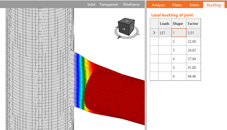
Gousset comme prolongement d'un treillis – exemple de plaque du groupe 1 pour laquelle le flambement peut être négligé si le facteur de flambement critique est supérieur à 15
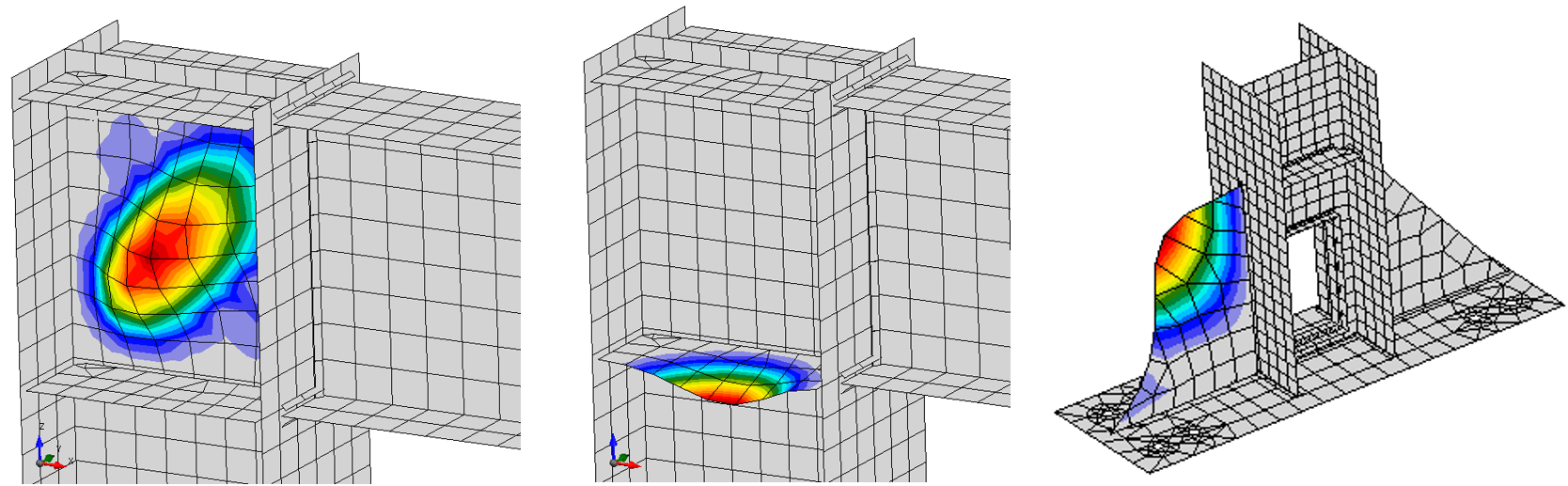
Exemples de formes de flambement de plaques du groupe 2 pour lesquelles le flambement peut être négligé si le facteur de flambement critique est supérieur à 3
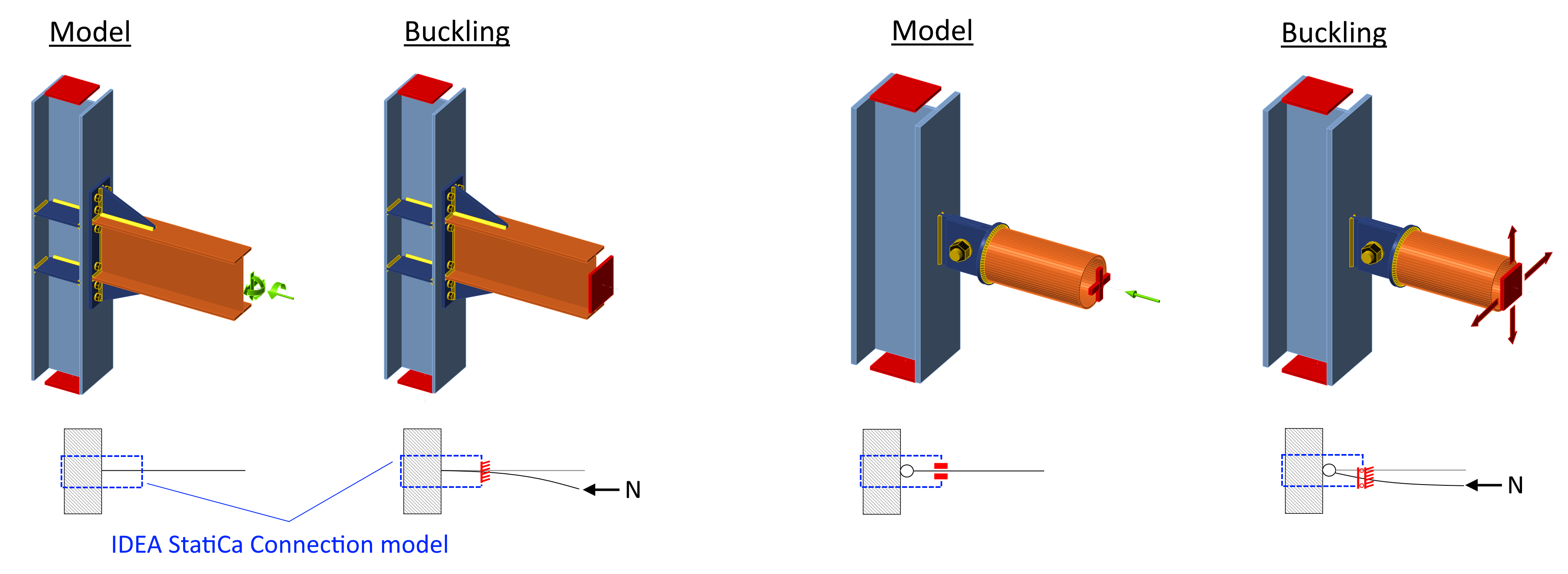
Le modèle utilisé pour l'analyse de flambement est supporté par des appuis différents de ceux définis par l'utilisateur dans le type d'analyse contrainte-déformation (EPS). L'élément porteur reste entièrement supporté. Le type de modèle d'une poutre défini comme N-Vy-Vz-Mx-My-Mz (libre de se déplacer dans le type d'analyse contrainte-déformation) est entièrement supporté dans l'analyse de flambement. Tous les autres types d'analyse de poutre ont les moments fléchissants et l'effort normal bloqués, mais sont libres de se déplacer latéralement.
- Type de modèle N-Vy-Vz-Mx-My-Mz : appuis dans le modèle de flambement : N-Vy-Vz-Mx-My-Mz
- Type de modèle N-Vy-Vz : appuis dans le modèle de flambement : N-Mx-My-Mz
- Type de modèle N-Vz-My : appuis dans le modèle de flambement : N-Mx-My-Mz
- Type de modèle N-Vy-Mz : appuis dans le modèle de flambement : N-Mx-My-Mz
Il est supposé que dans le cas d'un assemblage rigide, l'utilisateur impose le moment fléchissant et que le flambement du segment de poutre court n'est pas pertinent. En revanche, dans le cas de l'assemblage articulé, l'utilisateur impose uniquement l'effort normal et l'effort tranchant sans moment fléchissant, mais le flambement de l'élément articulé est pertinent et contribue donc au facteur de flambement. Voir la figure ci-dessous. « Modèle » montre le modèle dans le type d'analyse contrainte-déformation, et « Flambement » montre le modèle dans l'analyse de flambement.