IDEA StatiCa Detail – Diseño estructural de discontinuidades de hormigón
El fundamento teórico se basa en COMPATIBLE STRESS FIELD DESIGN OF STRUCTURAL CONCRETE
(Kaufmann et al., 2020)
Diseño estructural de discontinuidades de hormigón en IDEA StatiCa Detail
1 Introducción al método CSFM
1.1 Introducción general al diseño estructural de detalles de hormigón
1.2 Hipótesis principales y limitaciones
1.3 Herramientas de diseño para la armadura
2 Modelo de análisis de IDEA StatiCa Detail
2.1 Introducción a la implementación de elementos finitos
2.2 Apoyos y componentes de transmisión de cargas
2.3 Transferencia de carga en extremos recortados de vigas
2.4 Modificación geométrica de secciones transversales
2.5 Tipos de elementos finitos
2.6 Mallado
2.7 Método de resolución y algoritmo de control de carga
2.8 Presentación de resultados
3 Verificación del modelo
3.1 Estados límite, cálculo de la anchura de fisura y rigidización a tracción
4 Verificaciones estructurales según EUROCÓDIGO
4.1 Modelos de material (EN)
4.2 Coeficientes de seguridad
4.3 Análisis en estado límite último
4.4 Áreas parcialmente cargadas (APC)
4.5 Análisis en estado límite de servicio
5 Verificaciones estructurales según ACI 318-19
5.1 Modelos de material (ACI)
5.2 Factores de reducción de resistencia y de carga
5.3 Verificaciones de resistencia
5.4 Zonas de apoyo y anclaje - Áreas parcialmente cargadas
5.5 Verificaciones en servicio
6 Verificaciones estructurales según AASHTO
6.1 Modelos de material (AASHTO)
6.2 Factores de resistencia y de carga
6.3 Estado límite de resistencia
6.4 Resistencia en zonas de apoyo y anclaje – Áreas parcialmente cargadas
6.5 Estado límite de servicio
7 Verificaciones estructurales según AS 3600
7.1 Modelos de material (AUS)
7.2 Factores de reducción de tensión y de carga
7.3 Verificaciones de resistencia y anclaje
7.4 Verificaciones en servicio
8 Pretensado en Detail - Descripción del modelo
1 Introducción al método CSFM
1.1 Introducción general al diseño estructural de detalles de hormigón
El diseño y la evaluación de elementos de hormigón se realizan normalmente a nivel seccional (elemento 1D) o puntual (elemento 2D). Este procedimiento está descrito en todas las normativas de diseño estructural, por ejemplo, en (EN 1992-1-1 o ACI 318-19), y se utiliza en la práctica habitual de la ingeniería estructural. Sin embargo, no siempre se conoce o se respeta que el procedimiento solo es aceptable en zonas donde se aplica la hipótesis de Bernoulli-Navier de distribución plana de deformaciones (denominadas regiones B). Los lugares donde esta hipótesis no se aplica se denominan regiones de discontinuidad o perturbadas (regiones D). En la (Fig. 1) se muestran ejemplos de regiones B y D en elementos 1D. Estas son, por ejemplo, zonas de apoyo, partes donde se aplican cargas concentradas, ubicaciones donde se produce un cambio brusco en la sección transversal, aberturas, etc. Al diseñar estructuras de hormigón, encontramos muchas otras regiones D, como muros, diafragmas de puentes, ménsulas, etc.
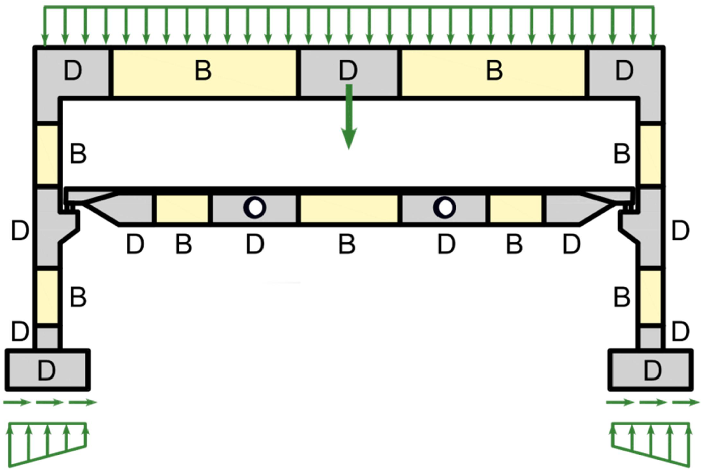
\[ \textsf{\textit{\footnotesize{Fig. 1\qquad Discontinuity regions (Navrátil et al. 2017)}}}\]
En el pasado, se utilizaban reglas de diseño semiempíricas para dimensionar las regiones de discontinuidad. Afortunadamente, estas reglas han sido ampliamente superadas en las últimas décadas por los modelos de biela-y-tirante (Schlaich et al., 1987) y los campos de tensiones (Marti 1985), que están recogidos en los códigos de diseño actuales y son utilizados frecuentemente por los proyectistas hoy en día. Estos modelos son herramientas mecánicamente coherentes y potentes. Cabe señalar que los campos de tensiones pueden ser en general continuos o discontinuos, y que los modelos de biela-y-tirante son un caso especial de campos de tensiones discontinuos.
A pesar de la evolución de las herramientas de cálculo en las últimas décadas, los modelos Biela-y-tirante se siguen utilizando esencialmente como cálculos manuales. Su aplicación en estructuras reales es tediosa y consume mucho tiempo, ya que se requieren iteraciones y es necesario considerar varios casos de carga. Además, este método no es adecuado para verificar criterios de servicio (deformaciones, anchos de fisura, etc.).
El interés de los ingenieros estructurales en una herramienta fiable y rápida para diseñar regiones D llevó a la decisión de desarrollar el nuevo Método del Campo de Tensiones Compatible, un método para el diseño asistido por ordenador de campos de tensiones que permite el diseño y la evaluación automáticos de elementos de hormigón estructural sometidos a cargas en su plano.
El Método del Campo de Tensiones Compatible (CSFM) es un método continuo de análisis de campos de tensiones basado en elementos finitos, en el que las soluciones clásicas de campos de tensiones se complementan con consideraciones cinemáticas, es decir, se evalúa el estado de deformación en toda la estructura. De este modo, la resistencia a compresión efectiva del hormigón puede calcularse automáticamente en función del estado de deformación transversal, de manera similar a los análisis de campo de compresión que tienen en cuenta el ablandamiento a compresión (Vecchio y Collins 1986; Kaufmann y Marti 1998) y el método EPSF (Fernández Ruiz y Muttoni 2007). Además, el CSFM considera la rigidización a tracción, proporcionando rigideces realistas a los elementos, y cubre todas las prescripciones de los códigos de diseño (incluidos los aspectos de servicio y capacidad de deformación) que los enfoques anteriores no abordaban de forma coherente. El CSFM utiliza las leyes constitutivas uniaxiales habituales proporcionadas por las normativas de diseño para el hormigón y la armadura. Estas son conocidas en la fase de diseño, lo que permite utilizar el método de los coeficientes parciales de seguridad. Por tanto, los proyectistas no tienen que proporcionar propiedades de material adicionales, a menudo arbitrarias, como las que normalmente se requieren para los análisis no lineales de elementos finitos, lo que hace que el método sea perfectamente adecuado para la práctica de la ingeniería.
Para fomentar el uso de campos de tensiones asistidos por ordenador por parte de los ingenieros estructurales, estos métodos deben implementarse en entornos de software fáciles de usar. Con este fin, el CSFM ha sido implementado en IDEA StatiCa Detail; un nuevo software comercial fácil de usar desarrollado conjuntamente por la ETH Zúrich y la empresa de software IDEA StatiCa en el marco del proyecto DR-Design Eurostars-10571.
1.2 Principales supuestos y limitaciones del CSFM en 2D
El CSFM considera la tensión principal máxima del hormigón en compresión (σc2r) y las tensiones de la armadura (σsr) en las fisuras, despreciando la resistencia a tracción del hormigón (σc1r = 0), excepto por su efecto de rigidización sobre la armadura. La consideración de la rigidización a tracción permite simular las deformaciones medias de la armadura (εm). Se consideran fisuras ficticias, giratorias y sin tensiones que se abren sin deslizamiento (Fig. 2a), y también se tiene en cuenta el equilibrio en las fisuras junto con las deformaciones medias de la armadura.
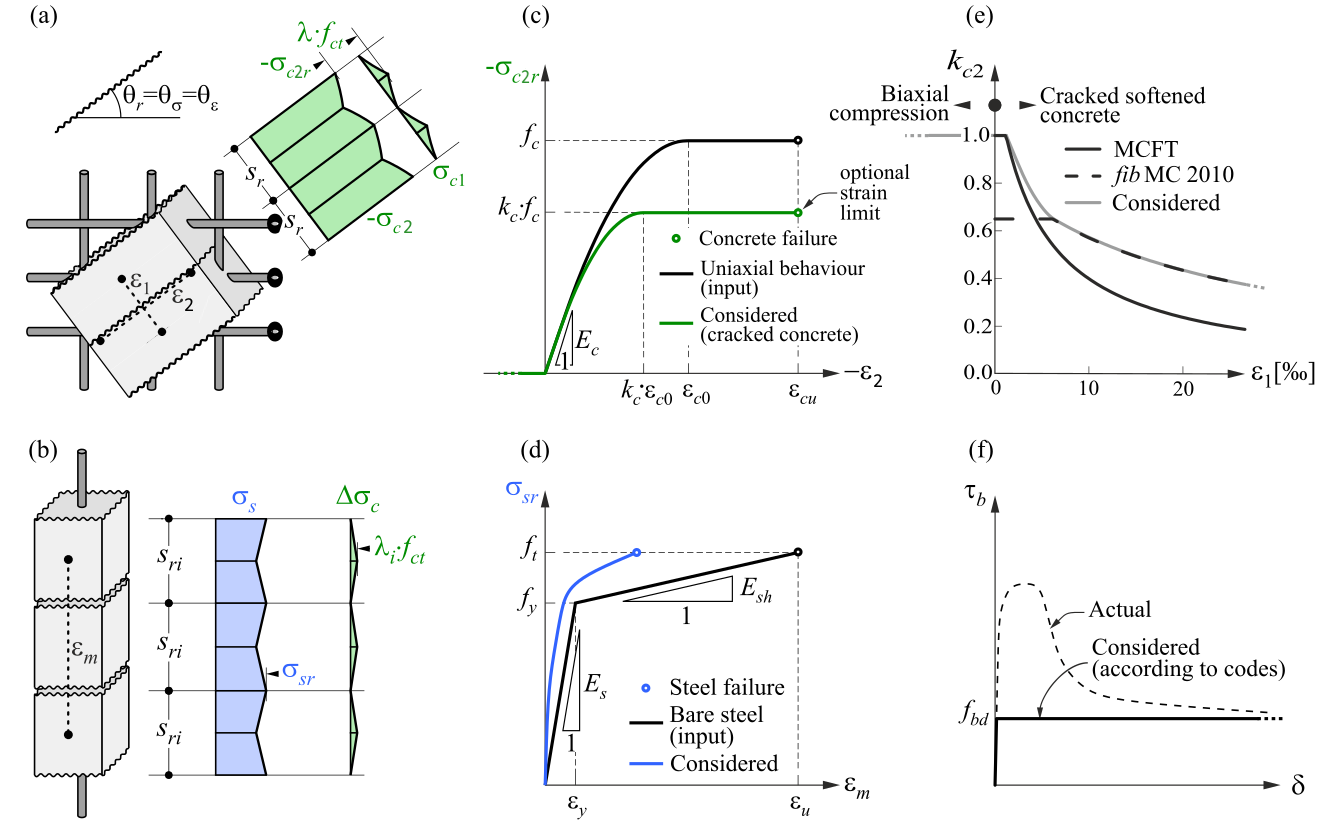
\( \textsf{\textit{\footnotesize{Fig. 2\qquad Basic assumptions of the CSFM: (a) principal stresses in concrete; (b) stresses in the reinforcement direction;}}}\) \( \textsf{\textit{\footnotesize{(c) stress-strain diagram of concrete in terms of maximum stresses with consideration of compression softening;}}}\) \( \textsf{\textit{\footnotesize{(d) stress-strain diagram of reinforcement in terms of stresses at cracks and average strains; (e) compression softening}}}\) \( \textsf{\textit{\footnotesize{law; (f) bond shear stress-slip relationship for anchorage length verifications.}}}\)
A pesar de su simplicidad, se ha demostrado que supuestos similares proporcionan predicciones precisas para elementos de hormigón armado sometidos a cargas en su plano (Kaufmann 1998; Kaufmann y Marti 1998), siempre que la armadura dispuesta evite fallos frágiles en la fisuración. Además, la no consideración de ninguna contribución de la resistencia a tracción del hormigón a la carga última es coherente con los principios de los códigos de diseño modernos, que se basan principalmente en la teoría de la plasticidad.
Sin embargo, el CSFM no es adecuado para elementos esbeltos sin armadura transversal, ya que se ignoran los mecanismos relevantes para dichos elementos, como el engranamiento de áridos, las tensiones residuales de tracción en el extremo de la fisura y el efecto pasador, todos ellos dependientes directa o indirectamente de la resistencia a tracción del hormigón. Aunque algunas normas de diseño permiten el dimensionamiento de estos elementos mediante disposiciones semiempíricas, el CSFM no está concebido para este tipo de estructuras potencialmente frágiles.
Hormigón
El modelo de hormigón implementado en el CSFM se basa en las leyes constitutivas uniaxiales de compresión prescritas por los códigos de diseño para el dimensionamiento de secciones transversales, que dependen únicamente de la resistencia a compresión. El diagrama parábola-rectángulo (Fig. 2c) se utiliza por defecto en el CSFM, aunque los proyectistas también pueden optar por una relación elástica-plástica perfecta más simplificada. Al verificar según el código ACI, solo es posible utilizar el diagrama tensión-deformación parábola-rectángulo. Como se ha mencionado anteriormente, la resistencia a tracción se desprecia, al igual que en el diseño clásico de hormigón armado.
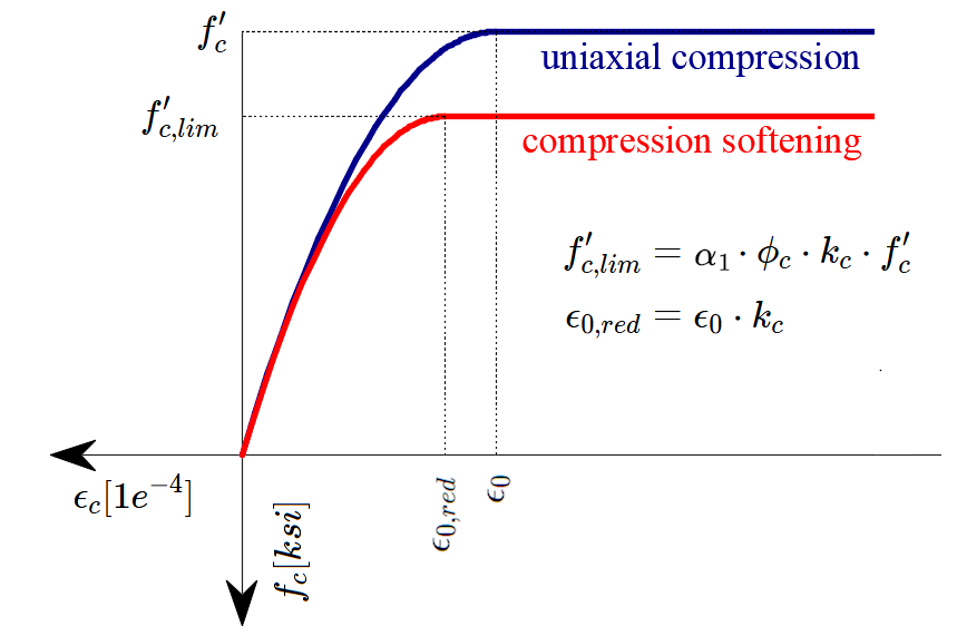
La resistencia a compresión efectiva se evalúa automáticamente para el hormigón fisurado en función de la deformación principal de tracción (ε1) mediante el factor de reducción kc2, tal como se muestra en las Fig. 2c y 2e. La relación de reducción implementada (Fig. 2e) es una generalización de la propuesta del fib Model Code 2010 para verificaciones a cortante, que contiene un valor límite de 0,65 para la relación máxima entre la resistencia efectiva del hormigón y la resistencia a compresión del hormigón, que no es aplicable a otros casos de carga.
El CSFM en IDEA StatiCa Detail no considera un criterio de fallo explícito en términos de deformaciones para el hormigón en compresión (es decir, considera una rama infinitamente plástica tras alcanzar la tensión máxima). Esta simplificación no permite verificar la capacidad de deformación de las estructuras que fallan por compresión. Sin embargo, su capacidad última se predice correctamente cuando, además del factor del hormigón fisurado (kc2) definido en (Fig. 2e), se considera el aumento de la fragilidad del hormigón al incrementarse su resistencia mediante el factor de reducción \( \eta_{fc} \) definido en el fib Model Code 2010 de la siguiente manera:
\[f_{c,red} = k_c \cdot f_{c} = \eta _{fc} \cdot k_{c2} \cdot f_{c}\]
\[{\eta _{fc}} = {\left( {\frac{{30}}{{{f_{c}}}}} \right)^{\frac{1}{3}}} \le 1\]
donde:
kc es el factor de reducción global de la resistencia a compresión
kc2 es el factor de reducción debido a la presencia de fisuración transversal
fc es la resistencia característica del hormigón en probeta cilíndrica (en MPa para la definición de \( \eta_{fc} \)).
También existe una reducción del factor kc2 por razones de estabilidad del cálculo. Esta reducción no influye en la resistencia total de los elementos. Tomando el valor fcd como la resistencia mayorada del hormigón (valor de cálculo), el valor de kc2 se reduce según las siguientes reglas.
σc2r < 0.11fcd kc2=1.0
0.11fcd < σc2r < 0.37fcd kc2 es una interpolación lineal entre 1,0 y el valor obtenido del
gráfico mostrado en la Fig. 2f
σc2r > 0.37fcd kc2 se toma directamente del gráfico de la Fig. 2f
Armadura
Se considera el diagrama tensión-deformación bilineal idealizado para las barras de armadura desnudas, definido habitualmente por los códigos de diseño (Fig. 2d). La definición de este diagrama solo requiere conocer las propiedades básicas de la armadura durante la fase de diseño (resistencia y clase de ductilidad). También puede definirse una relación tensión-deformación definida por el usuario.
La rigidización a tracción se tiene en cuenta modificando la relación tensión-deformación de entrada de la barra de armadura desnuda, con el fin de capturar la rigidez media de las barras embebidas en el hormigón (εm).
Modelo de adherencia
El deslizamiento relativo entre la armadura y el hormigón se introduce en el modelo de elementos finitos considerando la relación constitutiva simplificada rígida-perfectamente plástica presentada en la Fig. 2f, siendo fbd el valor de cálculo (valor mayorado) de la tensión de adherencia última especificada por el código de diseño para las condiciones de adherencia específicas.
Este es un modelo simplificado cuyo único propósito es verificar las prescripciones de adherencia según los códigos de diseño (es decir, el anclaje de la armadura). La reducción de la longitud de anclaje al utilizar ganchos, lazos y formas similares de barras puede considerarse definiendo una cierta capacidad en el extremo de la armadura, tal como se describirá más adelante.
1.3 Herramientas de diseño para armadura
Flujo de trabajo y objetivos
El objetivo de las herramientas de diseño de armadura en el CSFM es ayudar a los proyectistas a determinar la ubicación y la cantidad necesaria de barras de armadura de forma eficiente. Las siguientes herramientas están disponibles para ayudar/guiar al usuario en este proceso: cálculo lineal y optimización topológica.
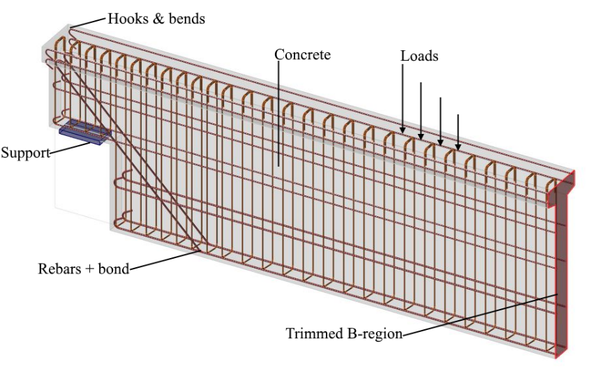
Las herramientas de diseño de armadura consideran modelos constitutivos más simplificados que los modelos utilizados para la verificación final de la estructura. Por lo tanto, la definición de la armadura en este paso debe considerarse un prediseño que deberá confirmarse/refinarse durante el paso de verificación final. El uso de las diferentes herramientas de diseño de armadura se ilustrará con el modelo mostrado en la Fig. 3, que consiste en un extremo de una viga simplemente apoyada de canto variable sometida a una carga uniformemente distribuida.
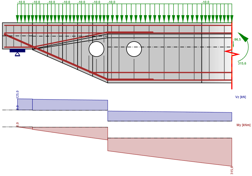
\[ \textsf{\textit{\footnotesize{Fig. 3\qquad Model used to illustrate the use of the reinforcement design tools.}}}\]
Análisis lineal
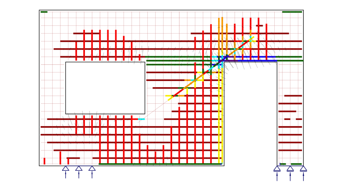
El análisis lineal considera propiedades de material elástico lineal y desprecia la armadura en la región de hormigón. Es, por tanto, un cálculo muy rápido que proporciona una primera visión de las zonas de tracción y compresión. Un ejemplo de dicho cálculo se muestra en la Fig. 4.
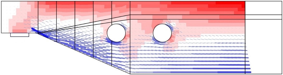
\[ \textsf{\textit{\footnotesize{Fig. 4\qquad Results from the linear analysis tool for defining reinforcement layout}}}\]
\[ \textsf{\textit{\footnotesize{(red: areas in compression, blue: areas in tension).}}}\]
Optimización topológica
La optimización topológica es un método que tiene como objetivo encontrar la distribución óptima de material en un volumen dado para una determinada configuración de cargas. La optimización topológica implementada en Idea StatiCa Detail utiliza un modelo de elementos finitos lineal. Cada elemento finito puede tener una densidad relativa del 0 al 100 %, que representa la cantidad relativa de material utilizado. Estas densidades de elemento son los parámetros de optimización del problema. La distribución de material resultante se considera óptima para el conjunto de cargas dado si minimiza la energía de deformación total del sistema. Por definición, la distribución óptima es también la geometría que tiene la mayor rigidez posible para las cargas dadas.
El proceso de optimización iterativo comienza con una distribución de densidad homogénea. El cálculo se realiza para múltiples fracciones de volumen total (20 %, 40 %, 60 % y 80 %), lo que permite al usuario seleccionar el resultado más práctico. La forma resultante consiste en celosías con bielas y tirantes y representa la forma óptima para los casos de carga dados (Fig. 5).
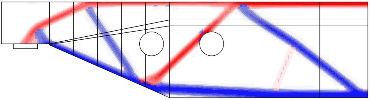
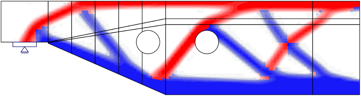
\[ \textsf{\textit{\footnotesize{Fig. 5\qquad Results from the topology optimization design tool with 20\% and 40\% effective volume}}}\]
\[ \textsf{\textit{\footnotesize{(red: areas in compression, blue: areas in tension).}}}\]
2 Modelo de análisis de IDEA StatiCa Detail
2.1 Introducción a la implementación del Método de los Elementos Finitos
El CSFM considera campos de tensiones continuos en el hormigón (elementos finitos 2D), complementados por elementos discretos de "barra" que representan la armadura (elementos finitos 1D). Por lo tanto, la armadura no está difusamente embebida en los elementos finitos 2D de hormigón, sino que se modela explícitamente y se conecta a ellos. En el modelo de cálculo se considera un estado plano de tensiones.
\[ \textsf{\textit{\footnotesize{Fig. 6\qquad Visualization of the calculation model of a structural element (trimmed beam) in Idea StatiCa Detail.}}}\]
Se pueden modelar tanto muros y vigas completas como detalles (partes) de vigas (región de discontinuidad aislada, también denominada extremo recortado). En el caso de muros y vigas completas, los apoyos deben definirse de manera que resulte una estructura (externamente) isostática (estáticamente determinada) o hiperestática (estáticamente indeterminada). La transferencia de carga en los extremos recortados de las vigas se introduce mediante una zona especial de transferencia de Saint-Venant, que garantiza una distribución realista de tensiones en la región del detalle analizado.
2.2 Soportes y componentes de transmisión de carga
Para modelar la mayoría de las situaciones durante el proceso de construcción, en el CSFM se dispone de numerosos tipos de soportes (Fig. 7) y componentes utilizados para la transmisión de cargas (Fig. 8).
Soportes
El soporte puntual puede modelarse de varias formas para garantizar que las tensiones no se concentren en un único punto, sino que se distribuyan sobre un área mayor. La primera opción es un soporte puntual distribuido (Fig. 7a), que distribuye uniformemente la carga en el borde del elemento a lo largo del ancho especificado.
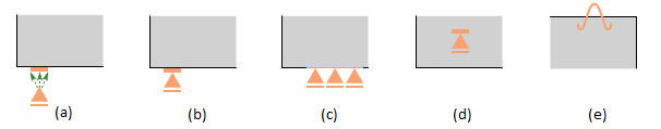
\[ \textsf{\textit{\footnotesize{Fig. 7\qquad Various types of supports:}}}\]
\[ \textsf{\textit{\footnotesize{(a) point distributed; (b) bearing plate; (c) line support; (d) patch support; (e) hanging.}}}\]
El soporte de parche (Fig. 7d), por otro lado, solo puede colocarse en el interior de un volumen de hormigón con un radio efectivo definido. Se conecta mediante elementos rígidos a los nodos de la malla de armadura dentro de dicho radio. Por tanto, es necesario definir una jaula de armadura alrededor del soporte de parche.
Para el modelado más preciso de algunos escenarios reales, existen otras dos opciones de soporte puntual. En primer lugar, el soporte puntual con una placa de apoyo de anchura y espesor definidos (Fig. 7b). El material de la placa de apoyo puede especificarse y toda la placa de apoyo se malla de forma independiente. En segundo lugar, existe un soporte colgante (Fig. 7e), que puede utilizarse para modelar anclajes de elevación o pernos de elevación.
El soporte lineal (Fig. 7c) puede definirse en un borde (especificando su longitud) o en el interior de un elemento (mediante una polilínea). También es posible especificar su rigidez y/o comportamiento no lineal (soporte a compresión/tracción o solo a compresión).
- Consulte las descripciones detalladas en Tipos de soportes en IDEA StatiCa Detail
Componentes de transmisión de carga
La introducción de cargas en la estructura también puede modelarse de varias formas. Para cargas puntuales, puede utilizarse una placa de apoyo (Fig. 8a) de manera similar al soporte puntual, distribuyendo la carga concentrada sobre un área mayor gracias a una placa de acero con anchura y espesor definidos.
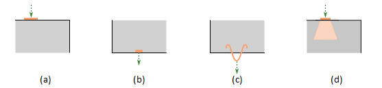
\[ \textsf{\textit{\footnotesize{Fig. 8\qquad Various types of load transfer components:}}}\]
\[ \textsf{\textit{\footnotesize{(a) bearing plate; (b) patch load; (c) hanging; (d) partially loaded area.}}}\]
La carga puntual puede aplicarse directamente sobre la superficie de la estructura con un radio de acción definido (la carga se aplica a los elementos de hormigón) o mediante un dispositivo transmisor especial denominado carga de parche (Fig. 8b y Fig. 9). La carga de parche permite transmitir la carga directamente a la armadura definida situada dentro del área del radio efectivo. Para garantizar el correcto funcionamiento de la carga de parche, es necesario definir un grupo de barras que se interconectarán con la carga (en las propiedades de la armadura). Cuando no se define la armadura interconectada, el mecanismo de transmisión de carga es el mismo que para la carga puntual colocada sobre la superficie del elemento, y la carga se transfiere mediante las restricciones a los elementos de hormigón, no directamente a la armadura.
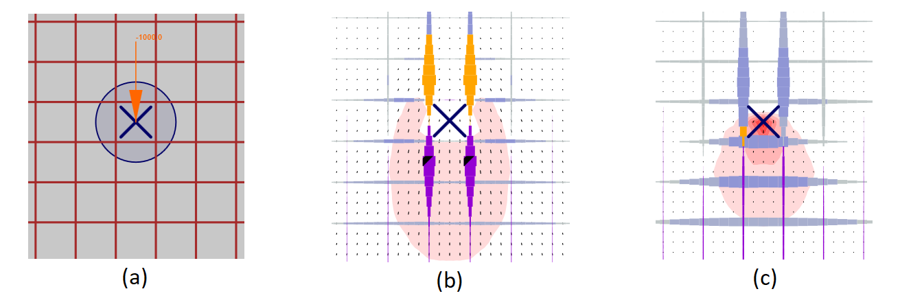
\[ \textsf{\textit{\footnotesize{Fig. 9\qquad Patch load: (a) load application; (b) load transferred through rebars (a group of bars for the load transfer is defined);}}}\]
\[ \textsf{\textit{\footnotesize{(c) load transferred through concrete (a group of bars for the load transfer is not defined).}}}\]
Los anclajes de elevación o pernos de elevación pueden modelarse mediante una carga colgante (Fig. 8c). El usuario puede emplear un área parcialmente cargada (Fig. 8d), que permite aumentar la capacidad resistente del hormigón a compresión según el Eurocódigo (no es posible utilizar este tipo de componente de transmisión de carga cuando se selecciona ACI). La estructura también puede cargarse con cargas lineales en los bordes, mediante una polilínea general o mediante cargas superficiales. La aplicación Detail es capaz de considerar automáticamente el peso propio en el análisis.
2.3 Transferencia de carga en los extremos rebajados de vigas
En muchos casos, es necesario modelar únicamente un detalle (parte) de un elemento estructural, como el apoyo de una viga, una abertura en el centro de la viga, etc. Este enfoque puede dar lugar a configuraciones de apoyo que son inestables pero admisibles en IDEA StatiCa Detail (incluido el caso de ausencia de apoyos). Sin embargo, en tales casos, también es necesario modelar la sección que representa la unión con la región B adyacente, incluyendo los esfuerzos internos en dicha sección que satisfagan el equilibrio. En ciertos casos (por ejemplo, al modelar el apoyo de una viga), el programa puede determinar automáticamente estos esfuerzos internos.
Entre la región B y la región de discontinuidad analizada, se crea automáticamente una zona de transferencia de Saint-Venant para garantizar una distribución realista de tensiones en la región analizada. El ancho de la zona de transferencia se determina como la mitad del canto de la sección. Dado que el único propósito de la zona de Saint-Venant es lograr una distribución adecuada de tensiones en el resto del modelo, no se muestran resultados de esta zona en la verificación y no se consideran criterios de parada en ella.
El borde de la zona de Saint-Venant que representa el extremo rebajado de la viga se modela como rígido, es decir, puede girar pero debe permanecer plano. Esto se consigue conectando todos los nodos del MEF del borde a un nodo independiente situado en el centro de inercia de la sección mediante un elemento de cuerpo rígido (RBE2). Los esfuerzos internos del elemento pueden entonces aplicarse en este nodo, como se muestra en la Fig. 10.
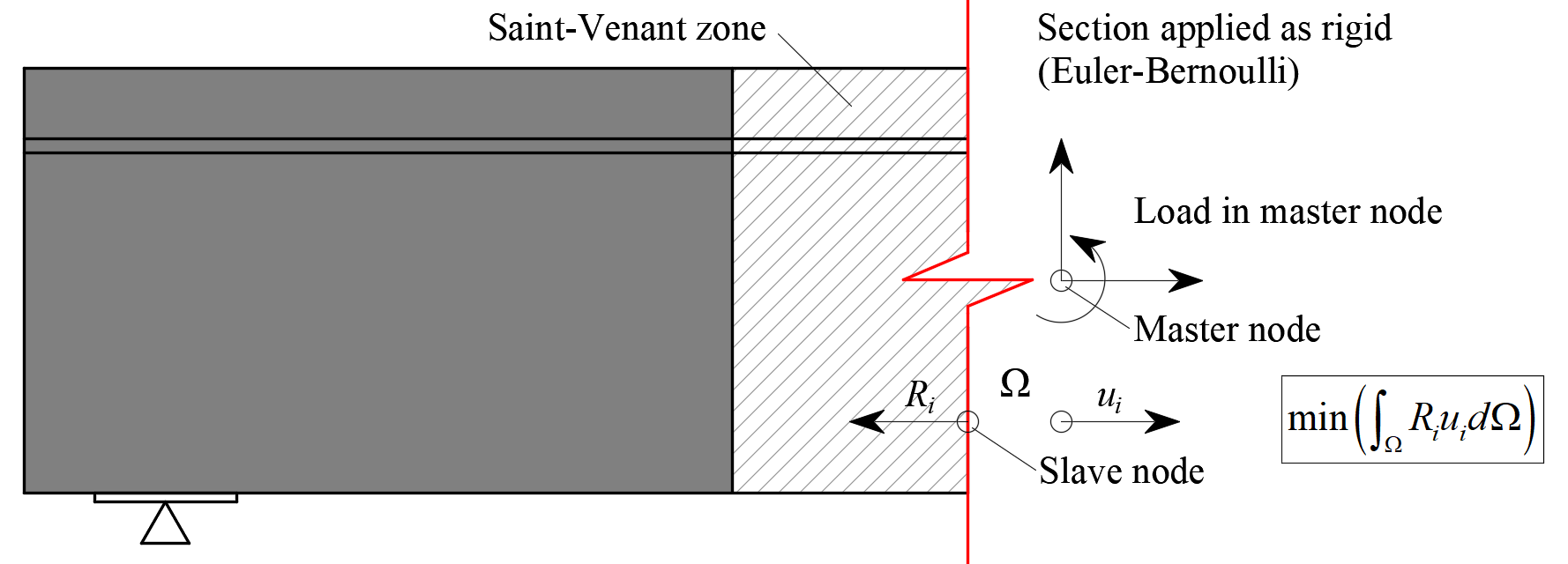
\[ \textsf{\textit{\footnotesize{Fig. 10\qquad Transfer of internal forces at a trimmed end.}}}\]
2.4 Modificación geométrica de secciones transversales
La reducción de la sección transversal se realiza automáticamente para estructuras definidas como viga o nudo de pórtico (definidas por el eje x y una sección transversal). Esta modificación se aplica automáticamente en secciones transversales con alas muy anchas (Fig. 11) y se basa en la hipótesis de que un campo de tensiones de compresión se expande desde el alma con un ángulo de 45°, de modo que el ancho reducido mencionado sería el ancho máximo capaz de transmitir cargas.
Nótese que el método para determinar el ancho eficaz del ala implementado en CSFM es diferente del indicado en 5.3.2.1 EN 1992-1-1 (2015) o en 9.2.4.4 ACI 318-19. Además de la geometría, el ancho eficaz del ala según el Eurocódigo se ve afectado explícitamente por las longitudes de vano y las condiciones de contorno de la estructura.
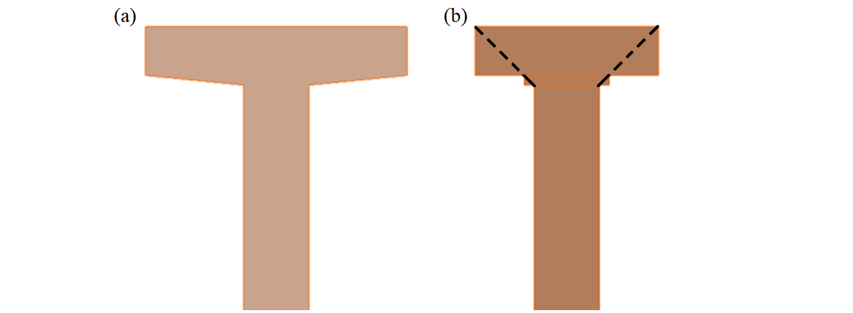
\[ \textsf{\textit{\footnotesize{Fig. 11\qquad Width reduction of a cross-section: (a) user input; (b) FE model – automatically determined reduced flange width.}}}\]
En el caso de cartelas situadas en el plano horizontal (Fig. 12), cada cartela se divide en cinco secciones a lo largo de su longitud. Cada una de estas secciones se modela como un muro de espesor constante, igual al espesor real en el punto medio de la sección correspondiente.
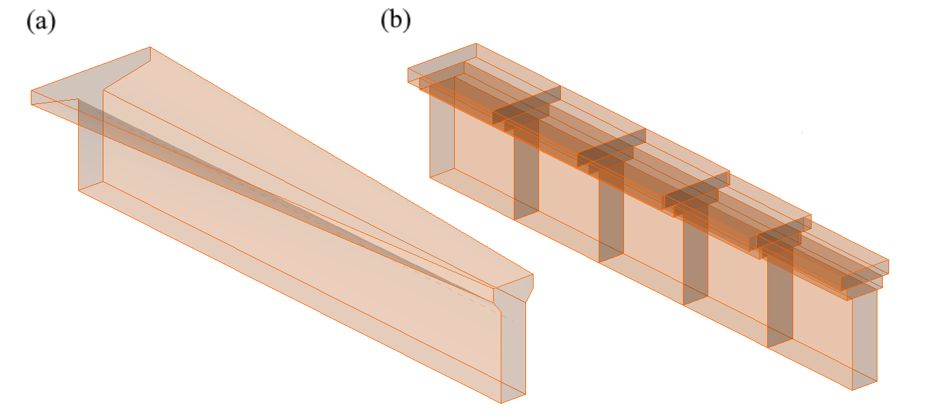
\[ \textsf{\textit{\footnotesize{Fig. 12\qquad Horizontal haunch: (a) user input; (b) FE model – a haunch automatically divided into five sections.}}}\]
2.5 Tipos de elementos del Método de los Elementos Finitos
El modelo de análisis por elementos finitos no lineal (inelástico) se crea mediante varios tipos de elementos finitos utilizados para modelar el hormigón, la armadura y la adherencia entre ellos. Los elementos de hormigón y de armadura se mallan de forma independiente y luego se conectan entre sí mediante restricciones multipunto (elementos MPC). Esto permite que la armadura ocupe una posición relativa arbitraria respecto al hormigón. Si se va a calcular la verificación de la longitud de anclaje, se insertan elementos muelle de adherencia y de extremo de anclaje entre la armadura y los elementos MPC.
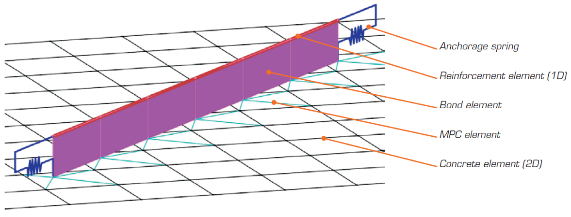
\[ \textsf{\textit{\footnotesize{Fig. 13\qquad Finite element model: reinforcement elements mapped to concrete mesh using MPC elements and bond elements.}}}\]
Hormigón
El hormigón se modela mediante elementos lámina cuadriláteros y triláteros, CQUAD4 y CTRIA3. Estos pueden definirse por cuatro o tres nodos, respectivamente. En estos elementos se asume únicamente estado plano de tensiones, es decir, no se consideran las tensiones ni las deformaciones en la dirección z.
Cada elemento tiene cuatro o tres puntos de integración situados aproximadamente a 1/4 de su tamaño. En cada punto de integración de cada elemento se calculan las direcciones de las deformaciones principales α1, α2. En ambas direcciones, las tensiones principales σc1, σc2 y las rigideces E1, E2 se evalúan según el diagrama tensión-deformación del hormigón especificado, conforme a la Fig. 2. Cabe señalar que el efecto del ablandamiento a compresión acopla el comportamiento de la dirección principal de compresión con el estado real de la otra dirección principal.
Armadura
Las barras se modelan mediante elementos 1D de dos nodos tipo "barra" (CROD), que solo tienen rigidez axial. Estos elementos se conectan a elementos especiales de "adherencia" desarrollados para modelar el comportamiento de deslizamiento entre una barra de armadura y el hormigón circundante. Estos elementos de adherencia se conectan posteriormente mediante elementos MPC (restricción multipunto) a la malla que representa el hormigón. Este enfoque permite el mallado independiente de la armadura y el hormigón, garantizando su interconexión en una etapa posterior.
Elementos de adherencia
La longitud de anclaje se verifica implementando las tensiones tangenciales de adherencia entre los elementos de hormigón (2D) y los elementos de barra de armadura (1D) en el modelo de elementos finitos. Con este fin, se desarrolló un tipo de elemento finito de "adherencia".
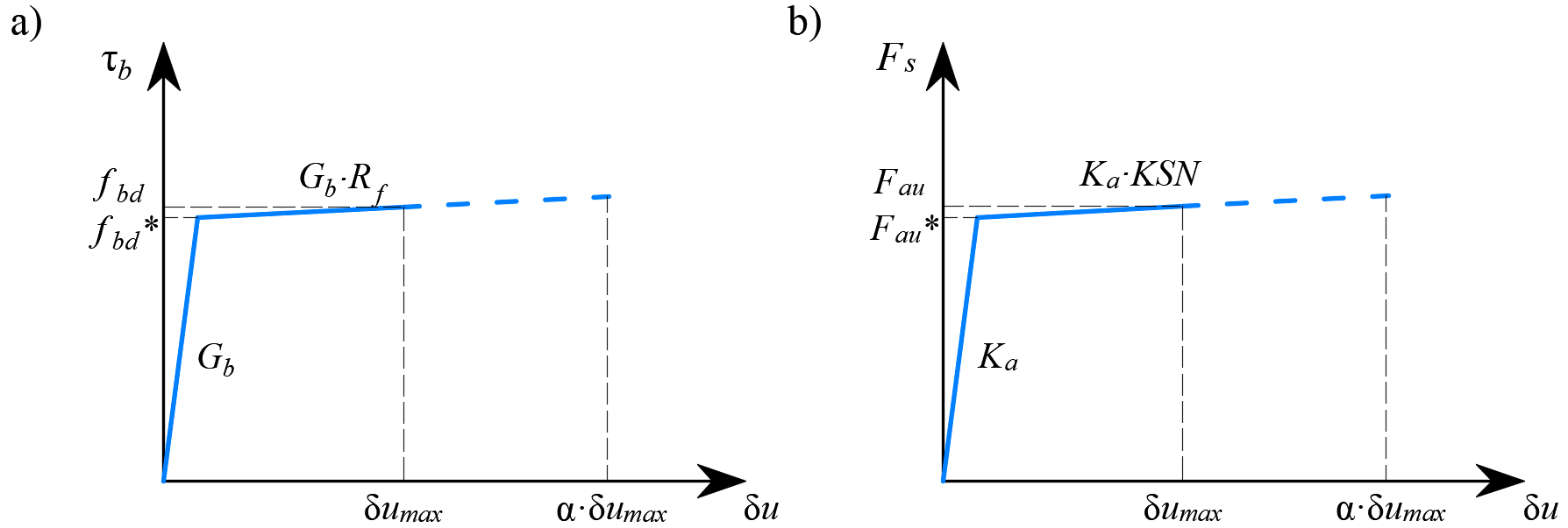
La definición del elemento de adherencia es similar a la de un elemento lámina (CQUAD4). También se define por 4 nodos, pero a diferencia de una lámina, solo tiene rigidez no nula a cortante entre los dos nodos superiores y los dos nodos inferiores. En el modelo, los nodos superiores se conectan a los elementos que representan la armadura y los nodos inferiores a los que representan el hormigón. El comportamiento de este elemento se describe mediante la tensión de adherencia, τb, como función bilineal del deslizamiento entre los nodos superiores e inferiores, δu, véase la Fig. 14.
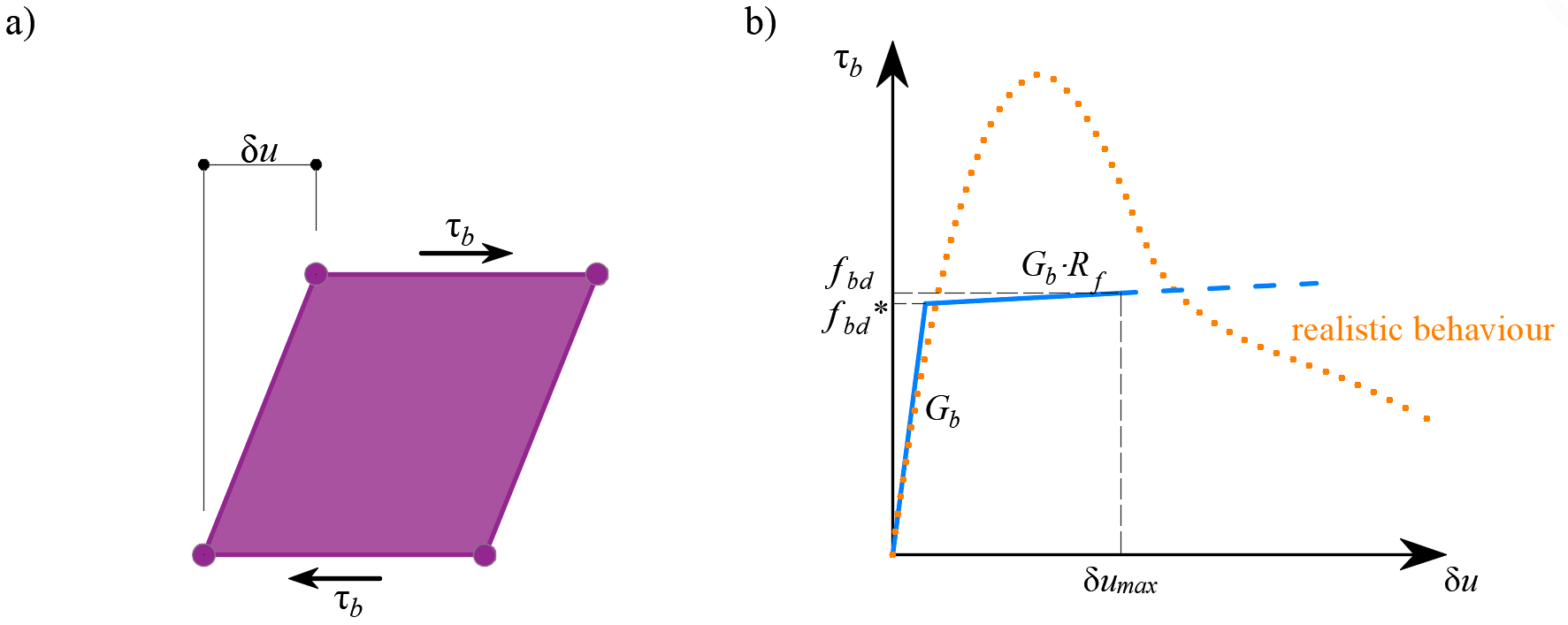
\[ \textsf{\textit{\footnotesize{Fig. 14\qquad (a) conceptual illustration of the deformation of a bond element; (b) a stress-deformation function.}}}\]
El módulo de rigidez elástica de la relación adherencia-deslizamiento, Gb, se define como sigue:
\[G_b = k_g \cdot \frac{E_c}{Ø}\]
donde:
kg coeficiente que depende de la superficie de la barra de armadura (por defecto kg = 0,2)
Ec módulo de elasticidad del hormigón (tomado como Ecm en el caso de EN)
Ø el diámetro de la barra de armadura
Los valores de cálculo (valores mayorados) de la tensión tangencial de adherencia última, fbd, proporcionados en los códigos de diseño seleccionados EN 1992-1-1 o ACI 318-19, se utilizan para verificar la longitud de anclaje. El endurecimiento de la rama plástica se calcula por defecto como Gb/105.
Muelle de anclaje
La disposición de extremos de anclaje en las barras de armadura (es decir, dobleces, ganchos, lazos…), que cumple con las prescripciones de los códigos de diseño, permite reducir la longitud de anclaje básica de las barras (lb,net) por un cierto factor β (denominado a continuación "coeficiente de anclaje"). El valor de cálculo de la longitud de anclaje (lb) se calcula entonces como sigue:
\[l_b = \left(1 - \beta\right)l_{b,net}\]
La reducción prevista en lb,net es equivalente a la activación de la barra de armadura en su extremo a un porcentaje de su capacidad máxima dado por el coeficiente de reducción del anclaje, como se muestra en la Fig. 15a.

\[ \textsf{\textit{\footnotesize{Fig. 15\qquad Model for the reduction of the anchorage length:}}}\]
\[ \textsf{\textit{\footnotesize{(a) anchorage force along the anchorage length of the reinforcing bar; (b) slip-anchorage force constitutive relationship.}}}\]
La reducción de la longitud de anclaje se incluye en el modelo de elementos finitos mediante un elemento muelle en el extremo de la barra (Fig. 15), definido por el modelo constitutivo mostrado en la Fig. 15b. La fuerza máxima transmitida por este muelle (Fau) es:
\[F_{au} = \beta \cdot A_s \cdot f_{yd}\]
donde :
β el coeficiente de anclaje basado en el tipo de anclaje,
As la sección transversal de la barra de armadura,
fyd el valor de cálculo (valor mayorado) de la resistencia de fluencia de la armadura.
2.6 Mallado
Los elementos finitos se implementan internamente y el modelo de análisis se genera automáticamente sin necesidad de una interacción experta por parte del usuario. Una parte importante de este proceso es el mallado.
Hormigón
Todos los elementos de hormigón se mallan conjuntamente. El tamaño de elemento recomendado se calcula automáticamente por la aplicación en función del tamaño y la forma de la estructura, teniendo en cuenta el diámetro de la barra de armadura más grande. Además, el tamaño de elemento recomendado garantiza que se generen un mínimo de 4 elementos en las partes más delgadas de la estructura, como columnas esbeltas o losas delgadas, para asegurar resultados fiables en estas zonas. El número máximo de elementos de hormigón está limitado a 5000, pero este valor es suficiente para proporcionar el tamaño de elemento recomendado para la mayoría de las estructuras. Los proyectistas pueden seleccionar siempre un tamaño de elemento de hormigón definido por el usuario modificando el multiplicador del tamaño de malla predeterminado.
Armadura
La armadura se divide en elementos con una longitud aproximadamente igual al tamaño del elemento de hormigón. Una vez generadas las mallas de armadura y hormigón, se interconectan mediante elementos de adherencia, como se muestra en la Fig. 13.
Placas de apoyo
Las partes estructurales auxiliares, como las placas de apoyo, se mallan de forma independiente. El tamaño de estos elementos se calcula como 2/3 del tamaño de los elementos de hormigón en la zona de unión. Los nodos de la malla de la placa de apoyo se conectan a continuación a los nodos del borde de la malla de hormigón mediante elementos de restricción por interpolación (RBE3).
Cargas y apoyos
Las cargas en área y los apoyos en área se conectan únicamente a la armadura, como se muestra en la Fig. 16. Por tanto, es necesario definir la armadura alrededor de ellos. La conexión a todos los nodos de la armadura dentro del radio efectivo se garantiza mediante elementos RBE3 con peso igual.
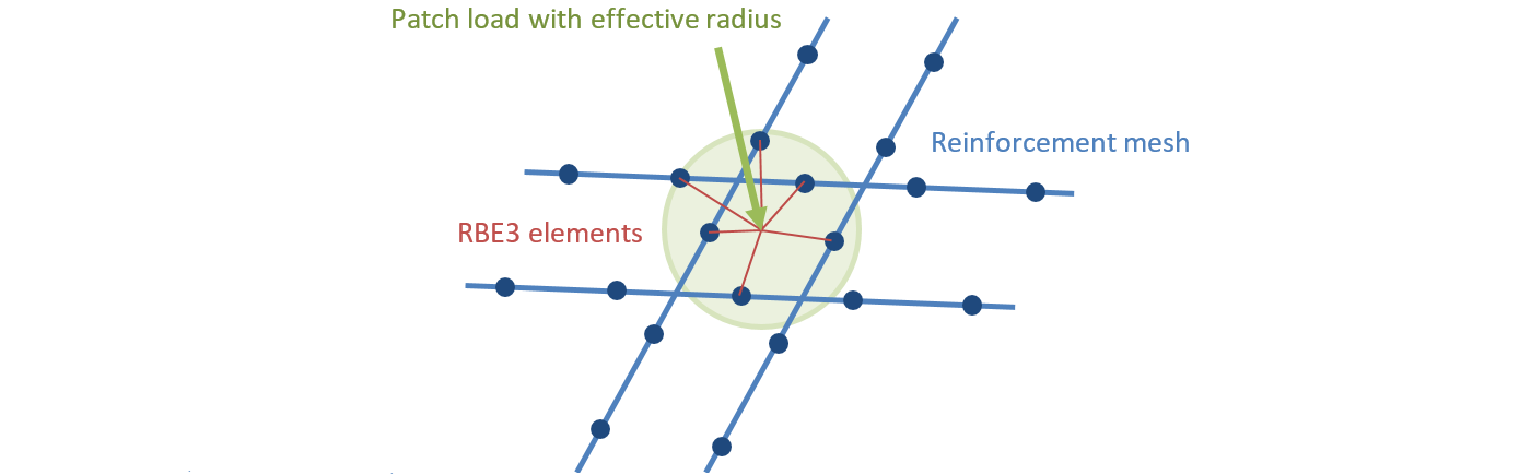
\[ \textsf{\textit{\footnotesize{Fig. 16\qquad Patch load mapping to reinforcement mesh.}}}\]
Los apoyos lineales y las cargas lineales se conectan a los nodos de la malla de hormigón mediante elementos RBE3 en función del ancho especificado o del radio efectivo. El peso de las conexiones es inversamente proporcional a la distancia al apoyo o al impulso de carga.
- Más información sobre la interconexión entre las cargas individuales y la malla en Descripción general de los impulsos de carga en la aplicación Detail
2.7 Método de solución y algoritmo de control de carga
Se utiliza un algoritmo estándar de Newton-Raphson (NR) completo para encontrar la solución a un problema de MEF no lineal.
En general, el algoritmo NR no converge con frecuencia cuando la carga total se aplica en un único paso. Un enfoque habitual, que también se utiliza aquí, consiste en aplicar la carga de forma secuencial en múltiples incrementos y utilizar el resultado del incremento de carga anterior para iniciar la solución de Newton del siguiente. Con este fin, se implementó un algoritmo de control de carga sobre el Newton-Raphson. En el caso de que las iteraciones NR no converjan, el incremento de carga actual se reduce a la mitad de su valor y se reintenta el proceso de iteraciones NR.
Un segundo propósito del algoritmo de control de carga es encontrar la carga crítica, que corresponde a ciertos "criterios de parada": concretamente, la deformación máxima en el hormigón, el deslizamiento máximo en los elementos de adherencia, el desplazamiento máximo en los elementos de anclaje y la deformación máxima en las barras de armadura. La carga crítica se determina mediante el método de bisección. En el caso de que el criterio de parada se supere en cualquier punto del modelo, los resultados del último incremento de carga se descartan y se calcula un nuevo incremento de la mitad del tamaño del anterior. Este proceso se repite hasta que la carga crítica se encuentra con una determinada tolerancia de error.
Para el hormigón, el criterio de parada se estableció en una deformación del 5% en compresión (es decir, aproximadamente un orden de magnitud mayor que la deformación de rotura real del hormigón) y del 7% en tracción en los puntos de integración de los elementos de lámina. En tracción, el valor se estableció para permitir que se alcance primero la deformación límite en la armadura, que suele ser de aproximadamente el 5% sin tener en cuenta la rigidización a tracción. En compresión, el valor se eligió entre varias alternativas como aquel que es suficientemente grande para que los efectos del aplastamiento sean visibles en los resultados, pero suficientemente pequeño para no causar demasiados problemas de estabilidad numérica.
\[ \textsf{\textit{\footnotesize{Fig. 17\qquad Constitutive relationship of bond and anchorage elements used for anchorage length verification:}}}\]
\[ \textsf{\textit{\footnotesize{(a) bond shear stress slip response of a bond element; (b) force-displacement response of an anchorage element.}}}\]
Para la armadura, el criterio de parada se define en términos de tensiones. Dado que se modelan las tensiones en la fisura, el criterio en tracción corresponde a la resistencia a tracción de la armadura teniendo en cuenta el coeficiente de seguridad. El mismo valor se utiliza para el criterio en compresión.
El criterio de parada en los elementos de adherencia y los muelles de anclaje es α·δumax, donde δumax es el deslizamiento máximo utilizado en las verificaciones normativas y α = 10.
2.8 Presentación de resultados
Los resultados se presentan de forma independiente para el hormigón y para los elementos de armadura. Los valores de tensión y deformación en el hormigón se calculan en los puntos de integración de los elementos de lámina. Sin embargo, dado que no es práctico presentar los datos de esta manera, los resultados se presentan por defecto en los nodos, como el valor máximo de tensión de compresión de los puntos de integración de Gauss adyacentes en los elementos conectados (Fig. 18). Cabe señalar que esta representación puede subestimar localmente los resultados en los bordes comprimidos de los elementos en el caso de que el tamaño del elemento finito sea similar al canto de la zona de compresión.
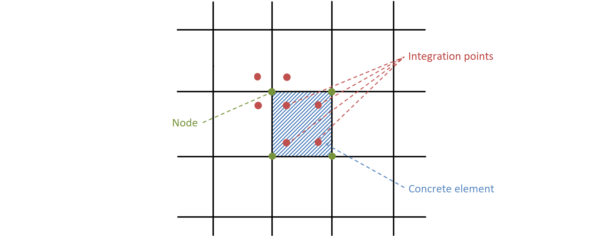
Fig. 18 - Elemento finito de hormigón con puntos de integración y nodos: presentación de los resultados para el hormigón en nodos y en elementos finitos.
Los resultados para los elementos finitos de armadura son constantes para cada elemento (un valor, por ejemplo, para las tensiones en el acero) o lineales (dos valores, para los resultados de adherencia). Para los elementos auxiliares, como los elementos de placas de apoyo, solo se presentan las deformaciones.
3 Verificación del modelo
3.1 Estados límite y cálculo de la anchura de fisura
La evaluación de la estructura mediante el CSFM se realiza mediante dos análisis diferentes: uno para las combinaciones de carga en estado límite de servicio y otro para las de estado límite último. El análisis de servicio asume que el comportamiento último del elemento es satisfactorio y que las condiciones de plastificación del material no se alcanzarán en los niveles de carga de servicio. Este enfoque permite el uso de modelos constitutivos simplificados (con una rama lineal del diagrama tensión-deformación del hormigón) para el análisis de servicio, con el fin de mejorar la estabilidad numérica y la velocidad de cálculo. Por ello, se recomienda utilizar el flujo de trabajo que se presenta a continuación, en el que el análisis en estado límite último se realiza como primer paso.
Análisis en estado límite último
Las diferentes verificaciones requeridas por los códigos de diseño específicos se evalúan a partir de los resultados directos proporcionados por el modelo. Las verificaciones en ELU se llevan a cabo para la resistencia del hormigón, la resistencia de la armadura y el anclaje (tensiones tangenciales de adherencia).
Para garantizar un diseño eficiente del elemento estructural, se recomienda encarecidamente realizar un análisis preliminar que tenga en cuenta los siguientes pasos:
- Seleccionar las combinaciones de carga más críticas.
- Calcular únicamente las combinaciones de carga en Estado Límite Último (ELU).
- Utilizar una malla gruesa (aumentando el multiplicador del tamaño de malla predeterminado en Configuración (Fig. 19)).
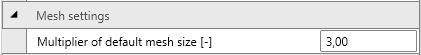
\[ \textsf{\textit{\footnotesize{Fig. 19\qquad Mesh multiplier.}}}\]
Este modelo calculará muy rápidamente, lo que permitirá a los proyectistas revisar el detallado del elemento estructural de forma eficiente y repetir el análisis hasta que se cumplan todos los requisitos de verificación para las combinaciones de carga más críticas. Una vez cumplidos todos los requisitos de verificación de este análisis preliminar, se sugiere incluir las combinaciones de carga última completas y utilizar un tamaño de malla fino (el tamaño de malla recomendado por el programa). El usuario puede cambiar el tamaño de malla mediante el multiplicador, que puede tomar valores de 0,5 a 5 (Fig. 19).
Los resultados y verificaciones básicos (tensión, deformación y utilización (es decir, el valor calculado/valor límite del código), así como la dirección de las tensiones principales en el caso de elementos de hormigón) se muestran mediante diferentes representaciones gráficas en las que la compresión se presenta generalmente en rojo y la tracción en azul. Se pueden resaltar los valores mínimos y máximos globales de toda la estructura, así como los valores mínimos y máximos de cada parte definida por el usuario. En una pestaña separada del programa se pueden mostrar resultados avanzados como valores tensoriales, deformaciones de la estructura y cuantías de armadura (efectiva y geométrica) utilizadas para calcular la rigidización a tracción de las barras de armadura. Además, se pueden presentar las cargas y reacciones para las combinaciones o casos de carga seleccionados.
Análisis en estado límite de servicio
Las verificaciones en ELS se realizan para la limitación de tensiones, la anchura de fisura y los límites de deformación. Las tensiones se comprueban en los elementos de hormigón y de armadura según el código aplicable, de manera similar a la especificada para el ELU.
El análisis de servicio contiene ciertas simplificaciones de los modelos constitutivos que se utilizan para el análisis en estado límite último. Se asume una adherencia perfecta, es decir, la longitud de anclaje no se verifica en servicio. Además, se desprecia la rama plástica de la curva tensión-deformación del hormigón en compresión, mientras que la rama elástica es lineal e ilimitada. Estas simplificaciones mejoran la estabilidad numérica y la velocidad de cálculo, y no reducen la generalidad de la solución siempre que los límites de tensión del material resultantes en servicio estén claramente por debajo de sus puntos de plastificación (como exigen las normas). Por tanto, los modelos simplificados utilizados para el servicio solo son válidos si se cumplen todos los requisitos de verificación.
Cálculo del ancho de fisura y rigidización a tracción
Cálculo del ancho de fisura
Hay dos formas de calcular los anchos de fisura: fisuración estabilizada y no estabilizada. Según la cuantía geométrica de armadura en cada parte de la estructura se decide qué tipo de modelo de cálculo de fisuras se utilizará (TCM para fisuración estabilizada y POM para el modelo de fisuración no estabilizada).
\( \textsf{\textit{\footnotesize{Fig. 20 \qquad Crack width calculation: (a) considered crack kinematics; (b) projection of crack kinematics into the principal}}}\) \( \textsf{\textit{\footnotesize{directions of the reinforcing bar; (c) crack width in the direction of the reinforcing bar for stabilized cracking; (d) cases with}}}\) \( \textsf{\textit{\footnotesize{local non-stabilized cracking regardless of the reinforcement amount; (e) crack width in the direction of the reinforcing bar}}}\)\( \textsf{\textit{\footnotesize{for non-stabilized cracking.}}}\)
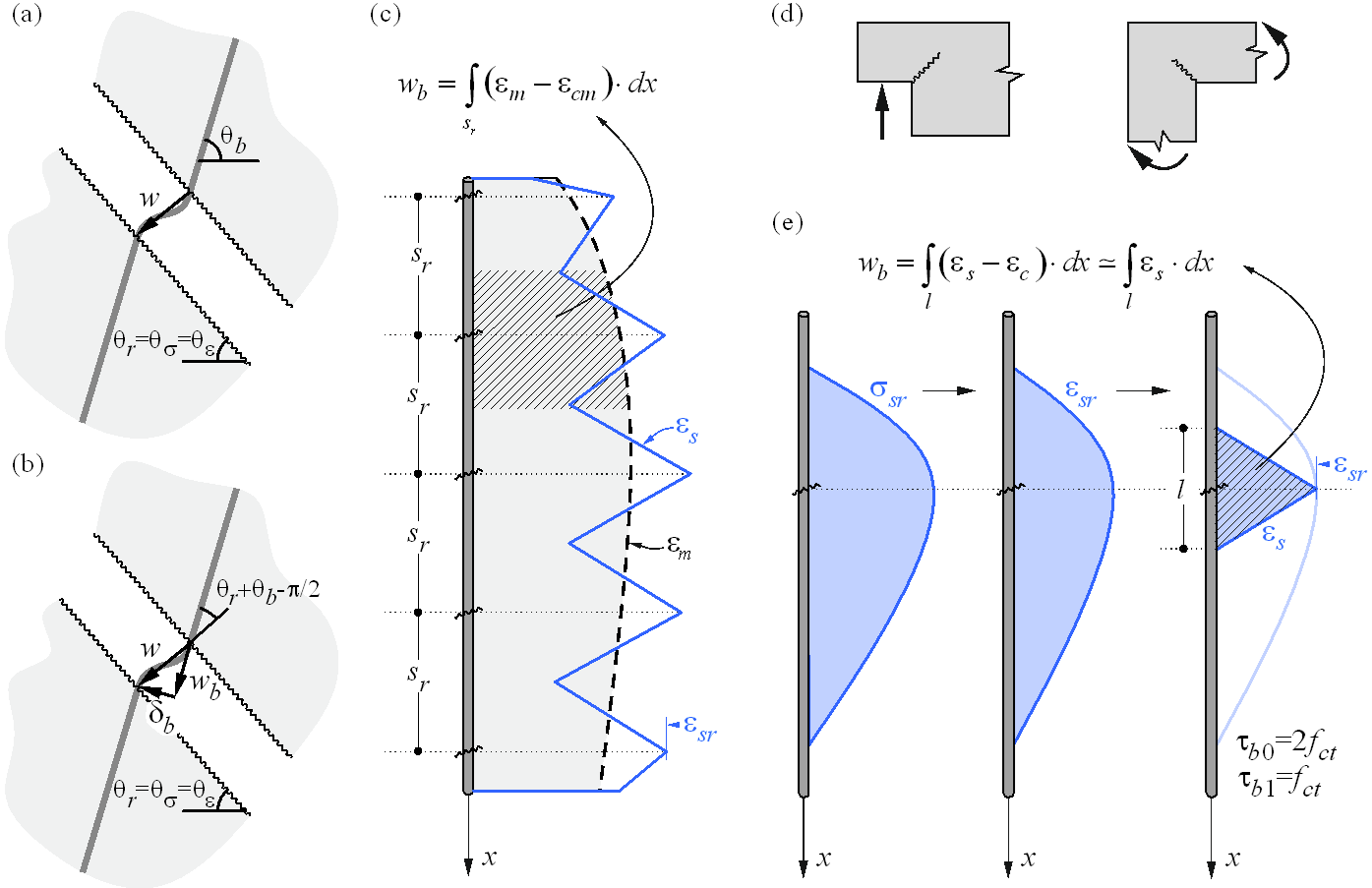
Mientras que el CSFM proporciona un resultado directo para la mayoría de las verificaciones (p. ej., capacidad del elemento, flechas…), los resultados del ancho de fisura se calculan a partir de los resultados de deformación de la armadura proporcionados directamente por el análisis de elementos finitos siguiendo la metodología descrita en la Fig. 20. Se considera una cinemática de fisura sin deslizamiento (apertura pura de fisura) (Fig. 20a), lo cual es coherente con las hipótesis principales del modelo. Las direcciones principales de tensiones y deformaciones definen la inclinación de las fisuras (θr = θs= θe). Según la (Fig. 20b), el ancho de fisura (w) puede proyectarse en la dirección de la barra de armadura (wb), dando lugar a:
\[w = \frac{w_b}{\cos\left(θ_r + θ_b - \frac{π}{2}\right)}\]
donde θb es la inclinación de la barra.
Tenga en cuenta que el programa muestra valores de θr y θb < π/2. Esto significa que la ecuación anterior es válida para los casos en que la armadura y la fisura atraviesan cuadrantes diferentes del sistema de coordenadas cartesiano, como se muestra en la Fig. 20, donde la armadura atraviesa los cuadrantes I y III y la fisura los cuadrantes II y IV. Para los casos en que la armadura y la fisura atraviesan los mismos cuadrantes, la ecuación debe modificarse de la siguiente manera:
\[w = \frac{w_b}{\cos\left(-θ_r + θ_b + \frac{π}{2}\right)}\]
La componente wb se calcula de forma coherente a partir de los modelos de rigidización a tracción integrando las deformaciones de la armadura. Para las regiones con patrones de fisuración completamente desarrollados, las deformaciones medias calculadas (em) a lo largo de las barras de armadura se integran directamente a lo largo de la separación entre fisuras (sr), como se indica en la (Fig. 20c). Aunque este enfoque para calcular las direcciones de las fisuras no corresponde a la posición real de las fisuras, proporciona valores representativos que conducen a resultados de ancho de fisura comparables con los valores de ancho de fisura requeridos por la normativa en la posición de la barra de armadura.
Se observan situaciones especiales en las esquinas cóncavas de la estructura calculada. En este caso, la esquina predefine la posición de una fisura única que se comporta de forma no estabilizada antes de que se desarrollen fisuras adyacentes adicionales. Estas fisuras adicionales generalmente se desarrollan después del rango de servicio (Mata-Falcón 2015), lo que justifica calcular los anchos de fisura en dicha región como si fueran no estabilizadas (Fig. 21).
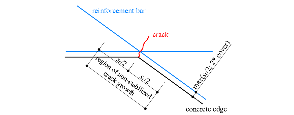
\[ \textsf{\textit{\footnotesize{Fig. 21\qquad Definition of the region at concave corners in which the crack width is computed as if it were non-stabilized.}}}\]
Rigidización a tracción
La implementación de la rigidización a tracción distingue entre casos de patrones de fisuración estabilizada y no estabilizada. En ambos casos, el hormigón se considera completamente fisurado antes de la carga por defecto.
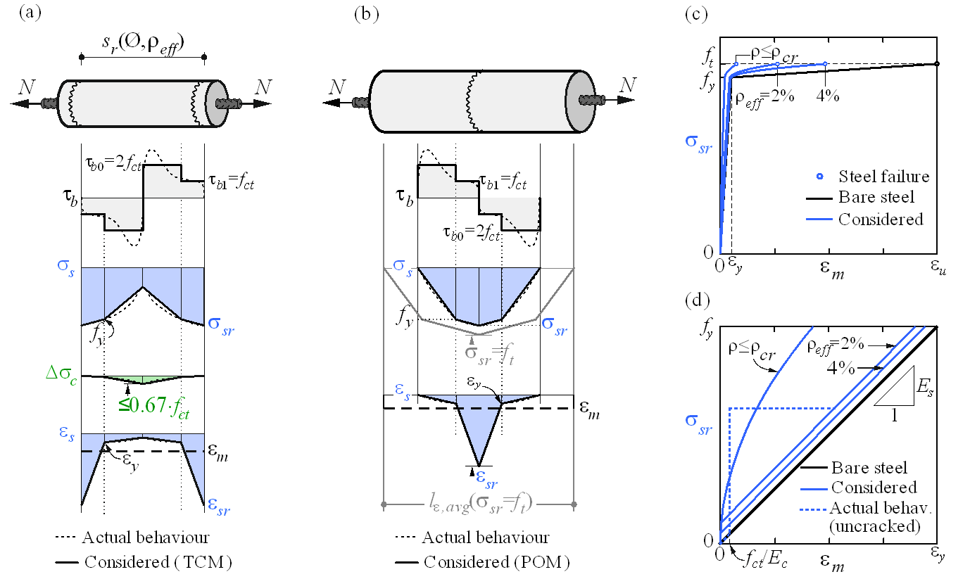
\( \textsf{\textit{\footnotesize{Fig. 22\qquad Tension stiffening model: (a) tension chord element for stabilized cracking with distribution of bond shear,}}}\) \( \textsf{\textit{\footnotesize{steel and concrete stresses, and steel strains between cracks, considering average crack spacing); (b) pull-out assumption}}}\) \( \textsf{\textit{\footnotesize{for non-stabilized cracking with distribution of bond shear and steel stresses and strains around the crack; (c) resulting}}}\) \( \textsf{\textit{\footnotesize{tension chord behavior in terms of reinforcement stresses at the cracks and average strains for European B500B steel;}}}\) \( \textsf{\textit{\footnotesize{(d) detail of the initial branches of the tension chord response.}}}\)
Fisuración estabilizada
En patrones de fisuración completamente desarrollados, la rigidización a tracción se introduce utilizando el Modelo de Cordón en Tracción (TCM) (Marti et al. 1998; Alvarez 1998) – Fig. 22a – que ha demostrado proporcionar excelentes predicciones de respuesta a pesar de su simplicidad (Burns 2012). El TCM asume una relación tensión tangencial de adherencia-deslizamiento escalonada, rígida y perfectamente plástica con τb = τb0 =2 fctm para σs ≤ fy y τb =τb1 = fctm para σs > fy. Tratando cada barra de armadura como un cordón en tracción – Fig. 22b y Fig. 22a – se puede determinar la distribución de la tensión tangencial de adherencia, las tensiones en el acero y en el hormigón y, por tanto, la distribución de deformaciones entre dos fisuras para cualquier valor dado de las tensiones máximas en el acero (o deformaciones) en las fisuras.
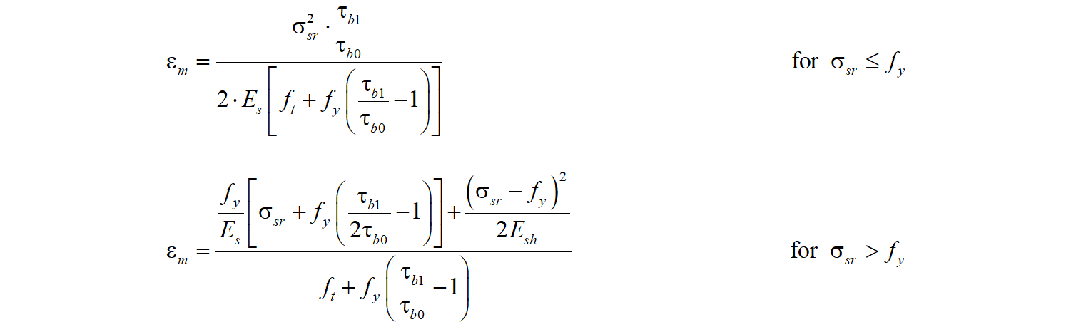
Para sr = sr0, puede o no formarse una nueva fisura porque en el centro entre dos fisuras σc1 = fct. En consecuencia, la separación entre fisuras puede variar en un factor de dos, es decir, sr = λsr0, con l = 0,5…1,0. Asumiendo un cierto valor para λ, la deformación media del cordón (εm) puede expresarse como función de las tensiones máximas en la armadura (es decir, tensiones en las fisuras, σsr). Para el diagrama tensión-deformación bilineal idealizado de las barras de armadura desnudas considerado por defecto en el CSFM, se obtienen las siguientes expresiones analíticas en forma cerrada (Marti et al. 1998):
\[\varepsilon_m = \frac{\sigma_{sr}}{E_s} - \frac{\tau_{b0}s_r}{E_s Ø}\]
\[\textrm{for}\qquad\qquad\sigma_{sr} \le f_y\]
\[{\varepsilon_m} = \frac{{{{\left( {{\sigma_{sr}} - {f_y}} \right)}^2}Ø}}{{4{E_{sh}}{\tau _{b1}}{s_r}}}\left( {1 - \frac{{{E_{sh}}{\tau_{b0}}}}{{{E_s}{\tau_{b1}}}}} \right) + \frac{{\left( {{\sigma_{sr}} - {f_y}} \right)}}{{{E_s}}}\frac{{{\tau_{b0}}}}{{{\tau_{b1}}}} + \left( {{\varepsilon_y} - \frac{{{\tau_{b0}}{s_r}}}{{{E_s}Ø}}} \right)\]
\[\textrm{for}\qquad\qquad{f_y} \le {\sigma _{sr}} \le \left( {{f_y} + \frac{{2{\tau _{b1}}{s_r}}}{Ø}} \right)\]
\[ \varepsilon_m = \frac{f_s}{E_s} + \frac{\sigma_{sr}-f_y}{E_{sh}} - \frac{\tau_{b1} s_r}{E_{sh} Ø}\]
\[\textrm{for}\qquad\qquad\left(f_y + \frac{2\tau_{b1}s_r}{Ø}\right) \le \sigma_{sr} \le f_t\]
donde:
Esh el módulo de endurecimiento del acero Esh = (ft – fy)/(εu – fy /Es) ,
Es módulo de elasticidad de la armadura,
Ø diámetro de la barra de armadura,
sr separación entre fisuras,
σsr tensiones de la armadura en las fisuras,
σs tensiones reales de la armadura,
fy límite elástico de la armadura.
La implementación del CSFM en IDEA StatiCa Detail considera la separación media entre fisuras por defecto al realizar el análisis del campo de tensiones asistido por ordenador. La separación media entre fisuras se considera igual a 2/3 de la separación máxima entre fisuras (λ = 0,67), lo que sigue las recomendaciones realizadas sobre la base de ensayos de flexión y tracción (Broms 1965; Beeby 1979; Meier 1983). Cabe señalar que los cálculos del ancho de fisura consideran una separación máxima entre fisuras (λ = 1,0) con el fin de obtener valores conservadores.
La aplicación del TCM depende de la cuantía de armadura y, por tanto, la asignación de un área de hormigón apropiada que trabaje a tracción entre las fisuras a cada barra de armadura es crucial. Se ha desarrollado un procedimiento numérico automático para definir la cuantía de armadura efectiva correspondiente (ρeff = As/Ac,eff) para cualquier configuración, incluida la armadura inclinada (Fig. 23).
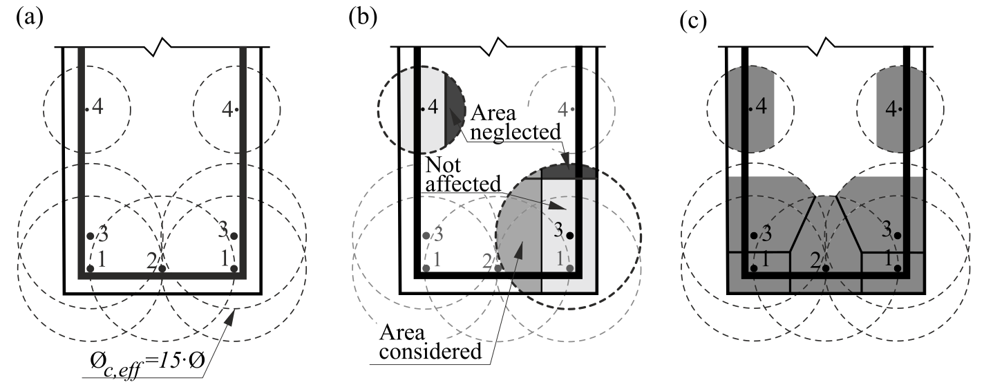
\( \textsf{\textit{\footnotesize{Fig. 23\qquad Effective area of concrete in tension for stabilized cracking: (a) maximum concrete area that can be activated;}}}\) \( \textsf{\textit{\footnotesize{(b) cover and global symmetry condition; (c) resultant effective area.}}}\)
Fisuración no estabilizada
Las fisuras existentes en regiones con cuantías geométricas de armadura inferiores a ρcr, es decir, la cuantía mínima de armadura para la cual la armadura es capaz de soportar la carga de fisuración sin plastificar, son generadas por acciones no mecánicas (p. ej., retracción) o por la propagación de fisuras controladas por otras armaduras. El valor de esta armadura mínima se obtiene de la siguiente manera:
\[{\rho _{cr}} = \frac{{{f_{ct}}}}{{{f_y} - \left( {n - 1} \right){f_{ct}}}}\]
donde:
fy límite elástico de la armadura,
fct resistencia a tracción del hormigón,
n relación modular, n = Es / Ec .
Para hormigón y acero de armadura convencionales, ρcr es aproximadamente del 0,6%.
Para estribos con cuantías de armadura inferiores a ρcr, la fisuración se considera no estabilizada y la rigidización a tracción se implementa mediante el Modelo de Arrancamiento (POM) descrito en la Fig. 22b. Este modelo analiza el comportamiento de una fisura única sin considerar interacción mecánica entre fisuras separadas, despreciando la deformabilidad del hormigón a tracción y asumiendo la misma relación escalonada, rígida y perfectamente plástica de tensión tangencial de adherencia-deslizamiento utilizada por el TCM. Esto permite obtener la distribución de deformaciones de la armadura (εs) en las proximidades de la fisura para cualquier tensión máxima del acero en la fisura (σsr) directamente a partir del equilibrio. Dado que la separación entre fisuras es desconocida para un patrón de fisuración no completamente desarrollado, la deformación media (εm) se calcula para cualquier nivel de carga sobre la distancia entre puntos con deslizamiento nulo cuando la barra de armadura alcanza su resistencia a tracción (ft) en la fisura (lε,avg en la Fig. 22b), dando lugar a las siguientes relaciones:
Los modelos propuestos permiten calcular el comportamiento de la armadura adherida, que finalmente se considera en el análisis. Este comportamiento (incluida la rigidización a tracción) para el acero de armadura europeo más común (B500B, con ft / fy = 1,08 y εu = 5%) se ilustra en la Fig. 22c-d.
4 Verificaciones estructurales según Eurocódigo
La evaluación de la estructura mediante CSFM se realiza mediante dos análisis diferentes: uno para las combinaciones de carga en servicio y otro para las combinaciones en estado límite último. El análisis en servicio asume que el comportamiento último del elemento es satisfactorio y que las condiciones de plastificación del material no se alcanzarán en los niveles de carga de servicio. Este enfoque permite el uso de modelos constitutivos simplificados (con una rama lineal del diagrama tensión-deformación del hormigón) para el análisis en servicio, con el fin de mejorar la estabilidad numérica y la velocidad de cálculo.
4.1 Modelos de material (EN)
Hormigón - ELU
El modelo de hormigón implementado en el CSFM se basa en las leyes constitutivas de compresión uniaxial prescritas por EN 1992-1-1 para el diseño de secciones transversales, que solo dependen de la resistencia a compresión. El diagrama parábola-rectángulo especificado en EN 1992-1-1 Cl. 3.1.7 (1) (Fig. 24a) se utiliza por defecto en el CSFM, pero los proyectistas también pueden elegir una relación elástica-plástica ideal más simplificada según EN 1992-1-1 Cl. 3.1.7 (2) (Fig. 24b). La resistencia a tracción se desprecia, como ocurre en el diseño clásico de hormigón armado.
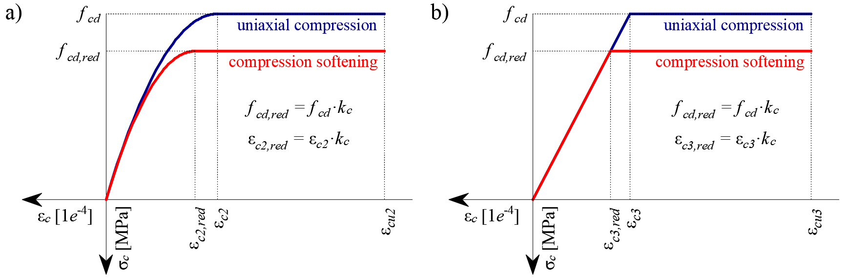
\[ \textsf{\textit{\footnotesize{Fig. 24\qquad Los diagramas tensión-deformación del hormigón para ELU: a) diagrama parábola-rectángulo; b) diagrama bilineal.}}}\]
La implementación del CSFM en IDEA StatiCa Detail no considera un criterio de fallo explícito en términos de deformaciones para el hormigón en compresión (es decir, una vez alcanzada la tensión máxima, considera una rama plástica con εcu2 (εcu3) con un valor del 5%, mientras que EN 1992-1-1 asume una deformación última inferior al 0,35%). Esta simplificación no permite verificar la capacidad de deformación de las estructuras que fallan a compresión. Sin embargo, su capacidad última fcd según EN 1992-1-1 3.1.3 se predice correctamente cuando, además del factor de hormigón fisurado (kc2 definido en (Fig. 25)), se considera el aumento de la fragilidad del hormigón a medida que aumenta su resistencia mediante el factor de reducción \(\eta_{fc}\) definido en el fib Model Code 2010 de la siguiente manera:
\[f_{cd}={\alpha_{cc}} \cdot \frac{f_{ck,red}}{γ_c} = {\alpha_{cc}} \cdot \frac{k_c \cdot f_{ck}}{γ_c} = {\alpha_{cc}} \cdot \frac{\eta _{fc} \cdot k_{c2} \cdot f_{ck}}{γ_c}\]
\[{\eta _{fc}} = {\left( {\frac{{30}}{{{f_{ck}}}}} \right)^{\frac{1}{3}}} \le 1\]
donde:
αcc es el coeficiente que tiene en cuenta los efectos a largo plazo sobre la resistencia a compresión y los efectos desfavorables derivados de la forma en que se aplica la carga. Se determina según EN 1992-1-1 Cl. 3.1.6 (1). El valor por defecto es 1,0.
kc es el factor de reducción global de la resistencia a compresión
kc2 es el factor de reducción debido a la presencia de fisuración transversal
fck es la resistencia característica del hormigón en probeta cilíndrica (en MPa para la definición de \( \eta_{fc} \)).
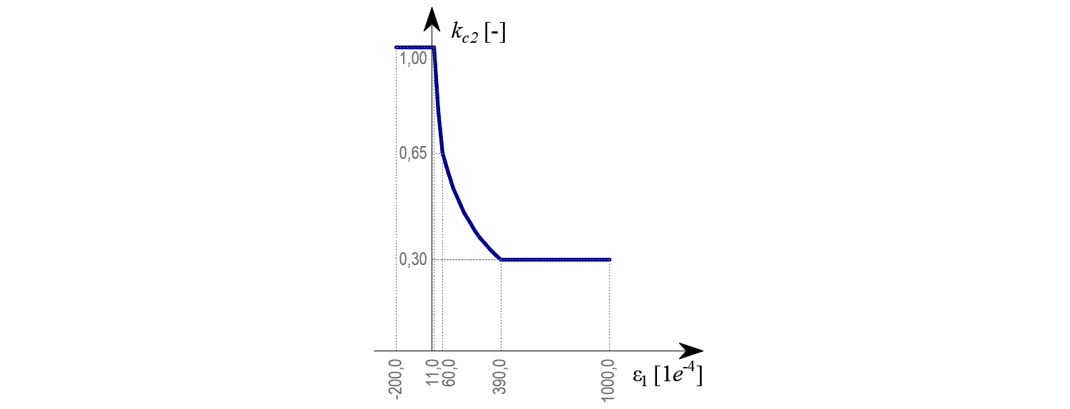
\[ \textsf{\textit{\footnotesize{Fig. 25\qquad La ley de ablandamiento a compresión.}}}\]
Hormigón - ELS
El análisis en servicio contiene ciertas simplificaciones de los modelos constitutivos que se utilizan para el análisis en estado límite último. La rama plástica del diagrama tensión-deformación del hormigón en compresión se desprecia, mientras que la rama elástica es lineal e infinita. La ley de ablandamiento a compresión no se considera. Estas simplificaciones mejoran la estabilidad numérica y la velocidad de cálculo, y no reducen la generalidad de la solución siempre que los límites de tensión resultantes en los materiales en servicio estén claramente por debajo de sus puntos de plastificación (como exige el Eurocódigo). Por tanto, los modelos simplificados utilizados para el estado de servicio solo son válidos si se cumplen todos los requisitos de verificación.
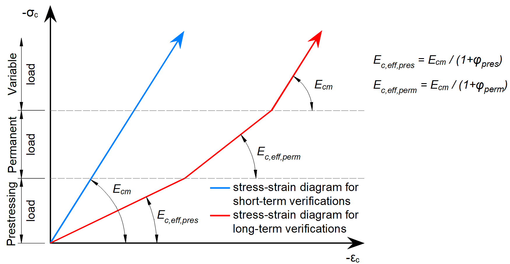
\[ \textsf{\textit{\footnotesize{Fig. 26\qquad Diagramas tensión-deformación del hormigón implementados para el análisis en servicio: verificaciones a corto y largo plazo.}}}\]
Efectos a largo plazo
En el análisis en servicio, los efectos a largo plazo del hormigón se consideran utilizando un coeficiente de fluencia efectivo infinito (\(\varphi\), tomado con un valor de 2,5 por defecto) que modifica el módulo de elasticidad secante del hormigón (Ecm) según EN 1992-1-1, sección 3.1.4 (3) resp. 7.4.3 (5) de la siguiente manera:
\[E_{c,eff} = \frac{E_{cm}}{1+\varphi}\]
Al considerar los efectos a largo plazo, primero se calcula un escalón de carga con todas las cargas permanentes teniendo en cuenta el coeficiente de fluencia (es decir, utilizando el módulo de elasticidad efectivo del hormigón, Ec,eff) y, a continuación, las cargas adicionales se calculan sin el coeficiente de fluencia (es decir, utilizando Ecm). Además, para realizar las verificaciones a corto plazo, se efectúa otro cálculo en el que todas las cargas se calculan sin el coeficiente de fluencia. Ambos cálculos para las verificaciones a largo y corto plazo se representan en la Fig. 26.
Los factores de fluencia son definidos por el usuario en las propiedades del material y deben calcularse según EN 1992-1-1, Fig. 3.1.
Armadura
Por defecto, se considera el diagrama tensión-deformación bilineal idealizado para las barras de armadura desnudas definido en EN 1992-1-1, sección 3.2.7 (Fig. 27). La definición de este diagrama solo requiere conocer las propiedades básicas de la armadura durante la fase de diseño (resistencia y clase de ductilidad). Cuando se conozca, se puede considerar la relación tensión-deformación real de la armadura (laminada en caliente, trabajada en frío, templada y revenida en línea, …). El diagrama tensión-deformación de la armadura puede ser definido por el usuario, pero en este caso no es posible asumir el efecto de rigidización a tracción (no es posible calcular la anchura de fisura). El uso del diagrama tensión-deformación con rama superior horizontal no permite verificar la durabilidad estructural. Por tanto, es necesaria la verificación manual de los requisitos normativos de ductilidad.
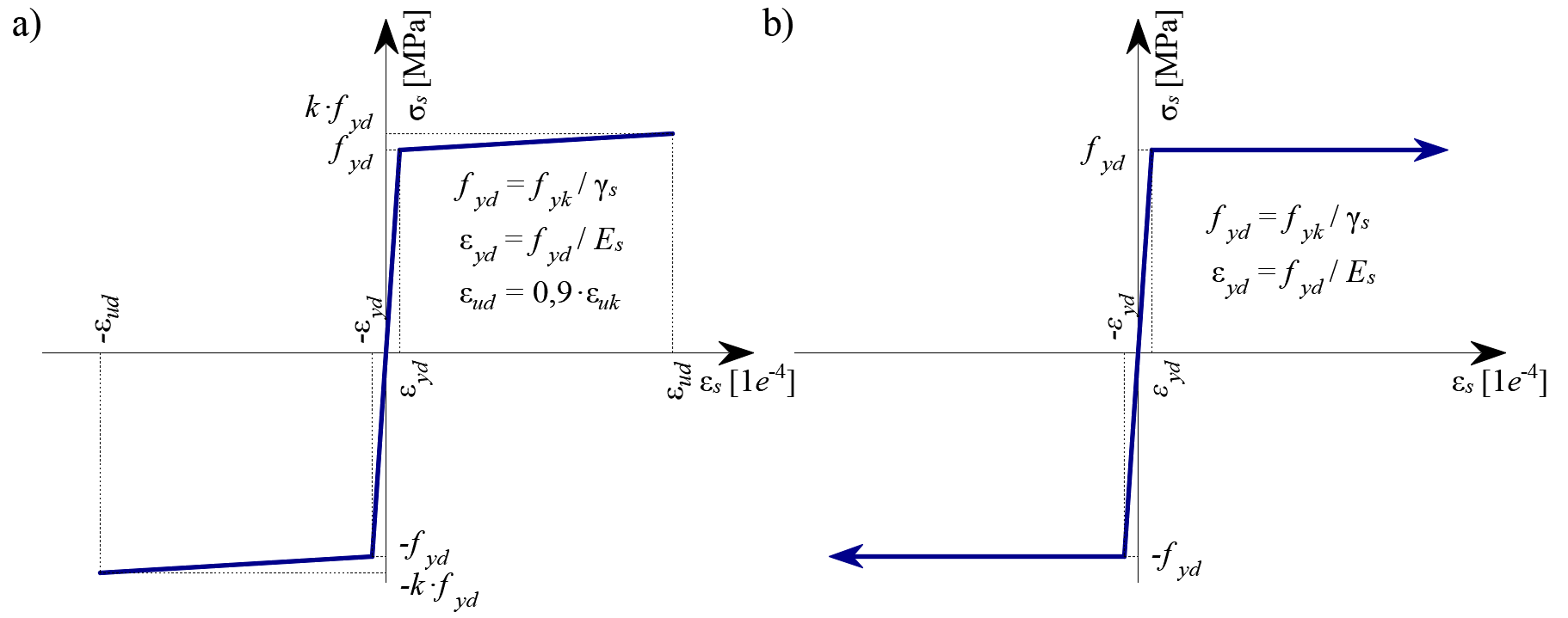
\( \textsf{\textit{\footnotesize{Fig. 27 \qquad Diagrama tensión-deformación de la armadura: a) diagrama bilineal con rama superior inclinada; b) diagrama bilineal}}}\) \( \textsf{\textit{\footnotesize{con rama superior horizontal.}}}\)
La rigidización a tracción (Fig. 28) se tiene en cuenta automáticamente modificando la relación tensión-deformación de entrada de la barra de armadura desnuda con el fin de capturar la rigidez media de las barras embebidas en el hormigón (εm).
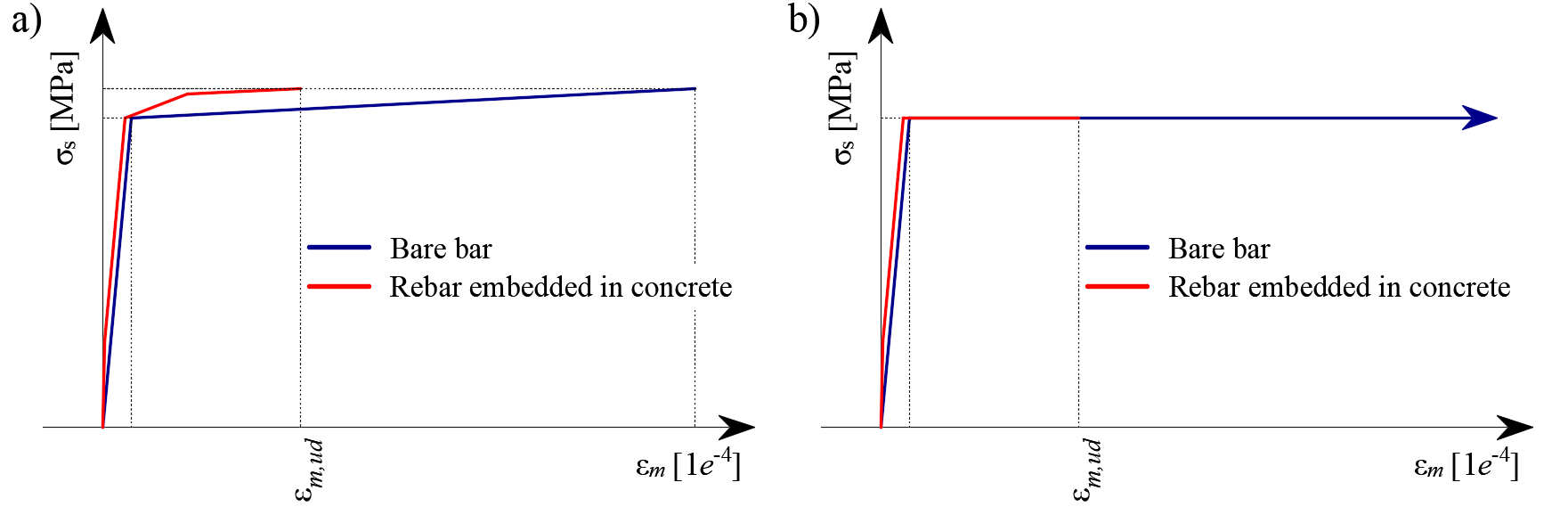
\[ \textsf{\textit{\footnotesize{Fig. 28\qquad Esquema de la rigidización a tracción.}}}\]
4.2 Factores de seguridad
El Método del Campo de Tensiones Compatible cumple con los códigos de diseño modernos. Como los modelos de cálculo solo utilizan propiedades de material estándar, el formato de factor de seguridad parcial prescrito en los códigos de diseño puede aplicarse sin ninguna adaptación. De este modo, las cargas de entrada se mayoran y las propiedades características del material se reducen mediante los coeficientes de seguridad respectivos prescritos en los códigos de diseño, exactamente igual que en el análisis convencional de hormigón. Los valores de los factores de seguridad del material prescritos en EN 1992-1-1 cap. 2.4.2.4 se establecen por defecto, pero el usuario puede modificar los factores de seguridad en los ajustes de Código y cálculo (Fig. 29).
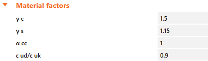
\[ \textsf{\textit{\footnotesize{Fig. 29\qquad The setting of material safety factors in Idea StatiCa Detail.}}}\]
Los factores de seguridad de las cargas deben ser definidos por el usuario en las Reglas de combinación para cada combinación no lineal de casos de carga (Fig. 30). Para todas las plantillas implementadas en Idea StatiCa Detail, los factores de seguridad parciales ya están predefinidos.
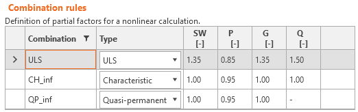
\[ \textsf{\textit{\footnotesize{Fig. 30\qquad The setting of load partial factors in Idea StatiCa Detail.}}}\]
Mediante el uso de combinaciones de factores de seguridad parciales definidas por el usuario, los usuarios también pueden calcular con el CSFM utilizando el método del factor de resistencia global (Navrátil, et al. 2017), aunque este enfoque apenas se utiliza en la práctica del diseño. Algunas guías recomiendan el uso del método del factor de resistencia global para el análisis no lineal. Sin embargo, en análisis no lineales simplificados (como el CSFM), que solo requieren las propiedades del material empleadas en los cálculos manuales convencionales, sigue siendo más deseable utilizar el formato de seguridad parcial.
4.3 Análisis del estado límite último
Las diferentes verificaciones requeridas por EN 1992-1-1 se evalúan a partir de los resultados directos proporcionados por el modelo. Las verificaciones ELU se realizan para la resistencia del hormigón, la resistencia de la armadura y el anclaje (tensiones tangenciales de adherencia).
La resistencia del hormigón a compresión se evalúa como la relación entre la tensión principal máxima de compresión σc = σc2 obtenida del análisis por elementos finitos y el valor límite σc,lim = fcd.
La resistencia de la armadura se evalúa tanto a tracción como a compresión como la relación entre la tensión en la armadura en las fisuras σsr y el valor límite especificado σs,lim:
\(σ_{s,lim} = \frac{k \cdot f_{yk}}{γ_s}\qquad\qquad\textsf{\small{for bilinear diagram with inclined top branch}}\)
\(σ_{s,lim} = \frac{f_{yk}}{γ_s}\qquad\qquad\,\,\,\,\textsf{\small{for bilinear diagram with horizontal top branch}}\)
donde:
fyk límite elástico de la armadura según EN 1992-1-1 Cl. 3.2.3,
k la relación entre la resistencia a tracción ftk y el límite elástico,
\(k = \frac{f_{tk}}{f_{yk}}\)
γs es el coeficiente parcial de seguridad de la armadura
La tensión tangencial de adherencia se evalúa de forma independiente como la relación entre la tensión de adherencia τb calculada mediante el análisis por elementos finitos y la resistencia última de adherencia fbd, según EN 1992-1-1 cap. 8.4.2:
\[\frac{τ_{b}}{f_{bd}}\]
\[f_{bd} = 2.25 \cdot η_1\cdot η_2\cdot f_{ctd}\]
donde:
fctd es el valor de cálculo de la resistencia a tracción del hormigón según EN 1992-1-1 Cl. 3.1.6 (2). Debido a la mayor fragilidad de los hormigones de mayor resistencia, fctk,0.05 se limita al valor correspondiente a C60/75 según EN 1992-1-1 Cl. 8.4.2 (2)
η1 es un coeficiente relacionado con la calidad de las condiciones de adherencia y la posición de la barra durante el hormigonado (Fig. 31).
η1 = 1,0 cuando se obtienen condiciones de adherencia «buenas» y
η1 = 0,7 para todos los demás casos y para barras en elementos estructurales construidos con encofrado deslizante, salvo que pueda demostrarse que existen condiciones de adherencia «buenas»
η2 está relacionado con el diámetro de la barra:
η2 = 1,0 para Ø ≤ 32 mm
η2 = (132 - Ø)/100 para Ø > 32 mm
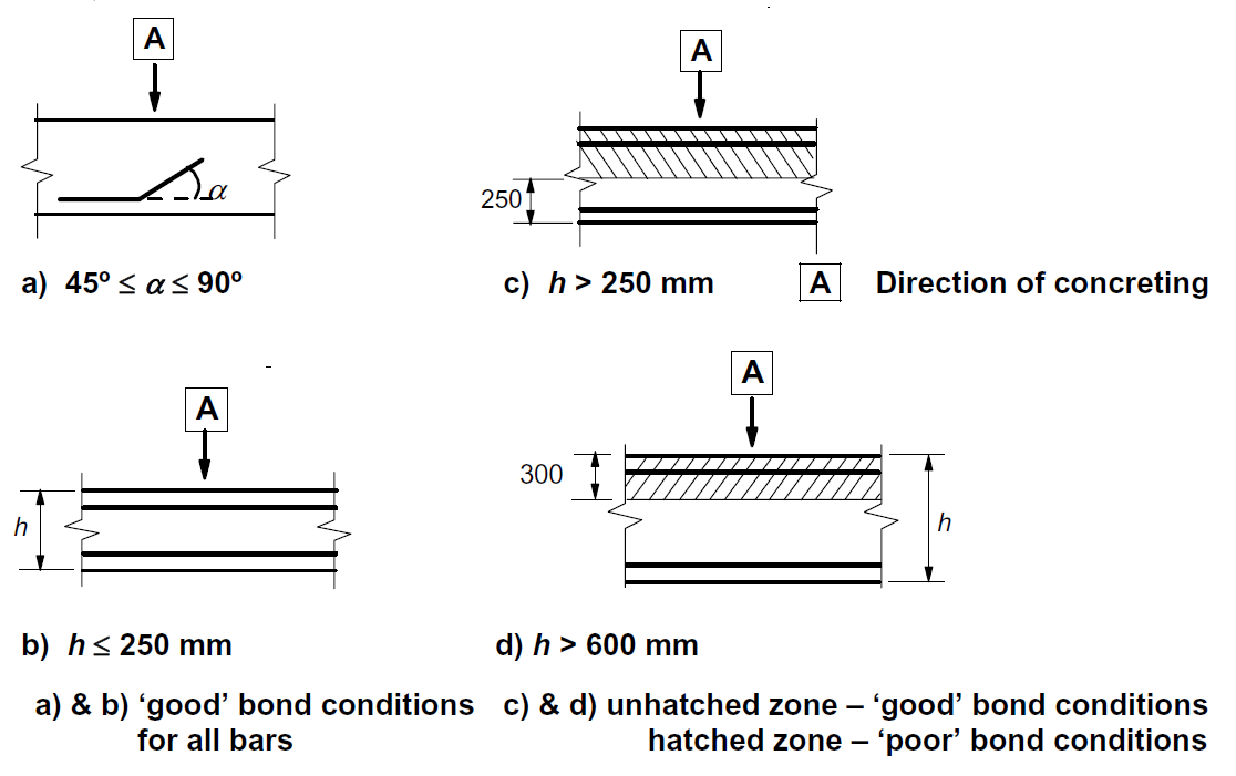
\[ \textsf{\textit{\footnotesize{Fig. 31\qquad EN 1992-1-1 Figure 8.2 - Description of bond conditions.}}}\]
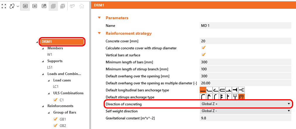
En IDEA StatiCa Detail las condiciones de adherencia se tienen en cuenta según la Fig. 31 c) y d). La dirección del hormigonado puede establecerse en la aplicación para cada elemento del proyecto de la siguiente manera.
Estas verificaciones se realizan con respecto a los valores límite apropiados para las partes correspondientes de la estructura (es decir, a pesar de tener un único grado tanto para el hormigón como para el material de la armadura, los diagramas tensión-deformación finales diferirán en cada parte de la estructura debido a los efectos de rigidización a tracción y ablandamiento a compresión).
También existe la opción de modelar barras lisas. Puede encontrarse más información aquí: Barras lisas en Detail
Fuerza total Ftot y fuerza límite Flim
La fuerza total Ftot es un resultado del análisis por elementos finitos y puede definirse de dos maneras.
\[F_{tot}=A_{s}\cdot \sigma_{s}\]
donde As es el área de la barra de armadura y σs es la tensión en la barra.
O como la suma de la fuerza de anclaje Fa y la fuerza de adherencia Fbond.
\[F_{tot}=F_{a}+F_{bond}\]
donde Fa es la fuerza real en el muelle de anclaje y Fbond es la fuerza de adherencia que puede obtenerse integrando la tensión de adherencia τb a lo largo de la longitud de la barra de armadura l.
\[F_{bond}=C_{s} \cdot \int_{0}^{l}\tau_{b}\left( x \right)dx\]
Cs es el perímetro de la barra de armadura.
La fuerza límite Flim es la fuerza máxima en el elemento de la barra considerando la resistencia última de la barra y también las condiciones de anclaje (adherencia entre el hormigón y la armadura y ganchos de anclaje, lazos, etc.).
\[F_{lim}=min\left( F_{lim,bond}+F_{au},F_{u} \right)\]
\[F_{u}=k\cdot f_{yd}\cdot A_{s}\]
\[F_{au}=\beta\cdot k\cdot f_{yd}\cdot A_{s}\]
\[F_{lim,bond}=C_{s}\cdot l \cdot f_{bd}\]
donde Cs es el perímetro de la barra de armadura y l es la longitud desde el inicio de la barra hasta el punto de interés.
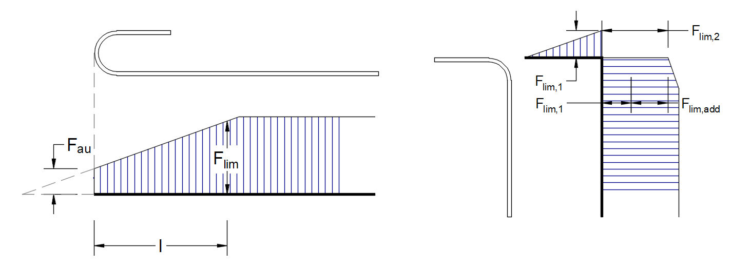
\[ \textsf{\textit{\footnotesize{Fig. 32\qquad Definition of the limit force Flim}}}\]
\[F_{lim,2}=F_{lim,1}+F_{lim,add}\]
donde Flim,add es la fuerza adicional calculada a partir de la magnitud del ángulo entre elementos adyacentes. Flim,2 debe ser siempre inferior a Fu.
Los tipos de anclaje disponibles en el CSFM incluyen barra recta (es decir, sin reducción en el extremo de anclaje), patilla, gancho, lazo, barra transversal soldada, adherencia perfecta y barra continua. Todos estos tipos, junto con los coeficientes de anclaje β respectivos, se muestran en la Fig. 32 para la armadura longitudinal y en la Fig. 33 para los estribos. Los valores de los coeficientes de anclaje adoptados están de acuerdo con EN 1992-1-1 sección 8.4.4 Tab. 8.2. Cabe señalar que, a pesar de las diferentes opciones disponibles, el CSFM distingue tres tipos de extremos de anclaje: (i) sin reducción en la longitud de anclaje, (ii) una reducción del 30 % de la longitud de anclaje en el caso de un anclaje normalizado y (iii) adherencia perfecta.

\[ \textsf{\textit{\footnotesize{Fig. 33\qquad Available anchorage types and respective anchorage coefficients for longitudinal reinforcing bars in the CSFM:}}}\]
\[ \textsf{\textit{\footnotesize{(a) straight bar; (b) bend; (c) hook; (d) loop; (e) welded transverse bar; (f) perfect bond; (g) continuous bar.}}}\]
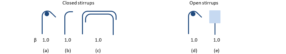
\[ \textsf{\textit{\footnotesize{Fig. 33\qquad Available anchorage types and respective anchorage coefficients for stirrups.}}}\]
\[ \textsf{\textit{\footnotesize{Closed stirrups: (a) hook; (b) bend; (c) overlap. Open stirrups: (d) hook; (e) continuous bar.}}}\]
Para cumplir con EN 1992-1-1, debe utilizarse el muelle de anclaje en el cálculo; dicho muelle se modifica mediante el coeficiente β, por lo que el usuario debe utilizar uno de los tipos de anclaje disponibles al definir las condiciones de inicio y fin de la armadura.
4.4 Áreas parcialmente cargadas (PLA)
Al diseñar estructuras de hormigón, nos encontramos con dos grandes grupos de áreas parcialmente cargadas (PLA): el primero comprende los apoyos, mientras que el otro consiste en las zonas de anclaje. De acuerdo con las normas actualmente vigentes para el diseño de estructuras de hormigón armado EN 1992-1-1 cap. 6.7 (Fig. 34), el aplastamiento local del hormigón y las fuerzas de tracción transversales deben considerarse para las áreas parcialmente cargadas. Para una carga uniformemente distribuida sobre un área, Ac0, la capacidad a compresión del hormigón puede incrementarse hasta tres veces en función del área de distribución de cálculo Ac1.
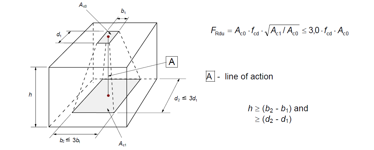
\[ \textsf{\textit{\footnotesize{Fig. 34\qquad Partially loaded areas according to EN 1992-1-1.}}}\]
El área parcialmente cargada debe estar suficientemente armada con armadura transversal diseñada para transmitir las fuerzas de estallido que se producen en la zona. Para el diseño de la armadura transversal en áreas parcialmente cargadas, se utiliza el método Biela-y-tirante según el Eurocódigo. Sin la armadura transversal requerida, no es posible considerar el incremento de la capacidad a compresión del hormigón.
Áreas parcialmente cargadas en el CSFM
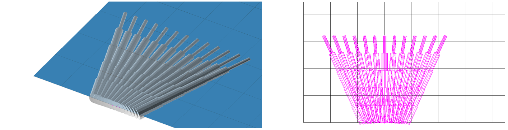
\[ \textsf{\textit{\footnotesize{Fig. 35\qquad Fictitious struts with concrete finite element mesh.}}}\]
Mediante el CSFM, es posible diseñar y verificar estructuras de hormigón armado incluyendo la influencia del incremento de la resistencia a compresión del hormigón en áreas parcialmente cargadas. Dado que el CSFM es un modelo de lámina (2D) y las áreas parcialmente cargadas son una tarea espacial (3D), fue necesario encontrar una solución que combinara estos dos tipos de tareas diferentes (Fig. 35). Si se activa la función "áreas parcialmente cargadas", la geometría del cono admisible se crea según el Eurocódigo (Fig. 34). Todas las colisiones geométricas se resuelven completamente en 3D para la geometría del elemento de hormigón especificada y las dimensiones de cada PLA. Posteriormente, se crea un modelo de cálculo del área parcialmente cargada.
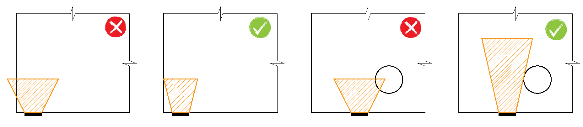
\[ \textsf{\textit{\footnotesize{Fig. 36\qquad Allowable cone geometries.}}}\]
La modificación del modelo de material resultó ser un enfoque inadecuado, principalmente porque la asignación de propiedades a la malla de elementos finitos es problemática. Se determinó que un enfoque independiente de la malla de elementos finitos es una solución más apropiada. Se crean bielas ficticias absolutamente coherentes para la geometría conocida del cono de compresión (Fig. 35 y Fig. 37). Estas bielas tienen propiedades de material idénticas al hormigón utilizado en el modelo, incluido el diagrama tensión-deformación. La forma del cono determina la dirección de las bielas, que distribuye gradualmente la carga sobre la PLA hacia el área de distribución de cálculo. La densidad superficial de las bielas ficticias es variable en cada parte del cono y añade un área ficticia de hormigón en la dirección de la carga. A nivel del área cargada (Ac0), se añade un área ficticia de hormigón según la relación \(\sqrt{A_{c0} \cdot A_{c1}} - A_{real}\) (donde Areal es el área del apoyo considerada en el modelo de cálculo 2D), y esta área disminuye linealmente hasta cero hacia el área de distribución de cálculo (Ac1). Esta solución garantiza que la tensión de compresión en el hormigón sea constante en todo el volumen del cono.
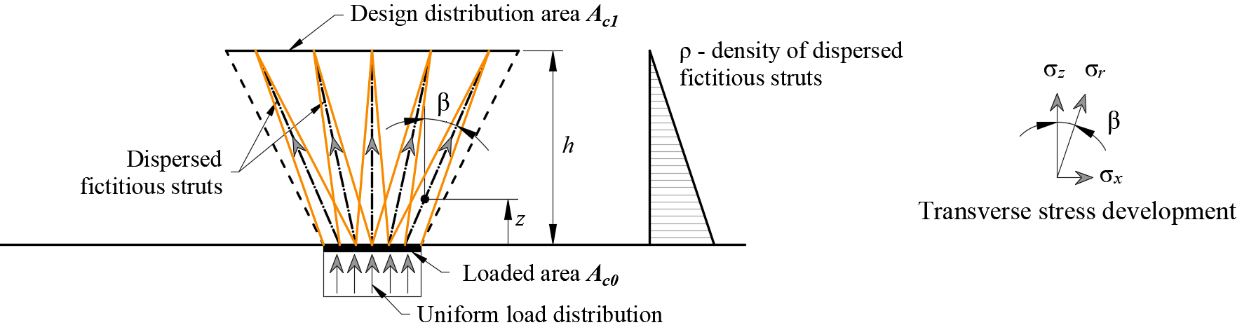
\[\rho \left( {\beta ,z} \right) = \left( {\sqrt {\frac{A_{c1}}{A_{c0}}} - \frac{A_{real}}{A_{c0}}} \right)\,\cdot\,\left( {1 - \frac{z}{h}} \right)\,\cdot\,\frac{1}{{\cos \beta }}\]
\[ \textsf{\textit{\footnotesize{Fig. 37\qquad Fictitious struts in the computational model}}}\]
La resistencia del área parcialmente cargada se incrementa según la relación entre el área distribuida de cálculo y el área cargada establecida en EN 1992-1-1 (6.7). Debe tenerse en cuenta que se trata de un modelo de cálculo que no puede describir con precisión el estado tensional sobre un área parcialmente cargada, cuyo flujo real es mucho más complejo. Sin embargo, esta solución permite la distribución correcta de la carga a todo el modelo respetando la mayor capacidad de carga del área parcialmente cargada. Además, introduce correctamente las tensiones transversales en esta zona.
Al utilizar la función de áreas parcialmente cargadas para simular el incremento de la capacidad a compresión del hormigón, es necesario realizar la verificación normativa por separado según EN 1992-1-1, sección 6.7 (2). Las fuerzas de tracción transversales (fuerzas de hendimiento) transmitidas por la armadura se verifican automáticamente.
4.5 Análisis del estado límite de servicio
Las verificaciones en ELS se realizan para la limitación de tensiones, la anchura de fisura y los límites de deformación. Las tensiones se verifican en los elementos de hormigón y armadura según EN 1992-1-1 de manera similar a la especificada para el ELU.
Limitación de tensiones
La tensión de compresión en el hormigón deberá limitarse para evitar fisuras longitudinales. Según EN 1992-1-1 cap. 7.2 (2), pueden producirse fisuras longitudinales si el nivel de tensión bajo la combinación característica de cargas supera el valor k1fck. La tensión de compresión en el hormigón se evalúa como la relación entre la tensión principal máxima de compresión σc = σc2 obtenida del análisis por elementos finitos para los estados límite de servicio y el valor límite σc,lim. Entonces:
\[\frac{σ_{c}}{σ_{c,lim}}\]
\[σ_{c,lim} = k_1\cdot f_{ck}\]
donde:
fck resistencia característica a compresión en probeta cilíndrica del hormigón,
k1 =0.6.
Si la tensión en el hormigón bajo las cargas cuasipermanentes es inferior a k2fck según EN 1992-1-1 Cl. 7.2(3), puede asumirse fluencia lineal. Si la tensión en el hormigón supera k2fck, deberá considerarse la fluencia no lineal (véase EN 1992-1-1 Cl. 3.1.4). En IDEA StatiCa Detail solo puede asumirse la fluencia lineal según EN 1992-1-1 Cl. 3.1.4 (3) (véase Modelos de material (EN)).
Puede asumirse que se evita una fisuración o deformación inaceptable si, bajo la combinación característica de cargas, la tensión de tracción en la armadura no supera k3fyk (EN 1992-1-1 cap. 7.2 (5)). La resistencia de la armadura se evalúa como la relación entre la tensión en la armadura en las fisuras σs = σsr y el valor límite especificado σs,lim:
\[\frac{σ_{s}}{σ_{s,lim}}\]
\[σ_{s,lim} = k_3\cdot f_{yk}\]
donde:
fyk límite elástico de la armadura,
k3 =0.8.
Deformación
Las deformaciones solo pueden evaluarse para muros o vigas isostáticas (estáticamente determinadas) o hiperestáticas (estáticamente indeterminadas). En estos casos, se considera el valor absoluto de las deformaciones (comparado con el estado inicial antes de la carga), y el usuario debe establecer el valor máximo admisible de las deformaciones. Las deformaciones en los extremos recortados no pueden verificarse, ya que se trata esencialmente de estructuras inestables en las que el equilibrio se satisface añadiendo fuerzas en los extremos, por lo que las deformaciones no son realistas. Puede calcularse y verificarse la deformación a corto plazo uz,st o a largo plazo uz,lt frente a los valores límite definidos por el usuario:
\[\frac{u_ z}{u_{z,lim}}\]
donde:
uz deformación a corto o largo plazo calculada mediante análisis por elementos finitos,
uz,lim valor límite de la deformación definido por el usuario.
Anchura de fisura
Las anchuras y orientaciones de fisura se calculan únicamente para efectos a largo plazo (utilizando Ec,eff) para las combinaciones en las que está habilitada la evaluación de la anchura de fisura. Las verificaciones basadas en los valores límite especificados por el usuario de acuerdo con el Eurocódigo se presentan de la siguiente manera:
\[\frac{w}{w_{lim}}\]
donde:
w anchura de fisura calculada mediante análisis por elementos finitos,
wlim valor límite de la anchura de fisura definido por el usuario.
Existen dos formas de calcular las anchuras de fisura (fisuración estabilizada y no estabilizada). En el caso general (fisuración estabilizada), la anchura de fisura se calcula integrando las deformaciones en los elementos 1D de las barras de armadura. La dirección de la fisura se calcula a partir de los tres puntos de integración más cercanos (al centro del elemento finito 1D de armadura dado) de los elementos 2D de hormigón. Aunque este enfoque para calcular las direcciones de fisura no se corresponde con la posición real de las fisuras, proporciona valores representativos que conducen a resultados de anchura de fisura comparables con los valores de anchura de fisura requeridos por la normativa en la posición de la barra de armadura.
5 Verificaciones estructurales según ACI 318-19
La evaluación de la estructura mediante CSFM se realiza mediante dos análisis diferentes: uno para las combinaciones de carga en servicio y otro para las combinaciones de carga de resistencia. El análisis en servicio asume que el comportamiento bajo cargas mayoradas es satisfactorio y que las condiciones de plastificación del material no se alcanzarán en los niveles de carga de servicio. Este enfoque permite el uso de modelos constitutivos simplificados (con una rama lineal del diagrama tensión-deformación del hormigón) para el análisis en servicio, con el fin de mejorar la estabilidad numérica y la velocidad de cálculo.
El CSFM está de acuerdo con ACI 318-19, apartado 6.8.1.1. Para que el CSFM cumpla los requisitos del apartado 6.8.1.2 de ACI 318-19, se realizaron numerosos ensayos de verificación en diversas universidades. Los artículos individuales que resumen los resultados de verificación y validación pueden consultarse en el siguiente enlace.
5.1 Modelos de material (ACI)
Hormigón - Resistencia
El modelo de hormigón implementado para los cálculos de resistencia en CSFM se basa en la curva tensión-deformación parabólico-plástica para el hormigón, basada en la curva tensión-deformación parabólica de la Portland Cement Association descrita en las Notas de la PCA sobre los Requisitos del Código de Construcción ACI 318-99 para Hormigón Estructural, Figura 6-8. La resistencia a tracción se desprecia, como ocurre en el diseño clásico de hormigón armado.
\[ \textsf{\textit{\footnotesize{Fig. 38\qquad The stress-strain diagram of concrete for Strength analysis}}}\]
La implementación de CSFM en IDEA StatiCa Detail no considera un criterio de rotura explícito en términos de deformaciones para el hormigón en compresión (es decir, una vez alcanzada la tensión máxima, considera una rama plástica con εc0 con un valor máximo del 5%, mientras que ACI 318-19 Cl. 22.2.2.1 asume una deformación última inferior al 0,3%). Esta simplificación no permite verificar la capacidad de deformación de las estructuras que fallan a compresión. Sin embargo, la resistencia se predice correctamente cuando, además del factor de hormigón fisurado (kc2 definido en la Fig. 39), se considera el aumento de la fragilidad del hormigón a medida que aumenta su resistencia mediante el factor de reducción \(\eta_{fc}\) definido en el fib Model Code 2010 de la siguiente manera:
\[f'_{c,lim}=\alpha_{1}\cdot\phi_{c}\cdot k_{c}\cdot f'_{c}\]
\[k_{c}=\eta_{fc}\cdot k_{c2}\]
\[{\eta _{fc}} = {\left( {\frac{{30}}{{{f'_{c}}}}} \right)^{\frac{1}{3}}} \le 1\]
donde:
α1 es el factor de reducción de la resistencia a compresión del hormigón definido en ACI 318-19 Cl. 22.2.2.4.1. Al utilizar un diagrama tensión-deformación parábola-rectángulo, es necesario reducir la tensión de compresión máxima mediante este factor. Esto promedia la distribución de tensiones en la zona comprimida de tal manera que la resistencia a compresión resultante es menor o igual a la resistencia a compresión calculada mediante un diagrama tensión-deformación con una rama plástica decreciente.
Φc es el factor de reducción de resistencia para el hormigón. El valor por defecto se establece según ACI 318-19 Tabla 24.2.1 (b)(f).
kc2 es el factor de reducción debido a la presencia de fisuración transversal.
f'c es la resistencia a compresión del hormigón en probeta cilíndrica (en MPa para la definición de \( \eta_{fc} \)).
\[ \textsf{\textit{\footnotesize{Fig. 39\qquad The compression softening law.}}}\]
kc2 es un factor de reducción basado en las mismas hipótesis que el coeficiente de zona nodal βn dado en ACI 318-19 Tabla 23.9.2, excepto que en CSFM, la presencia de una tensión principal de tracción perpendicular a la tensión principal de compresión se verifica para cada elemento finito (no solo para los nodos del modelo Biela y tirante).
Hormigón – Aptitud al servicio
El análisis de aptitud al servicio contiene ciertas simplificaciones de los modelos constitutivos utilizados para el análisis de resistencia. La rama plástica de la curva tensión-deformación del hormigón en compresión se desprecia, mientras que la rama elástica es lineal e ilimitada. La ley de ablandamiento a compresión no se considera. Estas simplificaciones mejoran la estabilidad numérica y la velocidad de cálculo, y no reducen la generalidad de la solución siempre que los límites de tensión del material resultante en servicio estén claramente por debajo de sus puntos de plastificación (según lo exigido por ACI). Por lo tanto, los modelos simplificados utilizados para la aptitud al servicio solo son válidos si se cumplen todos los requisitos de verificación.
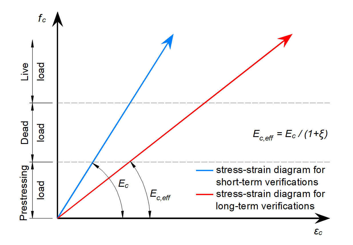
\[ \textsf{\textit{\footnotesize{Fig. 40\qquad Concrete stress-strain diagrams implemented for serviceability analysis: short- and long-term verifications.}}}\]
Efectos a largo plazo
El comportamiento a largo plazo de la estructura, como las flechas diferidas o el cálculo de anchos de fisura causados por cargas sostenidas, está influenciado por la fluencia del hormigón. ACI 318-19 en el párrafo 24.2.4.1.3 define el factor dependiente del tiempo para cargas sostenidas – ξ, que representa el efecto de la fluencia para una duración de carga sostenida especificada.
En la aplicación Detail, el módulo de elasticidad Ec se ajusta para determinar el comportamiento a largo plazo de la estructura mediante el factor ξ. El módulo de elasticidad ajustado se denomina Ec,eff – véase la Figura 40.
Suponiendo que la deformación del elemento se expresa mediante la deformación unitaria, se puede escribir que:
\[\epsilon_{tot} = \epsilon_{0} + \epsilon_{creep} = \epsilon_{0} \cdot (1+\xi)\]
donde:
ε0 es la deformación a corto plazo (sin la influencia de la fluencia) y εcreep es la deformación causada por la fluencia.
Aplicando la ley de Hooke, se puede escribir:
\[E_{c,eff} = \frac{f_{c}}{\epsilon_{tot}}\]
Sustituyendo \(\epsilon_{tot} = \epsilon_{0} \cdot (1+\xi)\) y \(\epsilon_{0} = f_{c} / E_{c}\) se obtiene:
\[E_{c,eff} = \frac{E_{c}}{1+\xi}\]
La duración de la carga sostenida para la determinación del factor ξ puede establecerse individualmente para cada combinación de servicio a largo plazo.
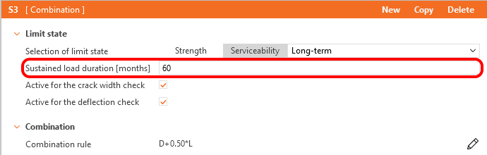
\[ \textsf{\textit{\footnotesize{Fig. 41\qquad Sustained load duration}}}\]
Las flechas, tensiones y anchos de fisura dependientes del tiempo se calculan entonces con un modelo de material modificado en el que el efecto del refinamiento a compresión se tiene en cuenta automáticamente por la naturaleza del análisis de elementos finitos. Por lo tanto, no es necesario multiplicarlos adicionalmente por el factor definido en 24.2.4.1.1.
Efectos a corto plazo
Para realizar las verificaciones a corto plazo, se efectúa otro cálculo en el que todas las cargas se calculan sin el factor dependiente del tiempo para cargas sostenidas. Ambos cálculos para las verificaciones a largo y corto plazo se representan en la Fig. 40.
Armadura
Se considera un diagrama tensión-deformación perfectamente elastoplástico con un límite elástico definido para la armadura no pretensada, véase ACI 319-19 CL. 20.2.1. La definición de este diagrama solo requiere conocer las propiedades básicas de la armadura: la resistencia y el módulo de elasticidad.
El diagrama tensión-deformación de la armadura también puede ser definido por el usuario, pero en este caso, no es posible asumir el efecto de rigidización a tracción (no es posible calcular el ancho de fisura).
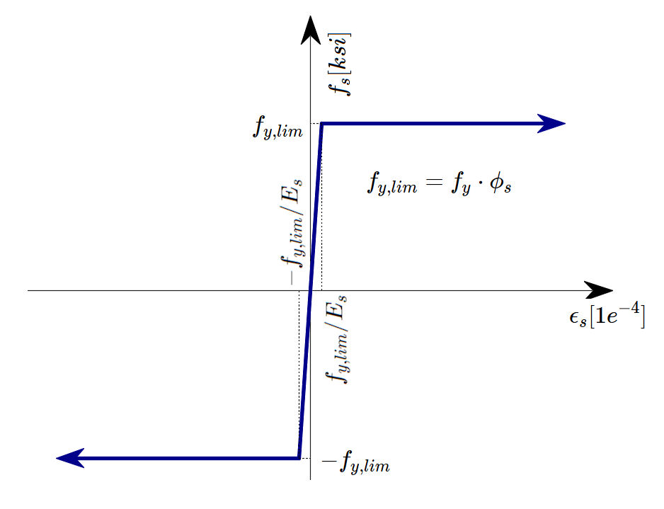
\[ \textsf{\textit{\footnotesize{Fig. 42 \qquad Stress-strain diagram of reinforcement}}}\]
donde:
Φs es el factor de reducción de resistencia para la armadura. El valor por defecto se establece según ACI 318-19 Tabla 24.2.1.
fy es la resistencia a la fluencia de la armadura
Es módulo de elasticidad de la armadura
El 10% se selecciona como la deformación límite a la que se detiene el cálculo. Esto se considera seguro según ASTM A955/A955M-20c Artículo 7.
La rigidización a tracción (Fig. 43) se tiene en cuenta automáticamente modificando la relación tensión-deformación de entrada de la barra de armadura desnuda con el fin de capturar la rigidez media de las barras embebidas en el hormigón (εm).
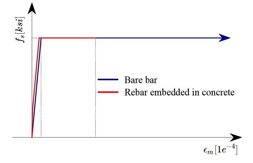
\[ \textsf{\textit{\footnotesize{Fig. 43\qquad Scheme of tension stiffening.}}}\]
5.2 Factores de reducción de resistencia y de carga
El Método del Campo de Tensiones Compatible cumple con los códigos de diseño modernos. Dado que los modelos de cálculo solo utilizan propiedades de los materiales estándar, el formato de coeficientes parciales de seguridad prescrito en los códigos de diseño puede aplicarse sin ninguna adaptación. De este modo, las cargas de entrada se mayorан y las propiedades características de los materiales se reducen mediante los respectivos factores de reducción de resistencia, exactamente como en el análisis convencional del hormigón.
Los valores de los factores de reducción de resistencia están prescritos en ACI 318-19 Cl. 21.2. Los valores por defecto para el hormigón y la armadura se eligen basándose en la suposición de que el ejemplo típico resuelto en la aplicación está controlado por cortante (según la Tabla 21.2.1 (b), (f), (g)). Sin embargo, es posible modelar cualquier tipo de elemento. Por lo tanto, si se evalúa un elemento controlado por compresión o tracción, el usuario tiene la opción de cambiar el valor del factor de reducción de resistencia en las Preferencias.
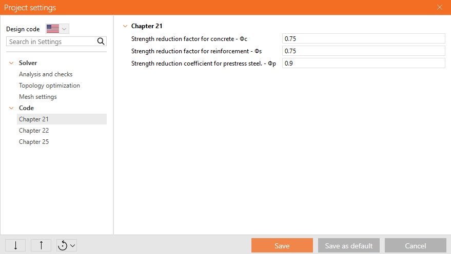
\[ \textsf{\textit{\footnotesize{Fig. 44\qquad The setting of strength reduction factors in IDEA StatiCa Detail.}}}\]
Factores de carga para combinaciones de Resistencia deberán definirse según ACI 318-19 Tabla 5.3.1.
Salvo lo indicado en el Capítulo 34, las combinaciones de carga a nivel de servicio no están definidas en ACI 318-19. Se recomienda utilizar reglas de combinación basadas en el Apéndice C de ASCE/SEI 7-16. Para todas las plantillas, los factores de carga ya están predefinidos.
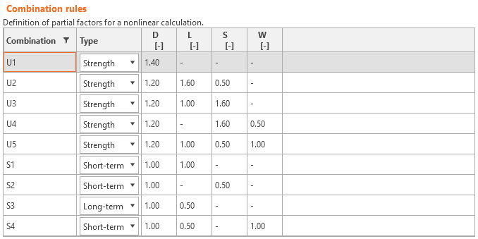
\[ \textsf{\textit{\footnotesize{Fig. 45\qquad The setting of load factors in Idea StatiCa Detail.}}}\]
5.3 Verificaciones de resistencia
Las diferentes verificaciones requeridas por ACI 318-19 se evalúan a partir de los resultados directos proporcionados por el modelo. Las verificaciones se realizan para la resistencia del hormigón, la resistencia de la armadura y el anclaje (tensiones tangenciales de adherencia).
La resistencia del hormigón a compresión se evalúa como la relación entre la tensión principal máxima de compresión fc (también σ2 en los resultados auxiliares) obtenida del análisis por elementos finitos y el valor límite f'c,lim.
La resistencia de la armadura se evalúa tanto a tracción como a compresión como la relación entre la tensión en la armadura en las fisuras fs y el valor límite especificado fy,lim.
La tensión tangencial de adherencia se evalúa de forma independiente como la relación entre la tensión de adherencia τb calculada mediante el análisis por elementos finitos y la resistencia de adherencia fbu.
Sin embargo, la norma ACI no aborda explícitamente la resistencia de adherencia, sino que trabaja con el cálculo de la denominada longitud de desarrollo, que se describe en la Sección 25.4.2. Dado que la resistencia de adherencia es un parámetro de entrada fundamental para determinar la longitud de desarrollo, véase R25.4.1.1 y ACI Committee 408 1966, la resistencia de adherencia puede calcularse de la siguiente manera:
Supongamos que si anclamos la barra de armadura en un bloque de hormigón hasta la longitud de desarrollo ld o mayor, el arranque de la armadura conducirá a la rotura de la armadura y no al arrancamiento del hormigón. Esto puede expresarse con la siguiente fórmula.
\[\pi\cdot d_{b} \cdot l_{d} \cdot f_{bu}=f_{y}\cdot A_{s}\]
donde:
db es el diámetro de la barra de armadura, ld es la longitud de desarrollo, fbu es la resistencia de adherencia, fy es el límite elástico de la armadura, y As es el área de la barra de armadura.
A partir de lo anterior, la fórmula para calcular la resistencia de adherencia puede derivarse fácilmente:
\[f_{bu}=\frac{f_{y}\cdot A_{s}}{\pi\cdot d_{b} \cdot l_{d} }\]
La longitud de desarrollo ld se determina según la Tabla 25.4.2.3 de ACI 318-19 de la siguiente manera:
\[l_{d}=\left( \frac{f_{y}\cdot\psi_{t}\cdot\psi_{e}\cdot\psi_{g}}{C\cdot\lambda\sqrt{f'_{c}}} \right)\cdot d_{b}\]
donde:
C = 25 (2,1 en sistema métrico) para barras del nº 6 e inferiores y alambres corrugados, C = 20 (1,7 en sistema métrico) para barras del nº 7 y superiores, λ = 1,0 para hormigón de peso normal, ψt, ψe, ψg se determinan según la Tabla 25.4.2.3 de ACI 318-19.
Solo se admite armadura sin revestimiento o con revestimiento de zinc (galvanizada), por lo que ψe = 1,0. ψg se determina automáticamente a partir del grado de la armadura, y ψt se deriva automáticamente de la posición de la armadura en el modelo y de la dirección del hormigonado, que puede establecerse en la aplicación para cada elemento del proyecto de la siguiente manera.
\[ \textsf{\textit{\footnotesize{Fig. 46\qquad Direction of concreting}}}\]
Estas verificaciones se llevan a cabo con respecto a los valores límite apropiados para las partes correspondientes de la estructura (es decir, a pesar de tener un único grado tanto para el hormigón como para el material de armadura, los diagramas tensión-deformación finales diferirán en cada parte de la estructura debido a los efectos de rigidización a tracción y ablandamiento a compresión).
También existe la opción de modelar barras lisas. Puede encontrarse más información aquí: Barras lisas en Detail
Fuerza total Ftot y fuerza límite Flim
La fuerza total Ftot es un resultado del análisis por elementos finitos y puede definirse de dos maneras.
\[F_{tot}=A_{s} \cdot f_{s}\]
donde As es el área de la barra de armadura y fs es la tensión en la barra.
O como suma de la fuerza de anclaje Fa y la fuerza de adherencia Fbond.
\[F_{tot}=F_{a}+F_{bond}\]
donde Fa es la fuerza real en el muelle de anclaje y Fbond es la fuerza de adherencia que puede obtenerse integrando la tensión de adherencia τb a lo largo de la longitud de la barra de armadura l.
\[F_{bond}=C_{s} \cdot \int_{0}^{l}\tau_{b}\left( x \right)dx\]
Cs es el perímetro de la barra de armadura.
La fuerza límite Flim es la fuerza máxima en el elemento de la barra considerando la resistencia de la barra y también las condiciones de anclaje (adherencia entre el hormigón y la armadura y ganchos de anclaje, lazos, etc.).
\[F_{lim}=min\left( F_{lim,bond}+F_{au},F_{u} \right)\]
\[F_{u}=f_{y,lim}\cdot A_{s}\]
\[F_{au}=\beta\cdot f_{y,lim}\cdot A_{s}\]
\[F_{lim,bond}=C_{s}\cdot l \cdot f_{bu}\]
donde Cs es el perímetro de la barra de armadura y l es la longitud desde el inicio de la barra hasta el punto de interés.
\[ \textsf{\textit{\footnotesize{Fig. 47\qquad Definition of the limit force Flim}}}\]
\[F_{lim,2}=F_{lim,1}+F_{lim,add}\]
donde Flim,add es la fuerza adicional calculada a partir de la magnitud del ángulo entre elementos adyacentes. Flim,2 debe ser siempre inferior a Fu.
Los tipos de anclaje disponibles en CSFM incluyen barra recta (es decir, sin reducción en el extremo de anclaje), gancho a 90 grados, gancho a 180 grados, adherencia perfecta y barra continua. Todos estos tipos, junto con los coeficientes de anclaje β respectivos, se muestran en la Fig. 48 para la armadura longitudinal. Los valores de los coeficientes de anclaje adoptados se derivan de la comparación de la ecuación del apartado ACI 318-19 25.4.3.1 y las ecuaciones tomadas del apartado ACI 318-19 25.4.2.3. Cabe señalar que, a pesar de las diferentes opciones disponibles, CSFM distingue tres tipos de extremos de anclaje: (i) sin reducción en la longitud de anclaje, (ii) una reducción del 30% de la longitud de anclaje en el caso de un anclaje normalizado, y (iii) adherencia perfecta.

\[ \textsf{\textit{\footnotesize{Fig. 48\qquad Available anchorage types and respective anchorage coefficients for longitudinal reinforcing bars in CSFM:}}}\]
\[ \textsf{\textit{\footnotesize{(a) straight bar; (b) 90-degree hook; (c) 180-degree hook; (d) perfect bond; (e) continuous bar}}}\]
El coeficiente de anclaje para los estribos es siempre β = 1,0.
Para cumplir con ACI, debe utilizarse el muelle de anclaje en el cálculo; el muelle de anclaje se modifica mediante el coeficiente β, por lo que el usuario debe utilizar uno de los tipos de anclaje disponibles al definir las condiciones de inicio y fin de la armadura.
5.4 Zonas de apoyo y anclaje – Áreas parcialmente cargadas
Al diseñar estructuras de hormigón, nos encontramos con dos grandes grupos de áreas parcialmente cargadas (APC): el primero comprende los apoyos, mientras que el otro consiste en las zonas de anclaje.
De acuerdo con las normas actualmente vigentes para el diseño de estructuras de hormigón armado ACI 318-19 cap. 22.8, se deben considerar el aplastamiento local del hormigón y las fuerzas de tracción transversales para los apoyos. Para una carga uniformemente distribuida sobre un área, Ac1, la capacidad a compresión del hormigón puede incrementarse hasta dos veces en función del área de distribución de cálculo Ac2. Véase la tabla 22.8.3.2 de ACI 318-19.
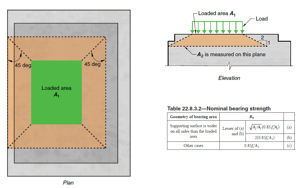
\[ \textsf{\textit{\footnotesize{Fig. 49\qquad Partially loaded areas for bearings according to ACI 318-19}}}\]
Para las zonas de anclaje postensadas, se debe seguir el ACI 318-19 cap. 25.9.
El área parcialmente cargada debe estar suficientemente armada con armadura transversal diseñada para transmitir las fuerzas de fisuración que se producen en la zona. Sin la armadura transversal requerida, no es posible considerar el incremento de la capacidad a compresión del hormigón.
Áreas parcialmente cargadas en CSFM
\[ \textsf{\textit{\footnotesize{Fig. 50\qquad Fictitious struts with concrete finite element mesh.}}}\]
Mediante CSFM, es posible diseñar y verificar estructuras de hormigón armado incluyendo la influencia del incremento de la resistencia a compresión del hormigón en áreas parcialmente cargadas. Dado que CSFM es un modelo de lámina (2D) y las áreas parcialmente cargadas son una tarea espacial (3D), fue necesario encontrar una solución que combinara estos dos tipos de tareas diferentes (Fig. 50). Si se activa la función "áreas parcialmente cargadas", la geometría del cono admisible se crea según el ACI (Fig. 49). Todas las colisiones geométricas se resuelven completamente en 3D para la geometría del elemento de hormigón especificada y las dimensiones de cada APC. Posteriormente, se crea un modelo de cálculo del área parcialmente cargada.
\[ \textsf{\textit{\footnotesize{Fig. 51\qquad Allowable cone geometries.}}}\]
La modificación del modelo de material resultó ser un enfoque inadecuado, principalmente porque la asignación de propiedades a la malla de elementos finitos es problemática. Se determinó que un enfoque independiente de la malla de elementos finitos es una solución más apropiada. Se crean bielas ficticias absolutamente coherentes para la geometría conocida del cono de compresión (Fig. 51 y Fig. 52). Estas bielas tienen propiedades de material idénticas al hormigón utilizado en el modelo, incluido el diagrama tensión-deformación. La forma del cono determina la dirección de las bielas, que distribuye gradualmente la carga sobre el APC hacia el área de distribución de cálculo. La densidad superficial de las bielas ficticias es variable en cada parte del cono y añade un área ficticia de hormigón en la dirección de la carga. Al nivel del área cargada (Ac1), se añade un área ficticia de hormigón según la relación \(\sqrt{A_{c1} \cdot A_{c2}} - A_{real}\) (donde Areal es el área del apoyo considerada en el modelo de cálculo 2D), y esta área disminuye linealmente hasta cero hacia el área de distribución de cálculo (Ac2). Esta solución garantiza que la tensión de compresión en el hormigón sea constante en todo el volumen del cono.

\[\rho \left( {\beta ,z} \right) = \left( {\sqrt {\frac{A_{c2}}{A_{c1}}} - \frac{A_{real}}{A_{c1}}} \right)\,\cdot\,\left( {1 - \frac{z}{h}} \right)\,\cdot\,\frac{1}{{\cos \beta }}\]
\[ \textsf{\textit{\footnotesize{Fig. 52\qquad Fictitious struts in the computational model}}}\]
La resistencia del área parcialmente cargada se incrementa según la relación entre el área de distribución de cálculo y el área cargada establecida en ACI 318-19 cap. 22.8. Debe recordarse que se trata de un modelo de cálculo que no puede describir con precisión el estado tensional en un área parcialmente cargada, cuyo flujo real es mucho más complejo. Sin embargo, esta solución permite la distribución correcta de la carga en todo el modelo respetando la mayor capacidad de carga del área parcialmente cargada. Además, introduce correctamente tensiones transversales en esta zona para diseñar correctamente la armadura frente a fuerzas de fisuración.
La tensión admisible de apoyo de 0.85fc' se indica en la Tabla 22.8.3.2. La densidad está limitada de modo que no se supere la capacidad doble máxima indicada en la fórmula de la Tabla 22.8.3.2(b).
Para las zonas de anclaje, el APC se utiliza de la misma manera que para los apoyos en la aplicación. Por ello, las zonas locales definidas en el capítulo 25.9 de ACI 318-19 deben verificarse manualmente según ACI 318-19 25.9.3. El APC se utiliza, por tanto, únicamente para evitar superar el criterio de deformación en la zona local y así detener prematuramente el cálculo. Por otro lado, según ACI 318-19, Cl. 25.9.4.3.1 (b), la armadura que resiste las tensiones de estallido y descascarillado en el plano puede verificarse directa y ventajosamente en la aplicación.
5.5 Verificaciones de estados límite de servicio
Las verificaciones de servicio se realizan para la limitación de tensiones, la anchura de fisura y los límites de flecha. Las tensiones se verifican en los elementos de hormigón y armadura según ACI 318-19 de manera similar a la especificada para la Resistencia.
Limitación de tensiones
Las tensiones de compresión admisibles en el hormigón bajo carga de servicio deberán verificarse para elementos pretensados de Clase U y T. Según la Tabla R24.5.2.1, no se requiere verificación de limitación de tensiones para el hormigón que se supone fisurado. El usuario debe establecer la clase del elemento pretensado en la configuración del elemento de cálculo.
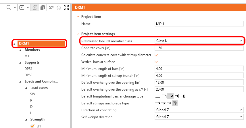
\[ \textsf{\textit{\footnotesize{Fig. 53\qquad Prestressed flexural member class selection}}}\]
La tensión de compresión admisible para elementos sometidos a cargas transitorias está especificada por ACI 318-19 24.5.4.1 como 0.6fc'. El límite de tensión de compresión de 0.45fc' se estableció para reducir la probabilidad de fallo de elementos de hormigón pretensado bajo cargas repetidas. Este límite también pareció razonable para evitar deformaciones excesivas por fluencia. A valores de tensión más elevados, las deformaciones por fluencia tienden a aumentar más rápidamente a medida que aumenta la tensión aplicada.
La tensión del hormigón a compresión se evalúa como la relación entre la tensión principal máxima de compresión fc = σc2 obtenida del análisis por elementos finitos para servicio y el valor límite, que se establece según la Tabla 24.5.4.1.
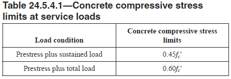
\[ \textsf{\textit{\footnotesize{Fig. 54\qquad Concrete compressive stress limits at service loads}}}\]
En la aplicación, Pretensado más carga sostenida se trata como una combinación a largo plazo, y Pretensado más carga total como una combinación a corto plazo.
Flecha
En función del tipo de combinación seleccionado (largo plazo o corto plazo), se evalúa la flecha a largo plazo o a corto plazo. El valor máximo admisible de flecha deberá ser determinado por el usuario y deberá considerarse de acuerdo con ACI 138-19 24.2.
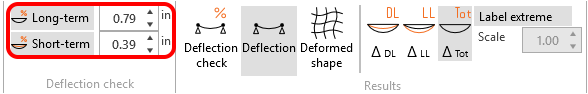
\[ \textsf{\textit{\footnotesize{Fig. 55\qquad Maximum allowable deflection value}}}\]
En la aplicación, es posible mostrar las flechas debidas a la carga permanente ΔDL y a la sobrecarga de uso ΔLL por separado, así como la flecha total ΔTot (permanente+variable), todo ello mostrando la forma deformada.
Las flechas en los extremos recortados no pueden verificarse.
Anchura de fisura
Las anchuras de fisura y las orientaciones de fisura se calculan para combinaciones de servicio a corto plazo o a largo plazo. Dado que ACI no prescribe directamente anchuras de fisura límite, el usuario debe especificar una anchura de fisura límite wlim.
Las verificaciones se presentan de la siguiente manera:
\[\frac{w}{w_{lim}}\]
donde:
w anchura de fisura a corto o largo plazo calculada mediante análisis por elementos finitos,
wlim valor límite de la anchura de fisura definido por el usuario.
El método de cálculo de anchuras de fisura utilizado en la aplicación, descrito también con más detalle en este documento, está de acuerdo con ACI 224R-01. Por tanto, es posible utilizar la Tabla 4.1 de ACI 224R-01 para determinar el valor límite de las anchuras de fisura.
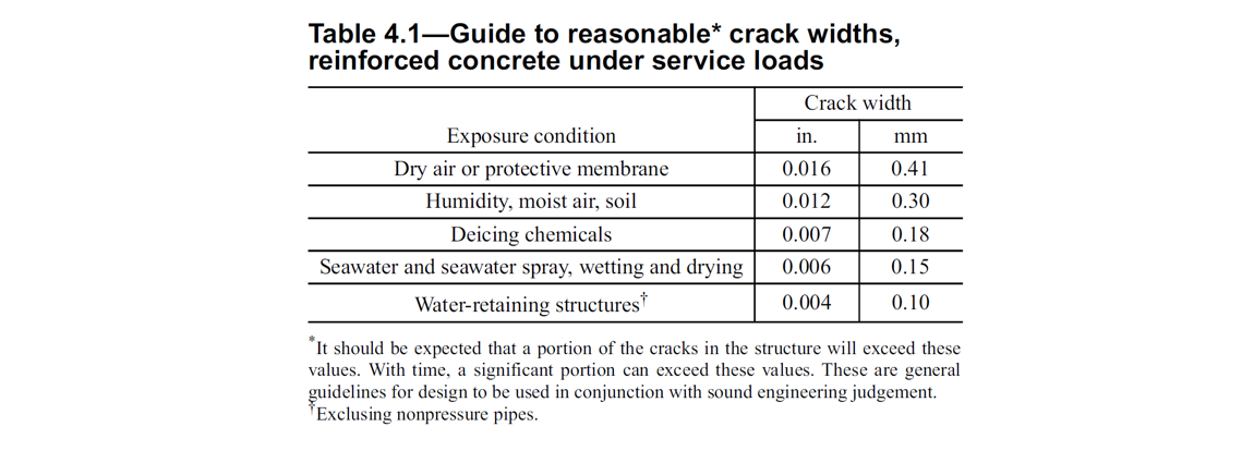
\[ \textsf{\textit{\footnotesize{Fig. 56\qquad Reasonable crack widths for reinforced concrete under service load}}}\]
Existen dos formas de calcular las anchuras de fisura (fisuración estabilizada y no estabilizada). En el caso general (fisuración estabilizada), la anchura de fisura se calcula integrando las deformaciones en los elementos 1D de las barras de armadura. La dirección de la fisura se calcula a partir de los tres puntos de integración más cercanos (al centro del elemento finito 1D de armadura dado) de los elementos 2D de hormigón. Aunque este enfoque para calcular las direcciones de fisura no se corresponde con la posición real de las fisuras, proporciona valores representativos que conducen a resultados de anchura de fisura comparables con los valores de anchura de fisura requeridos por la normativa en la posición de la barra de armadura.
6 Verificaciones estructurales según AASHTO
6.1 Modelos de material (AASHTO)
Hormigón - Resistencia
El modelo de hormigón implementado para los cálculos de resistencia en CSFM se basa en las hipótesis de diseño por resistencia de AASHTO LRFD de equilibrio y compatibilidad de deformaciones. De acuerdo con el Artículo 5.6.2.1 de AASHTO LRFD (2024), se desprecia la resistencia a tracción del hormigón.
\[ \textsf{\textit{\footnotesize{Fig. 57\qquad The stress-strain diagram of concrete for Strength analysis}}}\]
La implementación del CSFM en IDEA StatiCa Detail no considera un criterio de fallo explícito en términos de deformaciones para el hormigón en compresión (es decir, tras alcanzar la tensión máxima, considera una rama plástica con εc0 con un valor máximo del 5%, mientras que el Artículo 5.6.2.1 de AASHTO LRFD (2024) asume una deformación última inferior al 0,3%). Esta simplificación no permite verificar la capacidad de deformación de las estructuras que fallan a compresión. Sin embargo, la resistencia se predice correctamente cuando, además del factor de hormigón fisurado (kc2 definido en la Fig. 57), se considera el aumento de la fragilidad del hormigón a medida que aumenta su resistencia mediante el factor de reducción \(\eta_{fc}\) definido en el fib Model Code 2010 de la siguiente manera:
\[f'_{c,lim}=\alpha_{1}\cdot\phi_{c}\cdot k_{c}\cdot f'_{c}\]
\[k_{c}=\eta_{fc}\cdot k_{c2}\]
\[{\eta _{fc}} = {\left( {\frac{{30}}{{{f'_{c}}}}} \right)^{\frac{1}{3}}} \le 1\]
donde:
α1 es el factor de reducción de la resistencia a compresión del hormigón definido en el Artículo 5.6.2.2 de AASHTO LRFD (2024). Al utilizar un diagrama tensión-deformación parábola-rectángulo, es necesario reducir la tensión máxima de compresión mediante este factor. Esto promedia la distribución de tensiones en la zona comprimida de tal manera que la resistencia a compresión resultante es menor o igual a la resistencia a compresión calculada mediante un diagrama tensión-deformación con una rama plástica decreciente.
Φc es el factor de resistencia del hormigón. El valor por defecto se establece según el Artículo 5.5.4.2 de AASHTO LRFD (2024).
kc2 es el factor de reducción debido a la presencia de fisuración transversal.
f'c es la resistencia a compresión del hormigón en probeta cilíndrica (en MPa para la definición de \( \eta_{fc} \)).
\[ \textsf{\textit{\footnotesize{Fig. 58\qquad The compression softening law.}}}\]
kc2 es un factor de reducción basado en las mismas hipótesis que el factor de eficiencia del hormigón ν indicado en AASHTO LRFD (2024) 5.8.2.5.3a y la Tabla 5.8.2.5.3a-1, excepto que en CSFM, la presencia de una tensión principal de tracción perpendicular a la tensión principal de compresión se comprueba para cada elemento finito (no solo para los nodos del modelo Biela y tirante).
Hormigón – Estado límite de servicio
El análisis en estado límite de servicio contiene ciertas simplificaciones de los modelos constitutivos utilizados para el análisis de resistencia. Se desprecia la rama plástica del diagrama tensión-deformación del hormigón en compresión, mientras que la rama elástica es lineal e ilimitada. No se considera la ley de ablandamiento a compresión. Estas simplificaciones mejoran la estabilidad numérica y la velocidad de cálculo, y no reducen la generalidad de la solución siempre que los límites de tensión resultantes en los materiales en servicio estén claramente por debajo de sus puntos de plastificación (coherente con el enfoque del estado límite de servicio de AASHTO LRFD). Por tanto, los modelos simplificados utilizados para el estado límite de servicio solo son válidos si se cumplen todos los requisitos de verificación.

\[ \textsf{\textit{\footnotesize{Fig. 59\qquad Concrete stress-strain diagrams implemented for serviceability analysis: short- and long-term verifications.}}}\]
Efectos a largo plazo
La ley constitutiva a largo plazo (la curva roja de la Fig. 59) se utiliza para el cálculo de la abertura de fisura, la flecha total y la limitación de tensiones en elementos pretensados cuando se selecciona el efecto a largo plazo en la barra superior. En la aplicación Detail de IDEA StatiCa, se utiliza el módulo de elasticidad efectivo para la verificación de efectos a largo plazo, tal como se menciona en AASHTO LRFD (2024) C5.12.5.3.6-1.
\[E_{eff} = \frac{E_{c}}{1+\psi}\]
donde:
Ec es el módulo de elasticidad definido en el Artículo 5.4.2.4 de AASHTO LRFD (2024)
ψ es el coeficiente de fluencia definido en el Artículo 5.4.2.3.2 de AASHTO LRFD (2024)
Los factores de fluencia son definidos por el usuario en las propiedades del material.
Efectos a corto plazo
Para realizar las verificaciones a corto plazo, se lleva a cabo otro cálculo en el que todas las cargas se calculan sin el factor de fluencia. Ambos cálculos para las verificaciones a largo y corto plazo se representan en la Fig. 59.
Armadura
Se considera un diagrama tensión-deformación perfectamente elastoplástico con un límite elástico definido para la armadura no pretensada, véase el Artículo 5.4.3 de AASHTO LRFD (2024). La definición de este diagrama solo requiere conocer las propiedades básicas de la armadura: la resistencia y el módulo de elasticidad.
El diagrama tensión-deformación de la armadura también puede ser definido por el usuario, pero en este caso no es posible considerar el efecto de rigidización a tracción (no es posible calcular la abertura de fisura).
\[ \textsf{\textit{\footnotesize{Fig. 60 \qquad Stress-strain diagram of reinforcement}}}\]
donde:
Φs es el factor de resistencia de la armadura. El valor por defecto se establece según el Artículo 5.5.4.2 de AASHTO LRFD (2024).
fy es la resistencia a la fluencia de la armadura
Es módulo de elasticidad de la armadura
Se selecciona el 10% como deformación límite a la que se detiene el cálculo. Esto se considera seguro según el Artículo 7 de ASTM A955/A955M-20c.
La rigidización a tracción (Fig. 61) se tiene en cuenta automáticamente modificando la relación tensión-deformación de entrada de la barra de armadura desnuda con el fin de capturar la rigidez media de las barras embebidas en el hormigón (εm).
\[ \textsf{\textit{\footnotesize{Fig. 61\qquad Scheme of tension stiffening.}}}\]
6.2 Factores de resistencia y de carga
El Método del Campo de Tensiones Compatible cumple con los códigos de diseño modernos. Como los modelos de cálculo solo utilizan propiedades de los materiales estándar, el formato de coeficientes de seguridad parciales prescrito en los códigos de diseño puede aplicarse sin ninguna adaptación. De este modo, las cargas de entrada se mayoradas y las propiedades características de los materiales se reducen mediante los correspondientes factores de resistencia, exactamente igual que en el análisis convencional del hormigón.
Los valores de los factores de resistencia están prescritos en AASHTO LRFD (2024), Artículo 5.5.4. Los valores por defecto para el hormigón y la armadura se eligen de forma conservadora, basándose en la suposición de que el ejemplo resuelto típico es una región D, un caso habitual para el método Biela-y-tirante. Sin embargo, es posible modelar cualquier tipo de elemento. Por tanto, si se evalúa un elemento controlado por compresión o tracción, el usuario tiene la opción de modificar el valor del factor de reducción de resistencia en las Preferencias.

\[ \textsf{\textit{\footnotesize{Fig. 62\qquad The setting of resistance factors in IDEA StatiCa Detail.}}}\]
Los factores de carga y las combinaciones de carga deberán definirse de acuerdo con las Especificaciones de Diseño de Puentes AASHTO LRFD (2024), Artículo 3.4.1 y Tablas 3.4.1-1 a 3.4.1-6. AASHTO LRFD especifica explícitamente las combinaciones de carga en estado límite de resistencia (Resistencia I a Resistencia V), así como las combinaciones de carga en nivel de servicio (Servicio I a Servicio IV), incluidos los correspondientes factores de carga para cada caso.
Para cada plantilla, el programa incluye combinaciones básicas predefinidas que requieren completarse en función del elemento que se esté procesando.

\[ \textsf{\textit{\footnotesize{Fig. 63\qquad The setting of load factors in Idea StatiCa Detail.}}}\]
6.3 Estado límite de resistencia
Las diferentes verificaciones requeridas por AASHTO se evalúan a partir de los resultados directos proporcionados por el modelo. Las verificaciones se realizan para la resistencia del hormigón, la resistencia de la armadura y el anclaje (tensiones tangenciales de adherencia).
La resistencia del hormigón a compresión se evalúa como la relación entre la tensión principal máxima de compresión fc (también σ2 en los resultados auxiliares) obtenida del análisis de elementos finitos y el valor límite f'c,lim.
La resistencia de la armadura se evalúa tanto a tracción como a compresión como la relación entre la tensión en la armadura en las fisuras fs y el valor límite especificado fy,lim.
La tensión tangencial de adherencia se evalúa de forma independiente como la relación entre la tensión de adherencia τb calculada mediante el análisis de elementos finitos y la resistencia de adherencia fbu.
Sin embargo, dado que la resistencia de adherencia no está definida explícitamente en AASHTO, su valor debe determinarse mediante las ecuaciones que definen la longitud de desarrollo. La resistencia de adherencia es, de hecho, el parámetro de entrada principal para determinar la longitud de desarrollo; véase, por ejemplo, el artículo AASHTO LRFD (2024) C5.10.8.2 o el Informe NCHRP 733, Anexo E, página E-9.
El cálculo descrito en los artículos 5.10.8.2.1 y 5.10.8.2.2 de AASHTO LRFD (2024), que requiere conocer la separación máxima entre ejes de la armadura transversal dentro de ld, el número de barras o alambres desarrollados a lo largo del plano de fisuración, el área total de la sección transversal de toda la armadura transversal y otras magnitudes geométricas que no pueden determinarse de forma fiable en el modelo de la aplicación Detail para una entrada general, se adoptó un enfoque del artículo 5.11.2.1.1 de AASHTO LRFD (2014) de la siguiente manera:
Supongamos que si anclamos la barra de armadura en un bloque de hormigón hasta la longitud de desarrollo ld o mayor, el arranque de la armadura conducirá a la rotura de la armadura y no al arrancamiento del hormigón. Esto puede expresarse con la siguiente fórmula.
\[\pi\cdot d_{b} \cdot l_{d} \cdot f_{bu}=f_{y}\cdot A_{b}\]
donde:
- db es el diámetro de la barra de armadura
- ld es la longitud de desarrollo
- fbu es la resistencia de adherencia
- fy es el límite elástico de la armadura
- Ab es el área de la barra de armadura
A partir de lo anterior, la fórmula para calcular la resistencia de adherencia puede derivarse fácilmente.
\[f_{bu}=\frac{f_{y}\cdot A_{b}}{\pi\cdot d_{b} \cdot l_{d} }\]
La longitud de desarrollo básica a tracción ldb se determina en el artículo 5.11.2.1.1 de AASHTO LRFD (2014) de la siguiente manera:
Para barras del No. 11 e inferiores: \(l_{bd}=\max\left(1.25\cdot\dfrac{A_{b}\cdot f_{y}}{\sqrt{f'_{c}}},\ 0.4\cdot d_{b}\cdot f_{y}\right)\)
Para barras del No. 14: \(l_{bd}=\dfrac{2.70\cdot f_{y}}{\sqrt{f'_{c}}}\)
Para barras del No. 18: \(l_{bd}=\dfrac{3.5\cdot f_{y}}{\sqrt{f'_{c}}}\)
donde:
- Ab es el área de la barra de armadura (in2)
- fy es el límite elástico especificado de la armadura (ksi)
- f'c resistencia a compresión especificada del hormigón a 28 días, salvo que se especifique otra edad (ksi)
- db es el diámetro de la barra de armadura (in)
A continuación, multiplicando la longitud de desarrollo básica ldb por los factores descritos en los artículos 5.11.2.1.2 y 5.11.2.1.3 de AASHTO LRFD (2014), se determina la longitud de desarrollo ld como dato de entrada.
Los factores de modificación que reducen la longitud de desarrollo del artículo 5.11.2.1.3 son siempre iguales a 1,0 en la aplicación. El factor de modificación para la armadura horizontal superior o casi horizontal es igual a 1,4 para condiciones de adherencia «deficientes», según la figura siguiente:

\[ \textsf{\textit{\footnotesize{Fig. 64\qquad Description of bond conditions; a) b) 'good' bond conditions for all bars; c) d) unhatched zone – 'good' bond conditions, hatched zone – 'poor' bond conditions}}}\]
La dirección del hormigonado puede establecerse en la aplicación.
\[ \textsf{\textit{\footnotesize{Fig. 65\qquad Direction of concreting}}}\]
Todos los demás factores determinados en el artículo 5.11.2.1.2 son iguales a 1,0 porque solo se admite hormigón de peso normal y únicamente armadura sin revestimiento.
La tensión tangencial de adherencia y la resistencia de adherencia de las barras a compresión se calculan de forma análoga a las barras a tracción, pero se utilizan las ecuaciones del artículo 5.11.2.2 de AASHTO LRFD (2014).
También existe la opción de modelar barras lisas. Puede encontrarse más información aquí: Barras lisas en Detail
Fuerza total Ftot y fuerza límite Flim
La fuerza total Ftot es un resultado del análisis de elementos finitos y puede definirse de dos maneras.
\[F_{tot}=A_{b} \cdot f_{s}\]
donde Ab es el área de la barra de armadura y fs es la tensión en la barra.
O como suma de la fuerza de anclaje Fa y la fuerza de adherencia Fbond.
\[F_{tot}=F_{a}+F_{bond}\]
donde Fa es la fuerza real en el muelle de anclaje y Fbond es la fuerza de adherencia que puede obtenerse integrando la tensión de adherencia τb a lo largo de la longitud de la barra de armadura l.
\[F_{bond}=C_{s} \cdot \int_{0}^{l}\tau_{b}\left( x \right)dx\]
Cs es el perímetro de la barra de armadura.
La fuerza límite Flim es la fuerza máxima en el elemento de la barra considerando la resistencia de la barra y también las condiciones de anclaje (adherencia entre el hormigón y la armadura y ganchos de anclaje, lazos, etc.).
\[F_{lim}=min\left( F_{lim,bond}+F_{au},F_{u} \right)\]
\[F_{u}=f_{y,lim}\cdot A_{b}\]
\[F_{au}=\beta\cdot f_{y,lim}\cdot A_{b}\]
\[F_{lim,bond}=C_{s}\cdot l \cdot f_{bu}\]
donde Cs es el perímetro de la barra de armadura y l es la longitud desde el inicio de la barra hasta el punto de interés.
\[ \textsf{\textit{\footnotesize{Fig. 66\qquad Definition of the limit force Flim}}}\]
\[F_{lim,2}=F_{lim,1}+F_{lim,add}\]
donde Flim,add es la fuerza adicional calculada a partir de la magnitud del ángulo entre elementos adyacentes. Flim,2 debe ser siempre inferior a Fu.
Los tipos de anclaje disponibles en CSFM incluyen barra recta (es decir, sin reducción en el extremo de anclaje), gancho a 90 grados, gancho a 180 grados, adherencia perfecta y barra continua. Todos estos tipos, junto con los coeficientes de anclaje β respectivos, se muestran en la Fig. 67 para la armadura longitudinal. Los valores de los coeficientes de anclaje adoptados se derivan de la comparación de la ecuación del apartado 5.11.2.1 de AASHTO LRFD (2014) y las ecuaciones tomadas del apartado 5.11.2.4.1 de AASHTO LRFD (2014). Cabe señalar que, a pesar de las diferentes opciones disponibles, CSFM distingue tres tipos de extremos de anclaje: (i) sin reducción en la longitud de anclaje, (ii) una reducción del 30% de la longitud de anclaje en el caso de un anclaje normalizado, y (iii) adherencia perfecta.
\[ \textsf{\textit{\footnotesize{Fig. 67\qquad Available anchorage types and respective anchorage coefficients for longitudinal reinforcing bars in CSFM:}}}\]
\[ \textsf{\textit{\footnotesize{(a) straight bar; (b) 90-degree hook; (c) 180-degree hook; (d) perfect bond; (e) continuous bar}}}\]
El coeficiente de anclaje para estribos (disponible para el elemento Beam) es siempre β = 1,0.
Para cumplir con AASHTO, el muelle de anclaje debe utilizarse en el cálculo. El muelle de anclaje se modifica mediante el coeficiente β, por lo que el usuario debe utilizar uno de los tipos de anclaje disponibles al definir las condiciones de inicio y fin de la armadura.
6.4 Resistencia de zonas de apoyo y anclaje – Áreas parcialmente cargadas
Al diseñar estructuras de hormigón, nos encontramos con dos grandes grupos de áreas parcialmente cargadas (APC): el primero comprende los apoyos, mientras que el otro está formado por las zonas de anclaje.
De acuerdo con las normas actualmente vigentes para el diseño de estructuras de hormigón armado, deben considerarse el aplastamiento local del hormigón y las fuerzas de tracción transversal para los apoyos. Para una carga uniformemente distribuida sobre un área, A1, la capacidad a compresión del hormigón puede incrementarse hasta dos veces en función del área de distribución de cálculo A2. Véase el artículo 5.6.5 de AASHTO LRFD (2024).

\[ \textsf{\textit{\footnotesize{Fig. 68\qquad Partially loaded areas for bearings according to AASHTO LRFD (2024) Article 5.6.5}}}\]
Para las zonas de anclaje postensadas, debe seguirse el artículo 5.8.4.4 de AASHTO LRFD (2024).
El área parcialmente cargada debe estar suficientemente armada con armadura transversal diseñada para transmitir las fuerzas de fisuración que se producen en la zona. Sin la armadura transversal requerida, no es posible considerar el incremento de la capacidad a compresión del hormigón.
Áreas parcialmente cargadas en CSFM
\[ \textsf{\textit{\footnotesize{Fig. 69\qquad Fictitious struts with concrete finite element mesh.}}}\]
Mediante CSFM, es posible diseñar y verificar estructuras de hormigón armado incluyendo la influencia del incremento de la resistencia a compresión del hormigón en áreas parcialmente cargadas. Dado que CSFM es un modelo de lámina (2D) y las áreas parcialmente cargadas son una tarea espacial (3D), fue necesario encontrar una solución que combinara estos dos tipos de tareas diferentes (Fig. 69). Si se activa la función "áreas parcialmente cargadas", la geometría del cono admisible se crea según ACI (Fig. 68). Todas las colisiones geométricas se resuelven completamente en 3D para la geometría del elemento de hormigón especificada y las dimensiones de cada APC. Posteriormente, se crea un modelo de cálculo del área parcialmente cargada.
\[ \textsf{\textit{\footnotesize{Fig. 70\qquad Allowable cone geometries.}}}\]
La modificación del modelo de material resultó ser un enfoque inadecuado, principalmente porque la asignación de propiedades a la malla de elementos finitos es problemática. Se determinó que un enfoque independiente de la malla de elementos finitos es una solución más apropiada. Se crean bielas ficticias absolutamente coherentes para la geometría conocida del cono de compresión (Fig. 70 y Fig. 71). Estas bielas tienen propiedades de material idénticas al hormigón utilizado en el modelo, incluido el diagrama tensión-deformación. La forma del cono determina la dirección de las bielas, que distribuye gradualmente la carga sobre el APC hacia el área de distribución de cálculo. La densidad superficial de las bielas ficticias es variable en cada parte del cono y añade un área ficticia de hormigón en la dirección de la carga. Al nivel del área cargada (A1), se añade un área ficticia de hormigón según la relación \(\sqrt{A_{1} \cdot A_{2}} - A_{real}\) (donde Areal es el área del apoyo considerada en el modelo de cálculo 2D), y esta área disminuye linealmente hasta cero hacia el área de distribución de cálculo (A2). Esta solución garantiza que la tensión de compresión en el hormigón sea constante en todo el volumen del cono.
\[\rho \left( {\beta ,z} \right) = \left( {\sqrt {\frac{A_{2}}{A_{1}}} - \frac{A_{real}}{A_{1}}} \right)\,\cdot\,\left( {1 - \frac{z}{h}} \right)\,\cdot\,\frac{1}{{\cos \beta }}\]
\[ \textsf{\textit{\footnotesize{Fig. 71\qquad Fictitious struts in the computational model}}}\]
La resistencia del área parcialmente cargada se incrementa según la relación entre el área de distribución de cálculo y el área cargada establecida en el artículo 5.6.5 de AASHTO LRFD (2024). Debe recordarse que se trata de un modelo de cálculo que no puede describir con precisión el estado tensional en un área parcialmente cargada, cuyo flujo real es mucho más complejo. Sin embargo, esta solución permite la distribución correcta de la carga en todo el modelo respetando la mayor capacidad de carga del área parcialmente cargada. Además, introduce correctamente las tensiones transversales en esta zona para diseñar correctamente la armadura frente a las fuerzas de fisuración.
La tensión admisible de apoyo de 0,85fc' se recoge en el artículo 5.8.4.4 de AASHTO LRFD (2024). La densidad está limitada de modo que no se supere la capacidad doble máxima indicada en la fórmula 5.6.5-3.
Para las zonas de anclaje, el APC se utiliza de la misma manera que para los apoyos en la aplicación. Por ello, las tensiones de compresión en las zonas local y global definidas en los artículos 5.8.4.4 y 5.8.4.5 deben verificarse manualmente. El APC se utiliza, por tanto, únicamente para evitar superar el criterio de deformación en la zona local y así detener prematuramente el cálculo. Por otro lado, la armadura que resiste las tensiones de fisuración, descascarillado en el plano y tracción en el borde en las zonas generales (definidas en el artículo 5.8.4.5) puede verificarse directa y ventajosamente en la aplicación.
6.5 Estado límite de servicio
Las verificaciones de servicio se realizan para la limitación de tensiones, la anchura de fisura y los límites de flecha. Las tensiones se verifican en los elementos de hormigón y armadura según AASHTO LRFD de manera similar a la especificada para el Estado Resistente.
Limitación de tensiones
La tensión de compresión en el hormigón se evalúa únicamente para elementos pretensados (cuando el caso de carga de Pretensado está presente en el modelo) como la relación entre la tensión principal máxima de compresión fc = σc2 obtenida del análisis de elementos finitos para servicio y los valores límite, que se establecen según la Tabla 5.9.2.3.2a-1 de AASHTO LRFD.

\[ \textsf{\textit{\footnotesize{Fig. 72\qquad Concrete compressive stress limits at service loads}}}\]
En la aplicación, Pretensado más carga permanente se trata como carga sostenida, y Pretensado, carga permanente y transitoria como carga total.

\[ \textsf{\textit{\footnotesize{Fig. 73\qquad Serviceability combination types}}}\]
Además, siempre es posible realizar un análisis tanto para efectos a corto plazo como a largo plazo, utilizando modelos de material que tengan en cuenta o no el factor de fluencia; véase la sección "Modelos de material (AASHTO)".

\[ \textsf{\textit{\footnotesize{Fig. 74\qquad Serviceability material models}}}\]
Flecha
Las flechas instantáneas y las flechas totales se evalúan para cada combinación en la que la evaluación de flechas está habilitada.
- Para las flechas instantáneas, se utiliza el módulo de elasticidad Ec según el artículo 5.4.2.4 de AASHTO LRFD (2024).
- Para las flechas totales, se utiliza el módulo de elasticidad efectivo Ec,eff según el artículo C5.12.5.3.6 de AASHTO LRFD (2024).
Véase el capítulo 'Modelos de material (AASHTO) - Hormigón – Servicio' en este documento.
La verificación de la flecha se habilita en la barra de herramientas superior. El usuario establece los valores límite de flecha según el artículo 2.5.2.6.2 de AASHTO LRFD (2024), en función del tipo de elemento analizado.

\[ \textsf{\textit{\footnotesize{Fig. 75\qquad Maximum allowable deflection value}}}\]
Las flechas en los extremos recortados no pueden verificarse.
Anchura de fisura
Las anchuras y orientaciones de fisura se calculan únicamente para efectos a largo plazo (utilizando Ec,eff según el artículo C5.12.5.3.6 de AASHTO LRFD (2024)) para las combinaciones en las que la evaluación de la anchura de fisura está habilitada. Las verificaciones basadas en los valores límite definidos por el usuario son las siguientes:
\[\frac{w}{w_{lim}}\]
donde:
w anchura de fisura calculada mediante análisis de elementos finitos,
wlim valor límite de la anchura de fisura definido por el usuario.
El valor límite wlim deberá determinarse en función del tipo de elemento y la clase de exposición de acuerdo con el artículo 5.6.7 de AASHTO LRFD (2024) y su comentario.
Existen dos formas de calcular las anchuras de fisura (fisuración estabilizada y no estabilizada). En el caso general (fisuración estabilizada), la anchura de fisura se calcula integrando las deformaciones en los elementos 1D de las barras de armadura. La dirección de la fisura se calcula a partir de los tres puntos de integración más cercanos (al centro del elemento finito 1D de armadura dado) de los elementos 2D de hormigón. Aunque este enfoque para calcular las direcciones de fisura no corresponde a la posición real de las fisuras, proporciona valores representativos que conducen a resultados de anchura de fisura comparables con los valores de anchura de fisura requeridos por la normativa en la posición de la barra de armadura.
7 Verificaciones estructurales según la norma australiana AS 3600 (2018)
La evaluación de la estructura mediante CSFM se realiza mediante dos análisis diferentes: uno para las combinaciones de carga en servicio y otro para las combinaciones de carga de resistencia. El análisis en servicio asume que el comportamiento bajo cargas mayoradas es satisfactorio y que las condiciones de plastificación del material no se alcanzarán en los niveles de carga de servicio. Este enfoque permite el uso de modelos constitutivos simplificados (con una rama lineal del diagrama tensión-deformación del hormigón) para el análisis en servicio, con el fin de mejorar la estabilidad numérica y la velocidad de cálculo.
El CSFM es un método de análisis estructural que satisface las reglas generales de los apartados 6.1.1 y 6.1.2 y se define como (f) análisis de tensiones no lineal en el apartado 6.1.3, desarrollado posteriormente en el apartado 6.6.
El análisis mediante CSFM tiene en cuenta todos los efectos no lineales e inelásticos relevantes (excepto la retracción) definidos en el apartado 6.6.3.
Para satisfacer los requisitos de los apartados 6.6.4 y 6.6.5 —puede consultarse más información en AS3600:2018 Sup 1:2022, apartado C6.6—, se realizaron verificaciones y validaciones del método en diversas universidades. Los artículos individuales que resumen los resultados de verificación y validación pueden consultarse en el siguiente enlace.
Dado que IDEA StatiCa Detail es un programa de diseño práctico, para los cálculos se utiliza la resistencia característica mayorada a compresión en cilindro a 28 días f'c, tal como se describe en el capítulo siguiente.
7.1 Modelos de material (AS 3600)
Hormigón - Resistencia
El modelo de hormigón implementado para los cálculos de resistencia en CSFM se basa en la curva tensión-deformación parabólica-plástica. La resistencia a tracción se desprecia, como ocurre en el diseño clásico de hormigón armado.
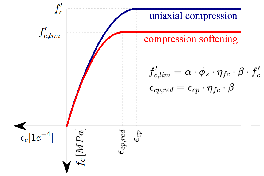
\[ \textsf{\textit{\footnotesize{Fig. 76\qquad The stress-strain diagram of concrete for Strength analysis}}}\]
La implementación del CSFM en IDEA StatiCa Detail no considera un criterio de fallo explícito en términos de deformaciones para el hormigón en compresión (es decir, una vez alcanzada la tensión máxima, considera una rama plástica con εc0 con un valor máximo del 5%, mientras que AS 3600 Cl. 8.3.1 asume una deformación última inferior al 0,3%). Esta simplificación no permite verificar la capacidad de deformación de las estructuras que fallan a compresión. Sin embargo, la resistencia se predice correctamente cuando, además del factor de hormigón fisurado (kc2 definido en la Fig. 77), se considera el aumento de la fragilidad del hormigón a medida que aumenta su resistencia mediante el factor de reducción \(\eta_{fc}\) definido en el fib Model Code 2010 de la siguiente manera:
\[f'_{c,lim}=\alpha_{2}\cdot\phi_{s}\cdot \beta \cdot \eta_{fc}\cdot f'_{c}\]
\[{\eta _{fc}} = {\left( {\frac{{30}}{{{f'_{c}}}}} \right)^{\frac{1}{3}}} \le 1\]
donde:
α2 es el factor de reducción de la resistencia a compresión del hormigón definido en AS 3600 Cl. 8.3.1
Al utilizar un diagrama tensión-deformación parábola-rectángulo, es necesario reducir la tensión máxima de compresión mediante este factor. Esto promedia la distribución de tensiones en la zona comprimida de tal manera que la resistencia a compresión resultante es menor o igual a la resistencia a compresión calculada mediante un diagrama tensión-deformación con una rama plástica decreciente. Un enfoque análogo se define para el bloque rectangular de tensiones en el Capítulo 8.1.3.
Φs es el factor de reducción de tensión para el hormigón. El valor por defecto se establece según AS 3600 Tabla 2.2.3.
β es el factor de reducción debido a la presencia de fisuración transversal (también denominado kc2 en este texto)
f'c es la resistencia del hormigón en probeta cilíndrica (en MPa para la definición de \( \eta_{fc} \)).
\[ \textsf{\textit{\footnotesize{Fig. 77\qquad The compression softening law.}}}\]
β es un factor de reducción basado en los mismos principios que el factor de resistencia a compresión efectiva definido en el Capítulo 2.2.3. La bibliografía a partir de la cual se determina este factor puede consultarse (incluido el contexto de la norma AS3600) en AS3600:2018 Sup 1:2022 CL. C2.2.3.
Hormigón – Aptitud al servicio
El análisis de aptitud al servicio contiene ciertas simplificaciones de los modelos constitutivos utilizados para el análisis de resistencia. La rama plástica de la curva tensión-deformación del hormigón en compresión se desprecia, mientras que la rama elástica es lineal e infinita. La ley de ablandamiento a compresión no se considera. Estas simplificaciones mejoran la estabilidad numérica y la velocidad de cálculo, y no reducen la generalidad de la solución siempre que los límites de tensión resultantes en los materiales en estado límite de servicio estén claramente por debajo de sus puntos de plastificación (según lo exigido por AS3600). Por tanto, los modelos simplificados utilizados para la aptitud al servicio solo son válidos si se cumplen todos los requisitos de verificación.
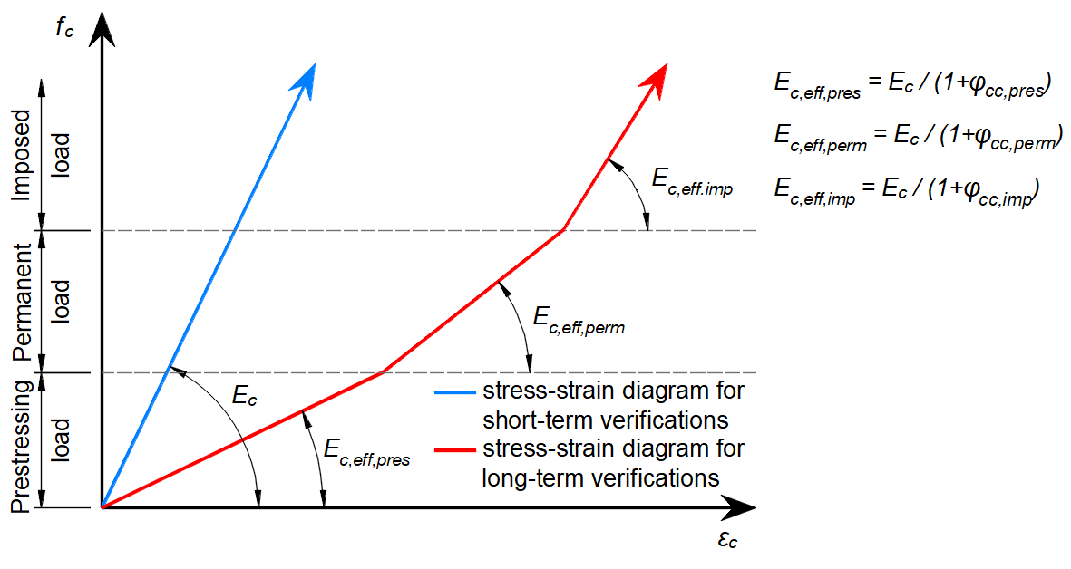
\[ \textsf{\textit{\footnotesize{Fig. 78\qquad Concrete stress-strain diagrams implemented for serviceability analysis: short- and long-term verifications.}}}\]
Efectos a largo plazo
En el análisis de aptitud al servicio, los efectos a largo plazo del hormigón se consideran mediante el coeficiente de fluencia de cálculo según AS 3600 CL 3.1.8 (φcc, tomado con un valor de 2,5 por defecto), que modifica el módulo de elasticidad secante del hormigón (Ec) de la siguiente manera:
\[E_{c,eff} = \frac{E_{c}}{1+\varphi_{cc}}\]
Los incrementos de carga se calculan secuencialmente en el orden: Pretensado - Permanente - Variable, utilizando el módulo de elasticidad efectivo apropiado para cada incremento tal como se muestra en la Fig. 78. Los factores de fluencia son definidos por el usuario en las propiedades del material y deben calcularse según AS 3600 CL 3.1.8.3
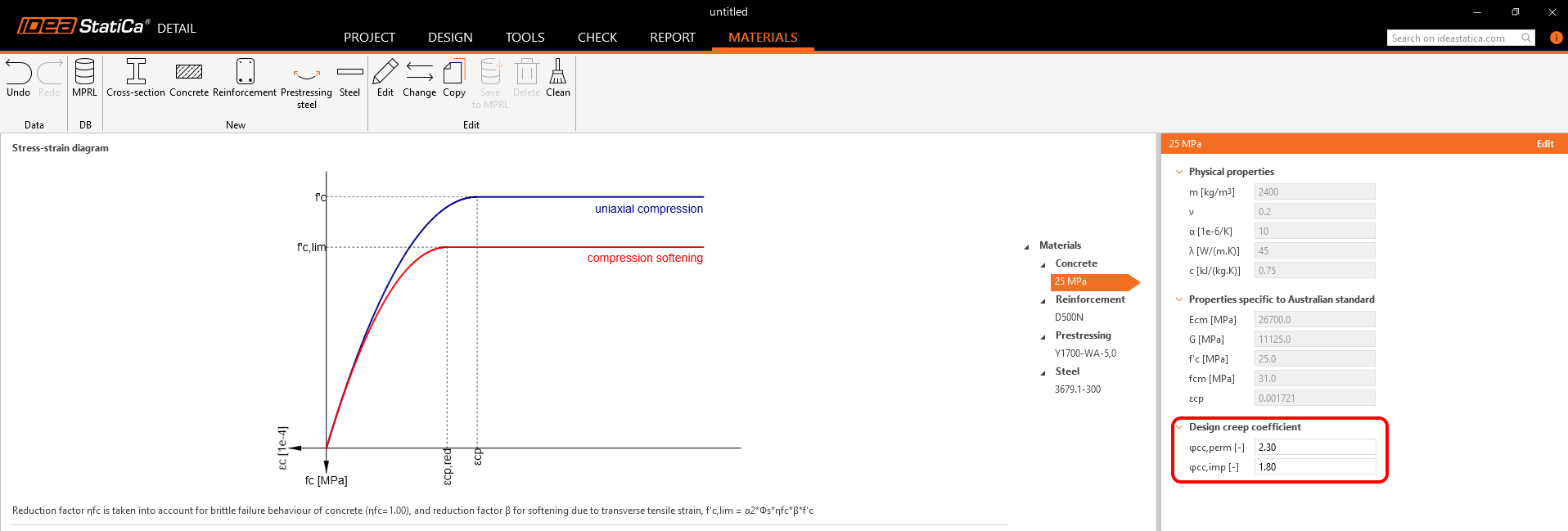
\[ \textsf{\textit{\footnotesize{Fig. 79\qquad Definition of the design creep factor}}}\]
Efectos a corto plazo
Para realizar las verificaciones a corto plazo, se efectúa otro cálculo en el que todas las cargas se calculan sin el factor dependiente del tiempo para las cargas sostenidas. Ambos cálculos para las verificaciones a largo y corto plazo se representan en la Fig. 78.
Armadura
Se considera un diagrama tensión-deformación perfectamente elastoplástico con un límite elástico definido para la armadura no pretensada, véase AS 3600 Sección 3.2. La definición de este diagrama solo requiere conocer las propiedades básicas de la armadura: la resistencia y el módulo de elasticidad.
El diagrama tensión-deformación de la armadura también puede ser definido por el usuario, pero en este caso no es posible considerar el efecto de rigidización a tracción (no es posible calcular la anchura de fisura).
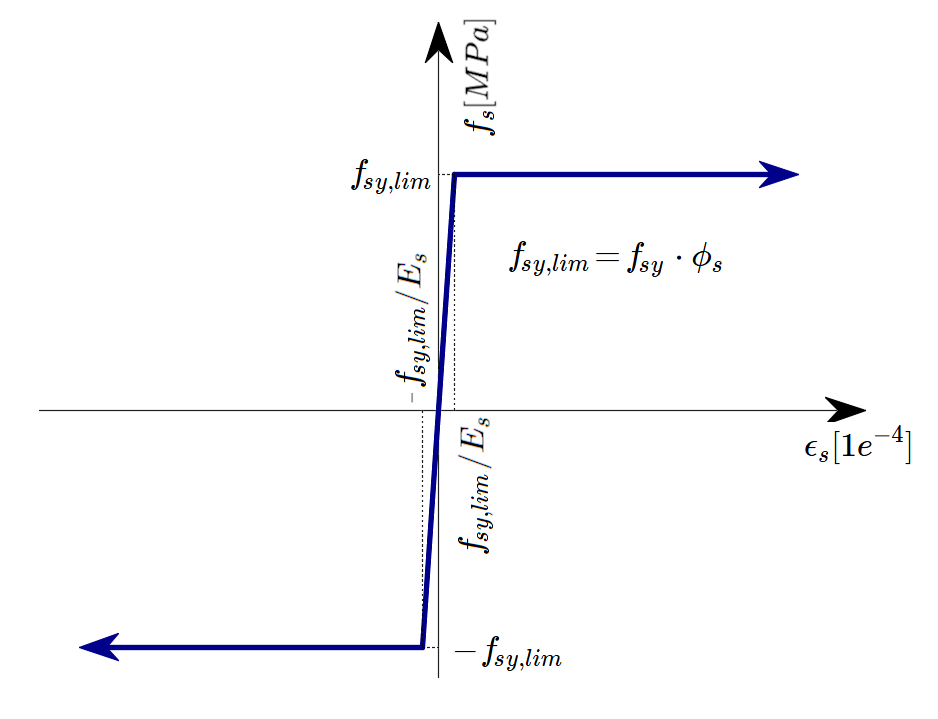
\[ \textsf{\textit{\footnotesize{Fig. 80 \qquad Stress-strain diagram of reinforcement}}}\]
donde:
Φs es el factor de reducción de resistencia para la armadura. El valor por defecto se establece según AS 3600 Tabla 2.2.3.
fy es la resistencia a la fluencia de la armadura
Es módulo de elasticidad de la armadura
La rigidización a tracción (Fig. 81) se tiene en cuenta automáticamente modificando la relación tensión-deformación de entrada de la barra de armadura desnuda con el fin de capturar la rigidez media de las barras embebidas en el hormigón (εm).

\[ \textsf{\textit{\footnotesize{Fig. 81\qquad Scheme of tension stiffening.}}}\]
7.2 Reducción de tensiones y factores de carga
El Método del Campo de Tensiones Compatible cumple con los códigos de diseño modernos. Como los modelos de cálculo solo utilizan propiedades de material estándar, el formato de coeficientes parciales de seguridad prescrito en los códigos de diseño puede aplicarse sin ninguna adaptación. De este modo, las cargas de entrada se mayorан y las propiedades características del material se reducen mediante los respectivos factores de reducción de tensiones, exactamente como en el análisis convencional del hormigón.
Los valores de los factores de reducción de tensiones están prescritos en AUS 3600 Cl. 2.2.3. Los valores por defecto para el hormigón y la armadura se establecen según la Tabla 2.2.3
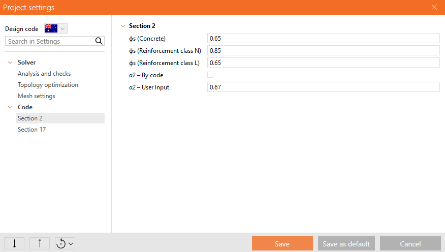
\[ \textsf{\textit{\footnotesize{Fig. 82\qquad The setting of stress reduction factors in IDEA StatiCa Detail.}}}\]
Los factores de carga para combinaciones de Resistencia deberán definirse según AS 3600 Cl. 4.2.2. Los factores de carga para combinaciones de Servicio deberán determinarse según la Tabla 4.1. Para todas las plantillas, los factores de carga ya están predefinidos.
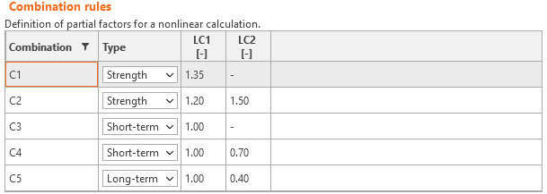
\[ \textsf{\textit{\footnotesize{Fig. 83\qquad The setting of load factors in Idea StatiCa Detail.}}}\]
7.3 Verificaciones de resistencia y longitud de anclaje
Las diferentes verificaciones requeridas por AS 3600 se evalúan a partir de los resultados directos proporcionados por el modelo. Las verificaciones se realizan para la resistencia del hormigón, la resistencia de la armadura y el anclaje (tensiones tangenciales de adherencia).
La resistencia del hormigón a compresión se evalúa como la relación entre la tensión principal máxima de compresión fc (también σ2 en los resultados auxiliares) obtenida del análisis por elementos finitos y el valor límite f'c,lim.
La resistencia de la armadura se evalúa tanto a tracción como a compresión como la relación entre la tensión en la armadura en las fisuras fs y el valor límite especificado fsy,lim.
La tensión tangencial de adherencia se evalúa de forma independiente como la relación entre la tensión de adherencia τb calculada mediante el análisis por elementos finitos y la tensión de adherencia última de cálculo fbu.
Para la determinación de la tensión de adherencia última de cálculo fbu, se considera en la aplicación la fórmula C13.1.2.2 definida en AS3600:2018 Sup 1:2022.
\[f_{bu}=\frac{k_{2}}{k_{1} \cdot k_{3}} \cdot (0.5 \cdot \sqrt{f'_{c}})\]
Donde f'c ≤ 65 MPa (en la fórmula está en MPa), y los factores k se determinan a partir de AS 3600 Cl. 13.1.2.2 de la siguiente manera:
k3 = 0.7 (valor conservador para toda la armadura)
k2 = (132 - db) / 100 (db es el diámetro de la barra en milímetros)
= 1.3 para una barra horizontal con más de 300 mm de hormigón hormigonado por debajo de la barra, o 1.0 en caso contrario
k1 se obtiene automáticamente a partir de la posición de la armadura en el modelo y de la dirección del hormigonado, que puede establecerse en la aplicación para cada elemento del proyecto de la siguiente manera.
\[ \textsf{\textit{\footnotesize{Fig. 84\qquad Direction of concreting}}}\]
La longitud de desarrollo básica Lsy,tb se calcula según la fórmula 13.1.2.2 de AS 3600 de la siguiente manera:
\[L_{sy,tb}=\frac{0.5\cdot k_{1}\cdot k_{3}\cdot f_{sy}\cdot d_{b}}{k_{2}\cdot \sqrt{f'_{c}}}\ge 29 \cdot k_{1}\cdot d_{b}\]
Como puede observarse en la fórmula, la longitud de desarrollo básica Lsy,tb está limitada inferiormente y, por tanto, la tensión de adherencia última de cálculo fbu debe limitarse de la misma manera en la aplicación, por lo que se aplica lo siguiente:
\[f_{bu}\le \frac{f_{sy}}{116 \cdot k_{1}} \]
Donde fsy está en MPa.
La derivación de la limitación de fbu es la siguiente:
\[f_{bu}= \frac{f_{sy}\cdot A_{s}}{ \pi \cdot d_{b} \cdot L_{sy,tb}}=\frac{f_{sy}\cdot \pi \cdot d_{b}^{2}}{4 \cdot \pi \cdot d_{b} \cdot 29 \cdot k{1} \cdot d_{b}} =\frac{f_{sy}}{116 \cdot k_{1}} \]
También existe la opción de modelar barras lisas. Puede encontrarse más información aquí: Barras lisas en Detail
Fuerza total Ftot y fuerza límite Flim
La fuerza total Ftot es un resultado del análisis por elementos finitos y puede definirse de dos maneras.
\[F_{tot}=A_{s} \cdot f_{s}\]
donde As es el área de la barra de armadura y fs es la tensión en la barra.
O como suma de la fuerza de anclaje Fa y la fuerza de adherencia Fbond.
\[F_{tot}=F_{a}+F_{bond}\]
donde Fa es la fuerza real en el muelle de anclaje y Fbond es la fuerza de adherencia que puede obtenerse integrando la tensión de adherencia τb a lo largo de la longitud de la barra de armadura l.
\[F_{bond}=C_{s} \cdot \int_{0}^{l}\tau_{b}\left( x \right)dx\]
Cs es el perímetro de la barra de armadura.
La fuerza límite Flim es la fuerza máxima en el elemento de la barra considerando la resistencia de la barra y también las condiciones de anclaje (adherencia entre el hormigón y la armadura y ganchos de anclaje, lazos, etc.).
\[F_{lim}=min\left( F_{lim,bond}+F_{au},F_{u} \right)\]
\[F_{u}=f_{y,lim}\cdot A_{s}\]
\[F_{au}=\beta\cdot f_{y,lim}\cdot A_{s}\]
\[F_{lim,bond}=C_{s}\cdot l \cdot f_{bu}\]
donde Cs es el perímetro de la barra de armadura y l es la longitud desde el inicio de la barra hasta el punto de interés.
\[ \textsf{\textit{\footnotesize{Fig. 85\qquad Definition of the limit force Flim}}}\]
\[F_{lim,2}=F_{lim,1}+F_{lim,add}\]
donde Flim,add es la fuerza adicional calculada a partir de la magnitud del ángulo entre elementos adyacentes. Flim,2 debe ser siempre inferior a Fu.
Los tipos de anclaje disponibles en CSFM incluyen barra recta (es decir, sin reducción en el extremo de anclaje), patilla normalizada, gancho normalizado, adherencia perfecta y barra continua. Todos estos tipos, junto con los coeficientes de anclaje β respectivos, se muestran en la Fig. 86 para la armadura longitudinal. Los valores de los coeficientes de anclaje adoptados se derivan de AS 3600 Cl. 13.1.2. Cabe señalar que CSFM distingue tres tipos de extremos de anclaje: (i) sin reducción en la longitud de anclaje, (ii) una reducción del 50% de la longitud de anclaje en el caso de un anclaje normalizado, y (iii) adherencia perfecta.

\[ \textsf{\textit{\footnotesize{Fig. 86\qquad Available anchorage types and respective anchorage coefficients for longitudinal reinforcing bars in CSFM:}}}\]
\[ \textsf{\textit{\footnotesize{(a) straight bar; (b) Standard cog; (c) Standard hook; (d) perfect bond; (e) continuous bar}}}\]
El coeficiente de anclaje para los estribos es siempre β = 1.0.
Para cumplir con AS 3600, debe utilizarse el muelle de anclaje en el cálculo; dicho muelle se modifica mediante el coeficiente β, por lo que el usuario debe emplear uno de los tipos de anclaje disponibles al definir las condiciones de inicio y fin de la armadura.
7.4 Verificaciones de estado límite de servicio
Las verificaciones de servicio se llevan a cabo para los límites de ancho de fisura y flecha.
Flecha
En función del tipo de combinación seleccionada (a largo plazo o a corto plazo), se evalúa la flecha a largo plazo o a corto plazo. El valor máximo de flecha admisible deberá ser determinado por el usuario y deberá considerarse de acuerdo con AS 3600 Cl. 2.3.2.
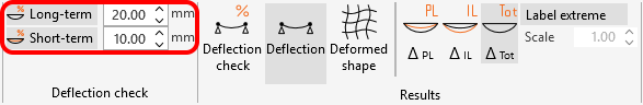
\[ \textsf{\textit{\footnotesize{Fig. 87\qquad Maximum allowable deflection values}}}\]
En la aplicación, es posible mostrar las flechas debidas a la carga permanente ΔPL y a la sobrecarga de uso ΔIL por separado, así como la flecha total ΔTot (permanente + sobrecarga), todo ello mostrando la forma deformada.
Las flechas en los extremos recortados no pueden verificarse.
Ancho de fisura
Los anchos de fisura y las orientaciones de fisura se calculan para combinaciones de servicio a corto plazo o a largo plazo. El método de cálculo directo del ancho de fisura en la aplicación está de acuerdo con (basado en) el método indicado en AS 3600 8.6.2.3.
Las verificaciones se presentan de la siguiente manera:
\[\frac{w}{w_{lim}}\]
donde:
w ancho de fisura a corto o largo plazo calculado mediante análisis por elementos finitos,
wlim valor límite del ancho de fisura definido por el usuario.
Los anchos máximos de fisura recomendados pueden encontrarse en AS3600:2018 Sup 1:2022 Tabla C2.3.3.1.
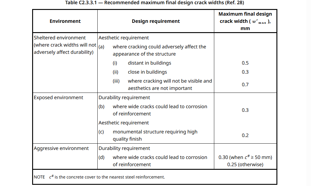
\[ \textsf{\textit{\footnotesize{Fig. 88\qquad Recommended final design crack widths}}}\]
Alternativamente, según AS3600:2018 Sup 1:2022 Cl. C8.6.1 - Para estructuras sometidas a cargas de servicio a largo plazo, los valores recomendados para wlim son los siguientes:
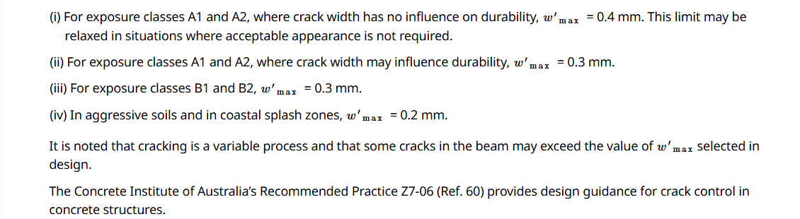
\[ \textsf{\textit{\footnotesize{Fig. 89\qquad Recommended values for the limit value of the crack width for beams based on exposure classes}}}\]
Existen dos formas de calcular los anchos de fisura (fisuración estabilizada y no estabilizada). En el caso general (fisuración estabilizada), el ancho de fisura se calcula integrando las deformaciones en los elementos 1D de las barras de armadura. La dirección de la fisura se calcula a partir de los tres puntos de integración más cercanos (desde el centro del elemento finito 1D de armadura dado) de los elementos 2D de hormigón. Aunque este enfoque para calcular las direcciones de fisura no se corresponde con la posición real de las fisuras, proporciona valores representativos que conducen a resultados de ancho de fisura comparables con los valores de ancho de fisura exigidos por la normativa en la posición de la barra de armadura.
8 Pretensado - descripción del modelo
8 Introducción y modelos de material
El Método del Campo de Tensiones Compatible (CSFM) es un método de cálculo basado en tensiones planas 2D en el que el hormigón se modela mediante elementos finitos 2D a los que se conectan elementos de armadura 1D mediante restricciones. También pueden añadirse al modelo tipos especiales de elementos 1D que representan armadura de pretensado adherida, que puede modelarse como pretensada y postensada.
La armadura de pretensado se modela de forma similar a la armadura convencional mediante elementos lineales que transmiten la fuerza axial. Cada elemento individual de armadura de pretensado se caracteriza por su sección transversal y sus propiedades del material. Estas propiedades vienen dadas por la curva característica del material según la normativa utilizada (EN 1992-1-1, ACI 318-19, etc.)
EUROCÓDIGO
Diagrama tensión-deformación de la armadura de pretensado: a) Diagrama tensión-deformación según EN 1992-1-1; b) deformación inicial para armadura pretensada
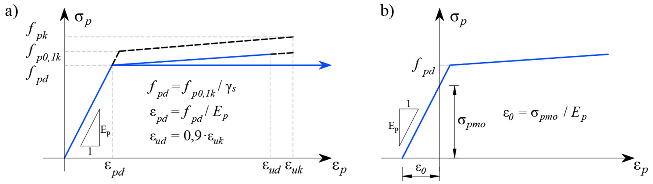
ACI
Diagrama tensión-deformación de la armadura de pretensado: a) Diagrama tensión-deformación; b) deformación inicial para armadura pretensada
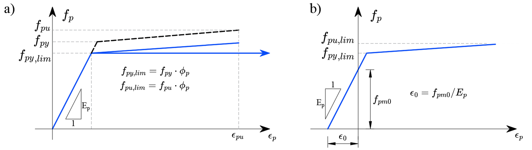
Los elementos de armadura se conectan mediante un modelo de adherencia a los elementos 2D del modelo de hormigón de la misma forma que la armadura convencional de hormigón.
Los elementos del modelo de adherencia permiten la deformación relativa de la armadura de pretensado y el hormigón con características no lineales apropiadas. Esto modela correctamente la cohesión de la armadura con el hormigón y también el modelo de anclaje de la armadura pretensada. Las modificaciones en los extremos de la armadura postensada, por ejemplo, la placa de anclaje, se modelan mediante un elemento con una rigidez correspondiente al anclaje en el extremo de la armadura de pretensado, y la fuerza de pretensado en el extremo se aplica como una carga superficial sobre el modelo de hormigón en un área del tamaño de la placa de anclaje. El modelo no puede describir correctamente la tensión triaxial local en la región sub-anclaje, y esta región debe considerarse por separado.
La rigidización a tracción de la armadura debida a las interacciones con el hormigón no se considera en la armadura de pretensado, ya que se supone que el hormigón en las proximidades de la armadura de pretensado se encuentra en compresión.
Armadura pretensada
La armadura pretensada se tensa antes del hormigonado del elemento; la armadura de pretensado se traza casi siempre en línea recta, por lo que no se producen pérdidas de pretensado por rozamiento. Una vez alcanzada la resistencia del hormigón requerida, la armadura se libera de los bloques de anclaje, activando así la armadura pretensada y transfiriendo las fuerzas de la armadura al hormigón. Este efecto es físicamente equivalente al subenfriamiento de la armadura y se modela mediante una deformación inicial similar a la de la carga térmica. Esto proporciona un diagrama tensión-deformación de la armadura pretensada como se muestra en la figura anterior en b). El modelo de cálculo calcula automáticamente la respuesta deformacional de la estructura al pretensado aplicado y, por tanto, determina directamente las pérdidas de pretensado por deformación elástica del elemento.
Dado que la fuerza de pretensado es conocida, y por tanto también la tensión de pretensado σpmo, el diagrama del material de la armadura se utiliza para la dependencia de la tensión respecto a la deformación y puede escribirse como:
\[{{σ}_{p}}=~{{f}}({{ε}}-{{ε}_{0}})\]
Suponiendo que el pretensado en la armadura es inferior al límite elástico (es decir, se cumplen las condiciones definidas en EN 1992-1-1, apartado 5.10.3), la deformación inicial también puede calcularse como:
\[{{ε}_{0}}=\frac{{{σ}_{pm0}}}{{{E}_{p}}}\]
ε0 - deformación inicial por pretensado
σpm0 - tensión justo antes de la transferencia
Ep - módulo de elasticidad de la armadura de pretensado
La armadura pretensada tiene la particularidad de que su anclaje en los extremos se logra mediante varios mecanismos diferentes: la adhesión de la armadura y el hormigón a nivel molecular, el rozamiento generado en la interfaz entre la superficie de la armadura y el hormigón, el empuje mecánico de la armadura en espiral sobre el hormigón, y el aumento del diámetro de la armadura de pretensado conocido como mecanismo de cuña o efecto Hoyer. Los efectos mencionados se incluyen en el modelo de cálculo CSFM mediante la modificación de las propiedades del modelo de anclaje en la zona extrema de la armadura pretensada.
Interacción de la armadura pretensada y el hormigón: a) armadura en espiral empujando sobre el hormigón; b) efecto Hoyer
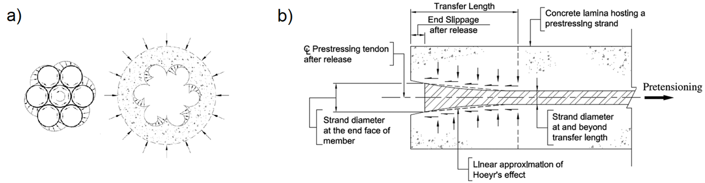
Armadura postensada
La armadura postensada se tensa después de que la estructura ha sido hormigonada. El dispositivo de tesado se apoya directamente en la estructura, eliminando así las pérdidas debidas a la deformación elástica de la estructura por el pretensado. Una vez alcanzada la fuerza de pretensado deseada, la armadura se ancla y, a continuación, se inyectan las vainas de los cables, logrando así la adherencia de la armadura con la estructura. Al modelar la armadura postensada, el cálculo se divide por tanto en varias etapas de carga: pretensado, aplicación de otras cargas permanentes y aplicación de cargas variables.
Malla de elementos finitos de hormigón con elementos 1D de armadura de pretensado conectados:
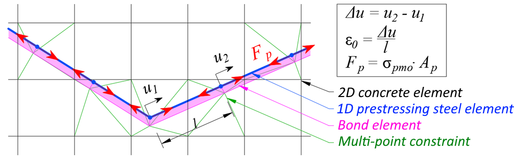
Etapa de carga "pretensado"
Al tensar la armadura, la rigidez de la armadura no se incorpora a la rigidez de la estructura. En esta etapa de carga, la rigidez del elemento lineal no se considera en el modelo; los elementos de armadura se sustituyen por una carga equivalente correspondiente a la tensión de pretensado y el área de la armadura, como se muestra en la figura anterior. Tras alcanzar la carga total del pretensado y la convergencia de esta etapa de carga, se lee la deformación del elemento lineal específico; a partir de la deformación se determina la deformación inicial ε0 de los elementos lineales individuales de la armadura de pretensado.
La tensión de pretensado puede definirse manualmente a lo largo de la longitud de la armadura o calcularse automáticamente en función de la geometría de la armadura. Si se elige el cálculo automático de pérdidas, se consideran las pérdidas por rozamiento (según EN 1992-1-1, 5.10.5.2, o ACI 318-19, 20.3.2) y el deslizamiento de la armadura (presión de las cuñas de anclaje) durante el anclaje. Como toda la armadura de pretensado se aplica en un único paso, no se considera la pérdida por tesado sucesivo.
Etapas de carga posteriores con la armadura de pretensado activa
En las etapas de carga siguientes (aplicación de otras cargas permanentes y variables) se sigue el mismo procedimiento que para la armadura pretensada. Se considera la rigidez total de la armadura pretensada, se considera la adherencia entre la armadura y el hormigón circundante, y el diagrama tensión-deformación de la armadura pretensada se modifica con la deformación inicial ε0. Esta deformación es diferente para cada elemento y se obtuvo de la etapa de carga anterior "pretensado". Gracias a la adherencia de la armadura y el hormigón, el cambio de pretensado debido a la deformación elástica de la estructura por la carga exterior se considera correctamente en el modelo.
Referencias
ACI Committee 318. 2019. Building Code Requirements for Structural Concrete (ACI 318-19) and Commentary. Farmington Hills, MI: American Concrete Institute.
Alvarez, Manuel. 1998. Einfluss des Verbundverhaltens auf das Verformungsvermögen von Stahlbeton. IBK Bericht 236. Basel: Institut für Baustatik und Konstruktion, ETH Zurich, Birkhäuser Verlag.
Beeby, A. W. 1979. "The Prediction of Crack Widths in Hardened Concrete." The Structural Engineer 57A (1): 9–17.
Broms, Bengt B. 1965. "Crack Width and Crack Spacing In Reinforced Concrete Members." ACI Journal Proceedings 62 (10): 1237–56. https://doi.org/10.14359/7742.
Burns, C.. 2012. "Serviceability Analysis of Reinforced Concrete Members Based on the Tension Chord Model." IBK Report Nr. 342, Zurich, Switzerland: ETH Zurich.
Crisfield, M. A. 1997. Non-Linear Finite Element Analysis of Solids and Structures. Wiley.
European Committee for Standardization (CEN). 2015. 1 Eurocode 2: Design of concrete structures - Part 1-1: General rules and rules for buildings. Brussels: CEN, 2005.
Fernández Ruiz, M., and A. Muttoni. 2007. "On Development of Suitable Stress Fields for Structural Concrete." ACI Structural Journal 104 (4): 495–502.
Kaufmann, W., J. Mata-Falcón, M. Weber, T. Galkovski, D. Thong Tran, J. Kabelac, M. Konecny, J. Navratil, M. Cihal, and P. Komarkova. 2020. "Compatible Stress Field Design Of Structural Concrete. Berlin, Germany."AZ Druck und Datentechnik GmbH, ISBN 978-3-906916-95-8.
Kaufmann, W., and P. Marti. 1998. "Structural Concrete: Cracked Membrane Model." Journal of Structural Engineering 124 (12): 1467–75. https://doi.org/10.1061/(ASCE)0733-9445(1998)124:12(1467).
Kaufmann, W.. 1998. "Strength and Deformations of Structural Concrete Subjected to In-Plane Shear and Normal Forces." Doctoral dissertation, Basel: Institut für Baustatik und Konstruktion, ETH Zürich. https://doi.org/10.1007/978-3-0348-7612-4.
Konečný, M., J. Kabeláč, and J. Navrátil. 2017. Use of Topology Optimization in Concrete Reinforcement Design. 24. Czech Concrete Days (2017). ČBS ČSSI. https://resources.ideastatica.com/Content/06_Detail/Verification/Articles/Topology_optimization_US.pdf.
Marti, P. 1985. "Truss Models in Detailing." Concrete International 7 (12): 66–73.
Marti, P. 2013. Theory of Structures: Fundamentals, Framed Structures, Plates and Shells. First edition. Berlin, Germany: Wiley Ernst & Sohn.
http://sfx.ethz.ch/sfx_locater?sid=ALEPH:EBI01&genre=book&isbn=9783433029916.
Marti, P., M.Alvarez, W. Kaufmann, and V. Sigrist. 1998. "Tension Chord Model for Structural Concrete." Structural Engineering International 8 (4): 287–298.
https://doi.org/10.2749/101686698780488875.
Mata-Falcón, J. 2015. "Serviceability and Ultimate Behaviour of Dapped-End Beams (In Spanish: Estudio Del Comportamiento En Servicio y Rotura de Los Apoyos a Media Madera)." PhD thesis, Valencia: Universitat Politècnica de València.
Meier, H. 1983. "Berücksichtigung Des Wirklichkeitsnahen Werkstoffverhaltens Beim Standsicherheitsnachweis Turmartiger Stahlbetonbauwerke." Institut für Massivbau, Universität Stuttgart.
Navrátil, J., P. Ševčík, L. Michalčík, P. Foltyn, and J. Kabeláč. 2017. A Solution for Walls and Details of Concrete Structures. 24. Czech Concrete Days.
Schlaich, J., K. Schäfer, and M. Jennewein. 1987a. "Toward a Consistent Design of Structural Concrete." PCI Journal 32 (3): 74–150.
Standards Australia. 2018. Concrete Structures (AS 3600:2018). Sydney, NSW: Standards Australia.
Standards Australia. 2022. Concrete Structures – Commentary (Supplement 1 to AS 3600:2018). Sydney, NSW: Standards Australia.
Vecchio, F.J., and M.P. Collins. 1986. "The Modified Compression Field Theory for Reinforced Concrete Elements Subjected to Shear." ACI Journal 83 (2): 219–31.