Enlace BIM de Robot Structural Analysis para el diseño estructural de hormigón (EN)
Nota
El enlace a la aplicación Beam solo es posible con la versión 24.1.2. de IDEA e inferiores.
1 Cómo activar el enlace
- Descargue e instale (como administrador) la última versión de IDEA StatiCa
- Asegúrese de que está utilizando la versión compatible de Robot Structural Analysis
IDEA StatiCa integra automáticamente el enlace BIM en su software CAD/CAE durante su instalación. Puede comprobar el estado y activar más enlaces BIM para software instalado posteriormente en el instalador de enlaces BIM.
Abra IDEA StatiCa y navegue hasta el panel BIM y abra el instalador de enlaces BIM. Puede aparecer una notificación "Ejecutar como administrador", confírmela con el botón Sí.
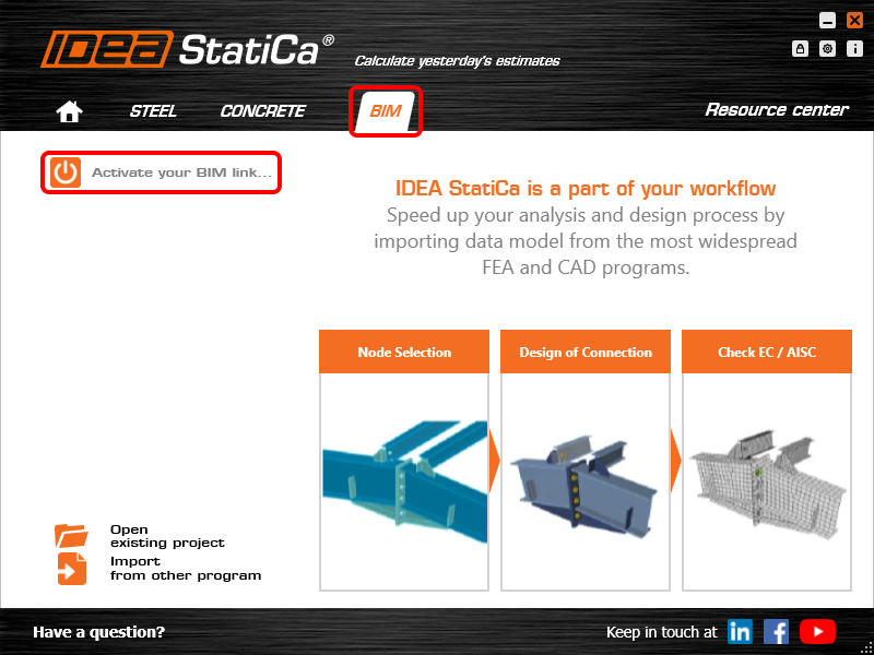
Seleccione el software para integrar el enlace BIM de IDEA StatiCa, haga clic en el botón Instalar y compruebe el estado de instalación.

2 Cómo utilizar el enlace
Primero, descargue la carpeta de origen y abra Model-Concrete hall.rtd en RSA y ejecute el análisis lineal. Seleccione las vigas 1 y 2 (64 y 75 en RSA) y abra el complemento a través de Add-Ins→IDEA StatiCa→Beam.

Cree un proyecto Nuevo y seleccione el código EN (Eurocódigo) a seguir.

Para continuar el proceso de exportación, pulse el botón Siguiente. No cambie la carpeta para guardar el proyecto. Si seleccionó una ruta diferente, el gestor de verificación normativa no podría ver ni gestionar los elementos exportados.

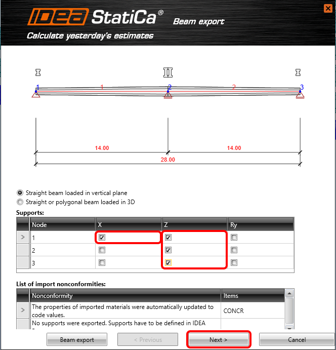
Seleccione la viga recta cargada en el plano vertical y añada Apoyos. Dicha configuración limitará el cálculo a 2D y no será posible aplicar fuerzas en el otro plano.
Seleccione la viga de hormigón prefabricado, concretamente la viga prefabricada pretensada con la opción de postensado posterior.

El peso propio se generará automáticamente en función de la sección transversal. Solo tiene que añadir la carga permanente de –4 kN/m y en este punto, establezca la carga variable en cero.

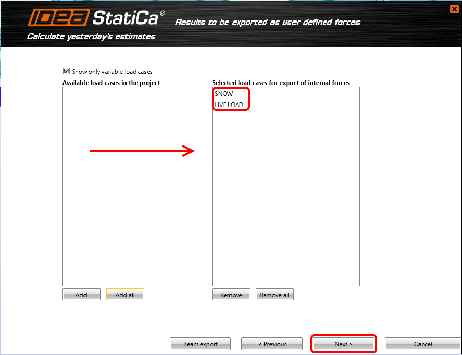
Normalmente, solo se exportan los casos de carga variable (que no afectan a la reología de la estructura). Se añaden dos casos de carga variable: NIEVE y SOBRECARGA DE USO. Estos dos casos se exportarán como fuerzas internas definidas por el usuario (My, Vz, N) del análisis global.
Ahora puede establecer las etapas particulares de construcción: la viga se pretensará en 5 días (interruptor PRE). En la etapa de Almacenamiento y Transporte, los apoyos se desplazarán 2 m desde el borde de la viga (valores L1 y L2) y habrá 1 apoyo adicional en el centro (valor n). Los apoyos finales (siguiente etapa) estarán a una distancia de 28 m. La carga muerta adicional se aplicará en 40 días.

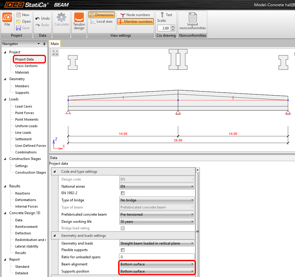
3 Proyecto de IDEA StatiCa Beam
En Datos del proyecto, alinee la viga y la posición de los apoyos con la superficie inferior.
Materiales
El grado del hormigón se importa automáticamente desde el software FEM. Sin embargo, en nuestro ejemplo, el grado importado desde RSA (C25/30) no es suficiente para elementos pretensados, por lo que se cambia directamente en IDEA StatiCa Beam (Materiales) a C40/50.

Casos de carga
Las cargas variables se asignaron automáticamente a casos de carga exclusivos. Esto significa que no se combinarán entre sí (solo uno de ellos puede entrar en una combinación).

Combinaciones
Las combinaciones EN 6.10 a,b fueron generadas automáticamente por la aplicación. Sin embargo, es necesario añadir los casos de carga variable a la etapa de construcción correspondiente. Edite (2) los casos de carga variable (3) en todas las combinaciones ELU y ELS de la etapa Fin de la vida útil.

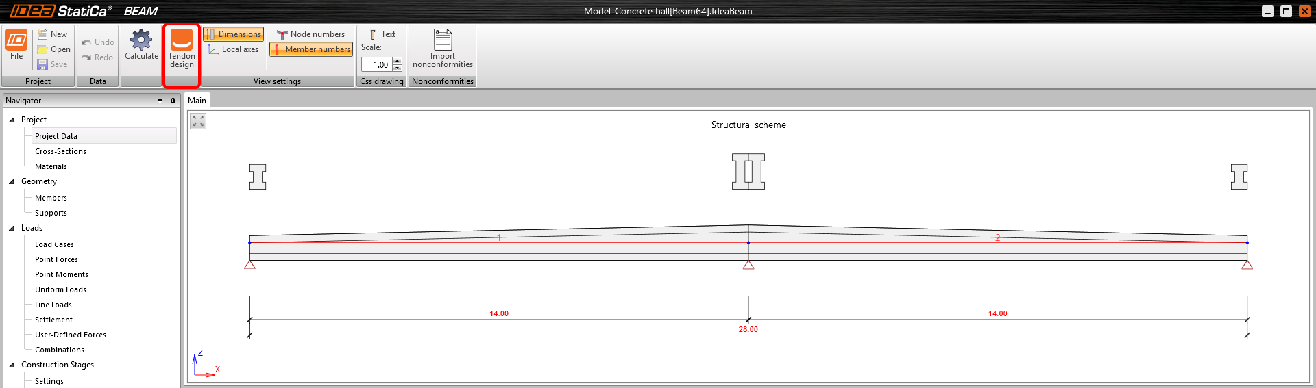
Ahora puede pasar al Diseño de tendones mediante el botón en la cinta superior.
En el árbol de la izquierda, abra Tendones – Disposición de tendones.
Ahora puede importar las plantillas preparadas. Pulse Importar – Nuevo(s) tendón(es) desde archivo TXT y cargue Prestressing tendons.nav desde la carpeta de origen.

Todos los parámetros de pretensado ya están establecidos en la plantilla.
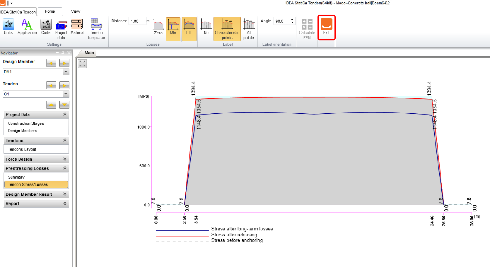
Puede ejecutar el cálculo de las pérdidas de pretensado. Abra Pérdidas de pretensado – Tensión/Pérdidas del tendón en el árbol de la izquierda y pulse Calcular FEM.

Salga del módulo una vez finalizado el análisis.
Fuerzas internas
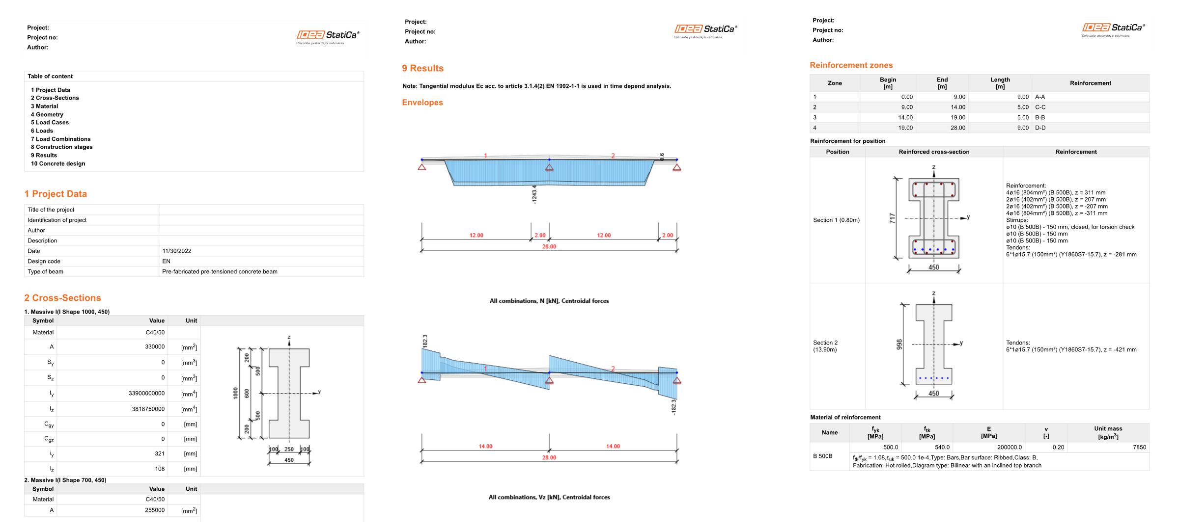
Puede visualizar los diagramas de fuerzas internas en cada una de las etapas de construcción. En el menú de la cinta superior, puede cambiar entre etapas y combinaciones. La figura siguiente presenta las fuerzas internas de la combinación ELU en la etapa 7: Fin de la vida útil.
En cada etapa, puede ver las fuerzas internas extremas y la combinación correspondiente.

En Diseño de hormigón 1D – Datos en el árbol de la izquierda, puede encontrar la configuración de las verificaciones que se evaluarán. Todas las verificaciones están activadas por defecto. Deseleccione la evaluación de Estabilidad lateral, asumiendo que está garantizada.

Armadura
Ahora añadirá algunas barras de armadura. Establezca el esquema de las zonas de armadura de la viga en las Plantillas de zonas (cinta superior). Seleccione el segundo esquema, que corresponde a una viga típica de dos vanos.

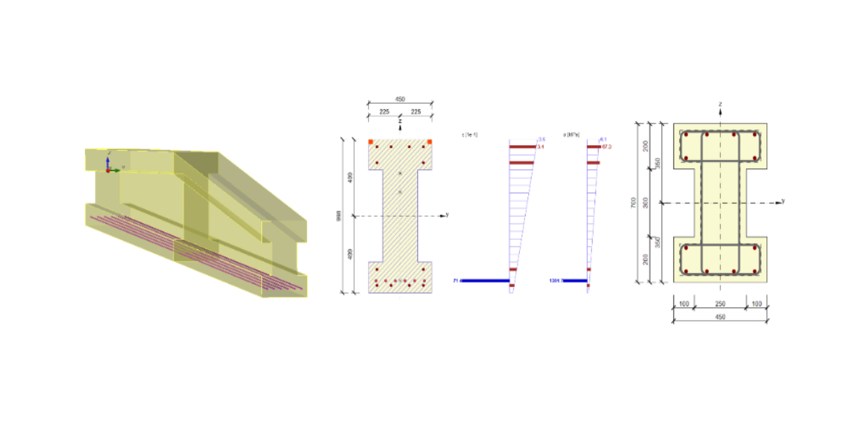
Establezca el inicio y el final de cada una de las Zonas de armadura (1) y la Posición de verificación (2) que define las secciones donde se evaluará la sección transversal de hormigón.
Primero armará la zona A–A (3) y después la zona C–C (4). Las otras dos zonas son simétricas y su armadura también será simétrica. Al hacer clic en A–A en la figura, se abre la ventana de definición de armadura.

Utilice la plantilla predefinida para armar la zona A–A. Cambie únicamente la Separación de estribos a 0,15 m.

Añada la armadura de la zona C–C mediante el mismo procedimiento. Cambie la Separación de estribos a 0,2 m.

4 Cálculo y resultados
Ejecute el cálculo del análisis TDA completo de las secciones transversales armadas haciendo clic en Resultados en el árbol de la izquierda. Una vez finalizado el cálculo, aparece el estado general de verificación con la utilización máxima. IDEA StatiCa Beam también indica en qué etapa y para qué combinación de carga aparece la utilización máxima.
Si estuviera interesado en resultados más detallados en cada sección, podría abrir la aplicación RCS mediante el botón Detallado en la cinta superior.

5 Informe
Por último, puede revisar el Informe detallado (en el árbol de la izquierda). IDEA StatiCa ofrece la posibilidad de ajustar la configuración del protocolo y también la impresión final en archivo PDF o DOC.