IDEA StatiCa Member – Estabilidad del elemento
Introducción general
IDEA StatiCa Member es un software de ingeniería estructural para el diseño estructural y la verificación normativa de elementos de acero, incluyendo sus uniones y los elementos circundantes necesarios (vigas y pilares).

Ejemplos típicos de elementos de acero no convencionales
Existen muchas herramientas excelentes para el diseño de pórticos de acero 3D – SAP2000, Robot Structural Analysis, SCIA Engineer, etc.
Cubren casi todos los requisitos de los diseñadores de estructuras de acero. Sin embargo, todavía existen problemas con muchas incógnitas. Principalmente en:
- Uniones, detalles, nodos
- Estabilidad y pandeo
IDEA StatiCa está enfocado en las partes más complejas de las estructuras de acero y ofrece:
- IDEA StatiCa Connection para la verificación de nodos y uniones de cualquier topología
- IDEA StatiCa Member para resolver todos los aspectos poco claros de estabilidad y pandeo
Todo ingeniero estructural generalmente calcula la estructura de acero en algún software de análisis por elementos finitos 3D. Luego, necesita tomar los elementos de acero uno a uno y realizar dos verificaciones principales para los elementos de acero:
- Verificación de sección
- Verificación de estabilidad
Utiliza las fuerzas internas calculadas y aplica las fórmulas de análisis definidas principalmente en el código de diseño nacional.
El mismo enfoque se aplica en Member para el acero.
El ingeniero estructural calcula la estructura de acero (pórtico) en un software de análisis por elementos finitos 3D. El elemento analizado y todos los elementos relacionados con él se separan de la estructura 3D modelada y se resuelven mediante CBFEM.
- El análisis global del pórtico de acero se realiza en un software de análisis por elementos finitos 3D.
- Todos los elementos analizados se modelan mediante CBFEM.
- Se utiliza un modelo más simplificado para todos los elementos relacionados (conectados en nodos). Los elementos relacionados pueden estar apoyados en el extremo.
- Los nodos y las uniones se diseñan en la interfaz de usuario de IDEA StatiCa Connection.
- Se pueden aplicar operaciones de fabricación específicas al elemento: rigidizadores transversales o longitudinales, aberturas, cortes...
- Las cargas pueden aplicarse sobre los elementos y en los extremos de los elementos relacionados (principio de equilibrio como en Connection).
- El elemento analizado se carga con cargas estándar derivadas de las fuerzas internas calculadas (durante la importación del modelo y los casos de carga). El usuario puede seleccionar la posición de la carga, por ejemplo, en el ala superior de la viga.
- Los elementos relacionados se cargan con cargas estándar y fuerzas internas en los extremos.

CBFEM modelo de un pilar. Un pilar analizado, cuatro elementos relacionados y un modelo preciso del anclaje

Modelo CBFEM de una viga alveolar entre dos pilares
El modelo de análisis de Member se crea mediante CBFEM. Member proporciona tres tipos de análisis:
- MNA – Análisis No Lineal Material.
- LBA – Análisis Lineal de Pandeo (estabilidad)
- GMNIA – Análisis No Lineal Geométrico y Material con Imperfecciones
Los ingenieros estructurales pueden realizar en Member, a un nivel mucho más alto, la misma verificación que en los flujos de trabajo estándar:
- Verificación de sección: se utiliza MNA. Se aplica una verificación de deformación del 5 %.
- Verificación de estabilidad: LBA indica la forma del colapso por inestabilidad y aconseja cómo debe definirse la imperfección. Posteriormente se utiliza GMNIA. Se aplica una verificación de deformación del 5 % o la consecución de la carga máxima (fin de la convergencia).
Se utiliza el mismo modelo que en IDEA StatiCa Connection – Método de los Elementos Finitos Basado en Componentes – :
Base teórica de IDEA StatiCa Connection
Descripción del modelo
La aplicación IDEA StatiCa Member trabaja con un modelo multinivel de la estructura con cargas combinadas. El objetivo es una investigación y verificación adecuada de los elementos seleccionados de una estructura – elementos "analizados".
Otras partes del modelo son:
- Elemento(s) relacionado(s) – todos los elementos que están conectados al elemento(s) analizado(s)
- Unión(es) – unión(es) CBFEM de los elementos analizados y relacionados
- Apoyos en los extremos de los elementos relacionados
- Cargas sobre el elemento analizado
- Cargas sobre los elementos relacionados
- Fuerzas en los extremos de los elementos relacionados

Modelo CBFEM de un elemento como parte de un sistema de arriostramiento sísmico
El elemento analizado se "extrae" de la estructura y se investiga por separado. Todas las cargas sobre el elemento analizado y los elementos relacionados deben aplicarse como en el modelo 3D de la estructura completa. En los puntos de "corte", que se realizan en los extremos de los elementos relacionados, las fuerzas internas se aplican como acciones sobre los elementos. La estructura extraída cargada de esta manera está en equilibrio. Esto significa que, teóricamente, no se necesitan apoyos para el modelo analítico. El modelo CBFEM es más preciso que un modelo de elemento estándar. Es una ventaja, pero también provoca una infracción parcial del equilibrio. Por lo tanto, es útil aplicar un apoyo en los extremos de las vigas relacionadas. Los apoyos deben definirse para permitir el mismo comportamiento de la estructura extraída que en la estructura completa. El programa deja esto al criterio del ingeniero estructural.
Elemento analizado
El elemento analizado es el elemento investigado sobre el cual se aplican directamente las cargas. Las cargas sobre el elemento analizado pueden aplicarse a la línea central del elemento o directamente a las placas individuales del elemento con el área real de carga. Los elementos analizados se modelan completamente con elementos de lámina.
Modelo del elemento analizado
Elementos relacionados
Los elementos relacionados se dividen en una parte de tramo corto adyacente al elemento analizado y una parte simplificada en el resto del elemento relacionado. El tramo corto se modela con elementos de lámina (modelo CBFEM completo) y las partes simplificadas con elementos de viga 1D simples con seis grados de libertad. Solo la parte necesaria cercana a la junta con el elemento analizado (el tramo corto) se modela con elementos de lámina para acelerar el cálculo. Los extremos de los elementos relacionados están apoyados mediante restricciones de traslación o rotación definidas por el usuario en una dirección arbitraria en las coordenadas locales del elemento relacionado.
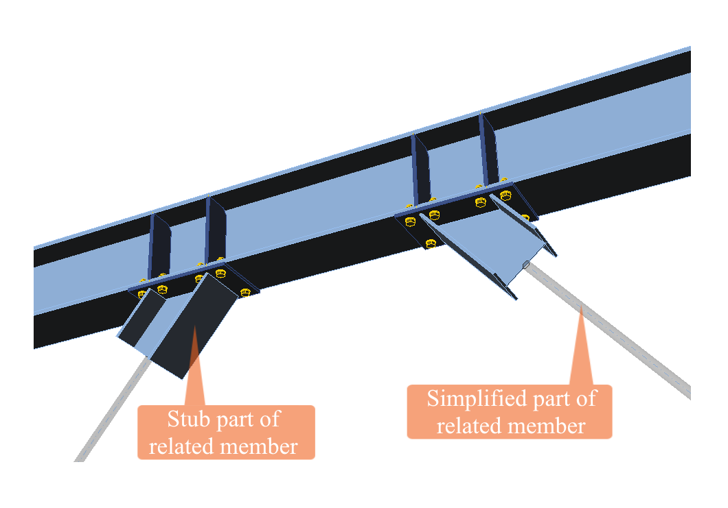
Modelo de vigas relacionadas
Uniones
Las uniones entre los elementos analizados y los relacionados se definen correctamente de la misma manera en que se modelan en IDEA StatiCa Connection. Tenga en cuenta que no se verifican en IDEA StatiCa Member, ya que esta aplicación trabaja con cargas críticas para el elemento, no para las uniones. La verificación adecuada de las uniones debe realizarse en IDEA StatiCa Connection.
Apoyos
IDEA StatiCa Member añade el segundo nivel de análisis por elementos finitos del elemento(s) seleccionado(s). El primer nivel se realiza en el programa estándar de análisis por elementos finitos 3D. El segundo nivel utiliza las fuerzas internas calculadas en el primer nivel. La estructura cargada de esta manera está en equilibrio.
Un modelo más preciso (por ejemplo, excentricidades locales de los elementos, longitudes reales de los elementos...) y especialmente las imperfecciones impuestas para el análisis GMNIA provocan que el equilibrio no se mantenga. Se recomienda un apoyo razonable basado en el criterio del ingeniero estructural.
Se pueden definir apoyos estándar en los extremos de los elementos relacionados. Las tres traslaciones y las tres rotaciones pueden eliminarse mediante el apoyo. Los apoyos se definen en el sistema de coordenadas local del elemento.

Apoyos en el extremo del elemento relacionado – correa; se apoya la dirección x y las 3 rotaciones
Cargas
El elemento analizado (o parte de una estructura) debe cargarse tal como está cargado en la estructura completa. El peso propio no se aplica automáticamente; solo se consideran las cargas definidas por el usuario. Se aplican las siguientes cargas:
- Cargas lineales sobre los elementos analizados y relacionados
- Fuerzas internas en las secciones extremas de los elementos relacionados
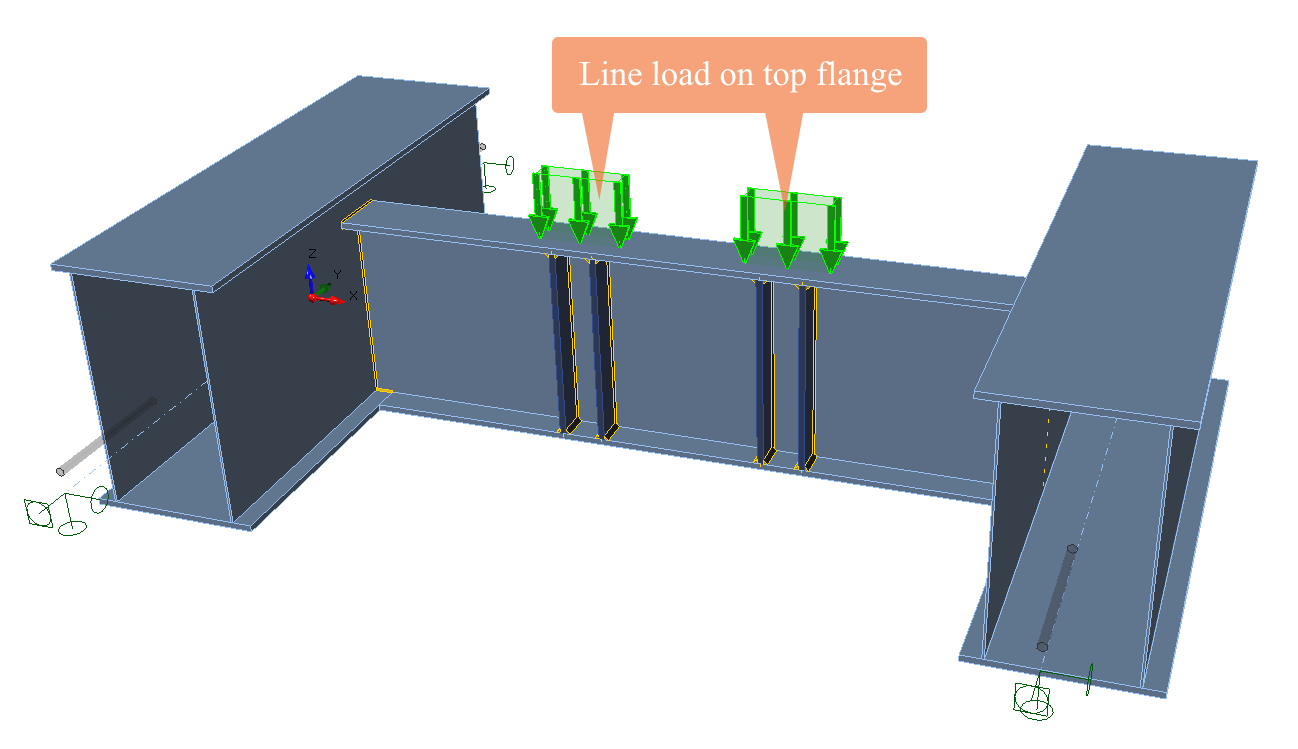
Cargas lineales
El ingeniero estructural conoce muy bien las cargas lineales y las cargas puntuales del software de análisis por elementos finitos 3D. Dichas cargas están idealizadas para el propósito de los elementos 1D. No existen en la vida real. Las cargas reales son generalmente planas, o cargas superficiales, o los elementos se cargan a través de las uniones de otros elementos.
El usuario puede aplicar cargas lineales sobre los elementos analizados, pero debe añadir más detalles: en qué ala o alma se aplica la carga, el ancho del área cargada, etc. Además, las cargas puntuales es mejor introducirlas como cargas planas de longitud y anchura específicas.
Las cargas lineales sobre los elementos relacionados se aplican de la manera estándar, como en el software de análisis por elementos finitos 3D.
La carga puntual se introduce como carga lineal con una anchura específica
Fuerzas en los extremos
Fuerzas internas en las secciones extremas de los elementos relacionados. Se aplican como acciones sobre los elementos relacionados. Es muy similar a la carga de los elementos en los modelos de uniones en IDEA StatiCa Connection.

Fuerzas internas como acciones de carga en el extremo del elemento relacionado
Ejemplo práctico
El proceso de ensamblaje del modelo CBFEM se muestra en el siguiente ejemplo.
El proyectista necesita verificar la resistencia al pandeo lateral por torsión de una viga en un pórtico. Si se utiliza el enfoque estándar, el pórtico completo se calcula en un software de análisis por elementos finitos 3D. Luego, la viga se verifica por separado. Se deciden las condiciones de contorno; los códigos generalmente utilizan la suposición de apoyos rígidos o articulados. En general, incluso puede seleccionarse un muelle de junta semirrígida. La decisión es un factor clave en la evaluación de la resistencia al pandeo lateral por torsión y depende completamente de la estimación del proyectista. Las fuerzas internas calculadas se comparan con la resistencia al pandeo lateral por torsión determinada mediante fórmulas analíticas.
La aplicación Member utiliza exactamente los mismos principios. El elemento analizado se extrae del modelo completo de la estructura. Las condiciones de contorno no se estiman, sino que todas las partes de conexión se modelan con exactitud. El problema de las condiciones de contorno no se resuelve completamente debido a la necesidad de apoyar los extremos de los elementos relacionados. Los apoyos de los elementos relacionados dependen de la decisión del proyectista, pero su influencia en la resistencia a la carga del elemento analizado es menor en varios órdenes de magnitud en comparación con el enfoque estándar.
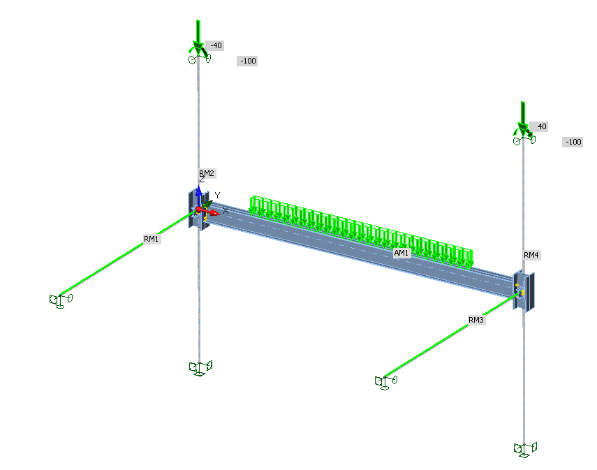
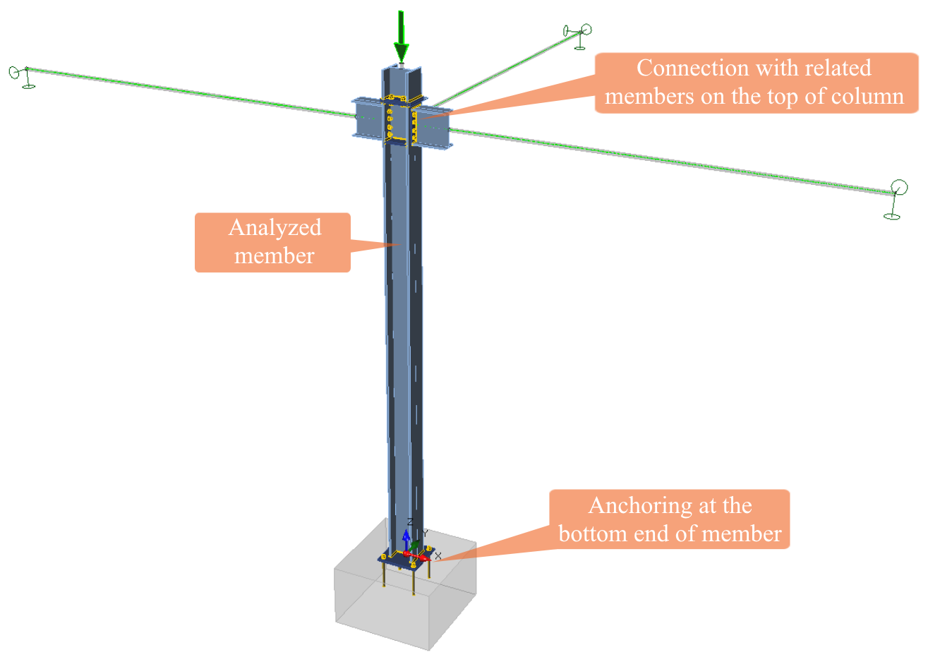
Ejemplo del modelo de viga con juntas, elementos relacionados y cargas
El elemento analizado AM1 – la viga – está cargado por una carga continua que actúa sobre el ala superior. Las juntas se modelan y verifican en IDEA StatiCa Connection.
Los pilares son los elementos relacionados en el modelo. Están empotrados en la base. En la parte superior, están apoyados únicamente en la dirección transversal (y, z). Esto permite cargar los pilares con el peso del resto de la estructura – mediante fuerza normal y momento flector en este ejemplo. Sus magnitudes corresponden a las fuerzas internas resueltas en el modelo 3D en el software de análisis por elementos finitos. No actúa ninguna otra carga sobre los pilares.
Los demás elementos relacionados son las vigas secundarias. Están simplemente apoyadas y las cargas reales se aplican sobre ellas a lo largo de toda su longitud. En sus extremos se aplican apoyos simples con la restricción adicional de rotación alrededor del eje longitudinal x.
Por supuesto, el modelo CBFEM también está de alguna manera simplificado. Sin embargo, describe el comportamiento del elemento analizado con mayor precisión que el enfoque estándar basado en fórmulas analíticas y la estimación de las condiciones de contorno y el diagrama de momentos flectores.
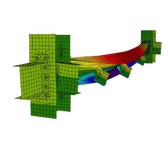
Las siguientes figuras muestran el comportamiento esperado de la viga.
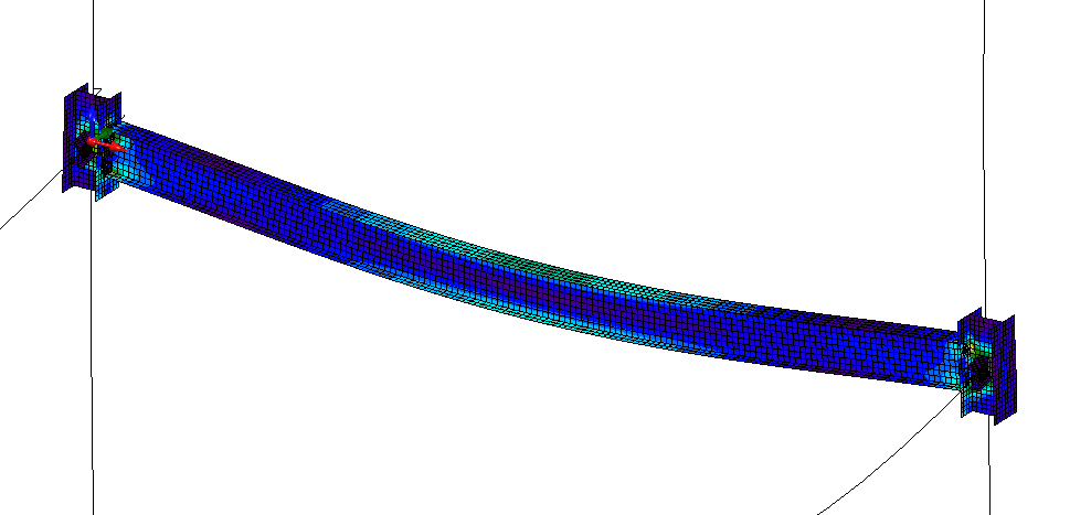
Deformación de la viga determinada por MNA

Forma del modo de pandeo determinada por LBA
Análisis
IDEA StatiCa Member es capaz de realizar tres tipos de análisis:
- Análisis No Lineal Material
- Análisis Lineal de Pandeo
- Análisis No Lineal Geométrico y Material con Imperfecciones
Los dos primeros análisis pueden utilizarse para las verificaciones normativas de los elementos, por ejemplo, mediante el Método General (EN 1993-1-1, Cl. 6.3.4), pero principalmente se utilizan para la preparación del tercer análisis, el más preciso.
Análisis No Lineal Material (MNA)
El análisis estático no lineal material y geométricamente lineal es suficiente para elementos robustos sin problemas de pandeo. El objetivo de la aplicación IDEA StatiCa Member es resolver elementos complicados, por lo que el análisis MNA generalmente no es suficiente para una evaluación completa. Este análisis es necesario para realizar otros tipos de análisis.

Diagramas de material del acero en modelos numéricos
Análisis Lineal de Pandeo (LBA)
La estructura se considera perfecta sin ninguna imperfección geométrica o material, y el material es elástico en este tipo de análisis. El análisis lineal de pandeo proporciona el factor αcr – amplificador mínimo para las cargas de cálculo para alcanzar la resistencia crítica elástica del componente estructural. El factor determina la carga cuando se alcanza la carga crítica de pandeo de Euler. La carga de pandeo real de una estructura real e imperfecta puede ser mucho menor, por lo que se recomienda un alto margen de seguridad:
- αcr > 15 – usar MNA
- αcr < 15 – usar GMNIA
Otro resultado del LBA de igual importancia es la forma del modo de pandeo. Proporciona información sobre qué parte de la estructura modelada pierde estabilidad. El usuario debe verificar todos los modos de pandeo y seleccionar los importantes para la aplicación de imperfecciones. Las formas de modo de pandeo importantes suelen causar una deflexión sinusoidal de semionada del elemento analizado o pandeo local de placas esbeltas.

Formas del modo de pandeo
La forma del modo de pandeo también nos proporciona información sobre si el elemento falla por pandeo por flexión alrededor del eje más débil o más fuerte, pandeo torsional (pilares cargados axialmente) o pandeo lateral por torsión (vigas flectadas) o pandeo local (elementos con placas esbeltas). Nótese que para estructuras complicadas, las formas del modo de pandeo pueden combinar el pandeo de varios elementos con diversas formas. Además, si se modela un pórtico completo, el pórtico pandea como un todo y no los pilares y la viga por separado.

Pandeo por flexión, torsional, pandeo lateral por torsión
Para calcular los modos de pandeo, se utiliza el algoritmo de Lanczos.
Una limitación de este algoritmo es que si existen múltiples formas de pandeo para el mismo factor de pandeo o uno muy similar, el método solo es capaz de calcular una de las formas. Esto puede ocurrir típicamente con estructuras de paredes delgadas, para las cuales las formas para un único factor de pandeo pueden adoptar muchas formas, por lo que el usuario debe ser consciente de esta limitación.
Para cada forma de modo de pandeo, siempre existe una segunda forma de modo de pandeo con el mismo factor de pandeo, pero con deformación opuesta. Esto debe tenerse en cuenta al combinar formas para crear una imperfección para GMNIA – el usuario puede querer utilizar una forma de pandeo con signo opuesto si la forma resultante es más crítica en combinación con un modo de pandeo diferente.
Las formas del modo de pandeo se utilizan directamente para la aplicación de imperfecciones en el tipo de análisis más sofisticado – GMNIA.
Análisis No Lineal Geométrico y Material con Imperfecciones (GMNIA)
El análisis no lineal geométrico y material con imperfecciones es el tipo de análisis más sofisticado para cargas estáticas. Todas las imperfecciones (variación del espesor de las placas, falta de rectitud, tensiones residuales, no homogeneidades en el material, desalineación de apoyos...) se sustituyen por imperfecciones geométricas equivalentes y pueden establecerse utilizando las formas del modo de pandeo calculadas por LBA. El usuario selecciona la amplitud máxima de la forma del modo de pandeo utilizada para la imperfección. La descripción de las imperfecciones se encuentra en el siguiente capítulo.
Interpretación de resultados
La mayoría de los códigos de diseño reconocen dos estados límite – servicio y último.
Estado límite de servicio
Los códigos de diseño establecen límites de deflexión de los elementos. Estos pueden verificarse comparando la deflexión del elemento analizado con los límites.
Estado límite último
El estado límite último puede alcanzarse por la consecución de un valor límite de la deformación principal de membrana – recomendado como 5 % o por la consecución de la carga máxima para elementos susceptibles al pandeo. La carga máxima se alcanza cuando el solver deja de converger (porque el modelo se carga por fuerzas y no por desplazamientos). El fin de la convergencia significa que no se puede aplicar ningún incremento de carga al modelo, y el análisis puede detenerse por debajo del 100 % de la carga definida. La rama descendente del diagrama carga-deformación no puede capturarse.

Fin de la convergencia en GMNIA
Imperfecciones
Las imperfecciones son inexactitudes en los apoyos, tensiones residuales en los elementos, espesores variables de las placas, falta de rectitud de los elementos, etc. Todas estas imperfecciones se simulan mediante imperfecciones geométricas equivalentes. Pueden considerarse tres tipos de imperfecciones geométricas:
- Imperfecciones globales de la estructura
- Imperfecciones locales de los elementos
- Imperfecciones locales de placas de elementos esbeltos
Existen directrices en, por ejemplo, EN 1993-1-1 y EN 1993-1-5 para cada tipo de imperfección.
Nótese que, en general, deben investigarse las formas de imperfección con signos positivos y negativos (diferentes direcciones). Solo si la geometría es simétrica, ambas direcciones de imperfección proporcionan los mismos resultados, y solo una puede investigarse.
Imperfecciones globales
Las imperfecciones globales de la estructura se describen en EN 1993-1-1, Cl. 5.3.2 (3). La estructura debe inclinarse en forma de imperfección de desplome equivalente según la siguiente figura.
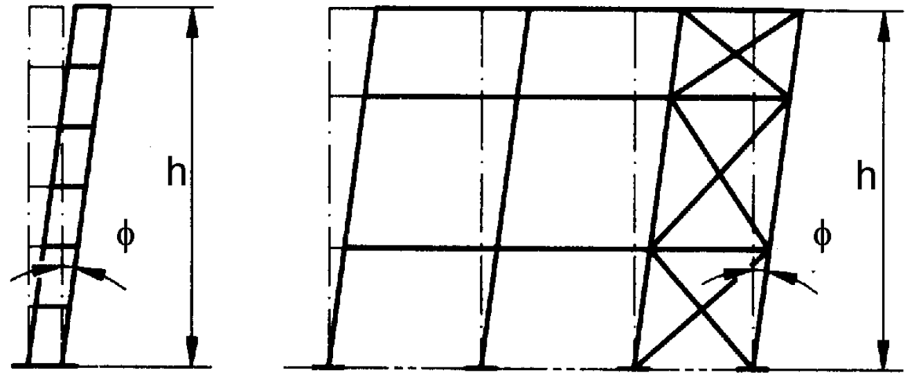
Imperfección de desplome equivalente (de EN 1993-1-1 – Figura 5.2)
El ángulo de imperfección es:
\[ \phi = \phi_0 α_h α_m \]
donde:
- ϕ0 = 1/200 – valor básico de la imperfección
- \( 2/3 \le α_h = \frac{2}{\sqrt{h}} \le 1.0 \) – factor de reducción por altura h aplicable a pilares
- h – altura de la estructura en metros
- \( \alpha_m = \sqrt{0.5 \left ( 1+\frac{1}{m} \right )} \) – factor de reducción por el número de pilares en una fila
- m – número de pilares en una fila, incluyendo solo aquellos pilares que soporten una carga vertical NEd no inferior al 50 % del valor medio del pilar en el plano vertical considerado
Las imperfecciones globales deben aplicarse a la estructura en el modelo de análisis global para obtener cargas correctas. Las imperfecciones globales no necesitan aplicarse también al modelo en la aplicación IDEA StatiCa Member si, por ejemplo, solo se analiza una viga.
Imperfecciones locales de los elementos
Las imperfecciones locales de los elementos se describen en EN 1993-1-1, Cl. 5.3.2 (3). Las imperfecciones se consideran en forma de imperfección de curvatura local con la amplitud e0/L, donde L es la longitud teórica del elemento (distancia nodo a nodo).
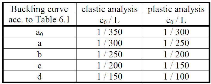
Valores de cálculo de las imperfecciones de curvatura local iniciales (de EN 1993-1-1 – Tabla 5.1)
Se utiliza el análisis plástico, por lo que debe utilizarse la columna derecha de la tabla. La amplitud e0 debe elegirse según la tabla anterior para elementos predominantemente comprimidos donde se espera pandeo por flexión, torsional o torsional-flexional. Si el elemento está predominantemente flectado y el modo de fallo principal es el pandeo lateral por torsión, la amplitud e0 puede reducirse mediante el factor k = 0,5 según EN 1993-1-1, Cl. 5.3.4 (3).
Se muestran dos ejemplos:
Ejemplo 1: Pilar
Un pilar con una longitud de 4 m está cargado por fuerza axial y tiene αcr = 1,4 para pandeo alrededor del eje más fuerte y αcr = 1,5 alrededor del eje más débil. Los demás valores son significativamente más altos. Deben verificarse dos casos:
- Pandeo alrededor del eje más fuerte: Según la Tabla 6.2, se selecciona la curva de pandeo a, que corresponde a una amplitud de imperfección e0 / L = 1 / 250 para análisis plástico. Por lo tanto, se aplica una amplitud de 4000 / 250 = 16 mm a la primera forma del modo de pandeo. Se ejecuta GMNIA y se evalúan los estados límite.
- Pandeo alrededor del eje más débil: Según la Tabla 6.2, se selecciona la curva de pandeo b, que corresponde a una amplitud de imperfección e0 / L = 1 / 200 para análisis plástico. Por lo tanto, se aplica una amplitud de 4000 / 200 = 20 mm a la segunda forma del modo de pandeo. Se ejecuta GMNIA y se evalúan los estados límite.
Debe utilizarse la resistencia a la carga mínima. Alternativamente, ambos modos de pandeo pueden utilizarse al mismo tiempo, lo que conduce a un resultado más seguro y un tiempo de cálculo más rápido.
Ejemplo 2: Viga
Una viga con un vano teórico (distancia nodo a nodo) de 6 m está cargada por carga transversal. LBA muestra que la primera forma del modo de pandeo es el pandeo lateral por torsión con αcr = 1,9. Las demás formas del modo de pandeo tienen valores de αcr significativamente más altos. Según la Tabla 6.4, se selecciona la curva de pandeo a, que corresponde a una amplitud e0 / L = 1 / 250. Dado que se investiga el pandeo lateral por torsión, puede utilizarse el factor k0 = 0,5. Se aplica una amplitud de 0,5 • 6000 / 250 = 12 mm al primer modo de pandeo. Se ejecuta GMNIA y se evalúan los estados límite.
Imperfecciones locales de placas de elementos esbeltos
Si los elementos son de clase 4, también deben aplicarse imperfecciones locales de las placas. La amplitud de la imperfección del panel debe ser a / 200, donde a es el lado más corto del panel según EN 1993-1-5, Cl. C.5.
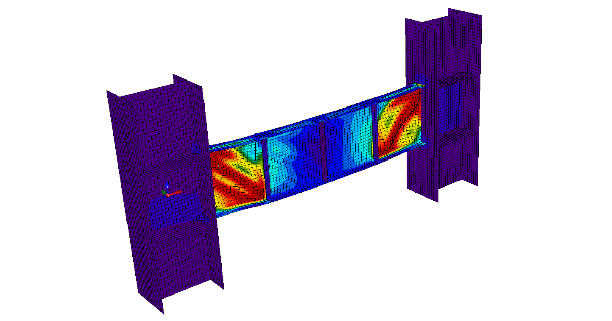
Pandeo local de placas esbeltas
Aunque GMNIA debería ser un análisis adecuado para la evaluación de elementos esbeltos, actualmente no se han realizado suficientes verificaciones y validaciones para confirmar que el modelo es seguro. Por lo tanto, por ahora no se recomienda utilizar IDEA StatiCa Member para elementos esbeltos (clase 4).
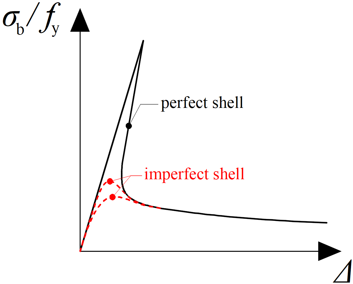
Influencia de las imperfecciones en el análisis numérico de placas esbeltas
Aplicación de imperfecciones en IDEA StatiCa Member
IDEA StatiCa Member permite aplicar imperfecciones en las formas del modo de pandeo con la amplitud máxima elegida por el usuario en valor absoluto. Generalmente, la primera forma del modo de pandeo con la amplitud máxima según la Tabla 5.1 de EN 1993-1-1 es suficiente. Para elementos con clase de sección transversal 4, deben considerarse más formas del modo de pandeo y utilizarse una combinación de al menos dos modos de pandeo. Especialmente para un modelo con más elementos analizados, deben seleccionarse varias formas del modo de pandeo.
Las imperfecciones geométricas son equivalentes y no deben entrar en la evaluación de los resultados, por ejemplo, la deflexión en el estado límite de servicio. Por lo tanto, al visualizar los resultados, solo se muestran las deflexiones debidas a la carga sobre una estructura no deformada por imperfecciones.
Diseño avanzado según AISC 360-16
AISC 360-16 no hace referencia directa al diseño de elementos mediante análisis por elementos finitos con elementos de lámina, por lo que se recomienda utilizar una guía mucho más detallada en EN 1993-1-5. El Comm. 1.3.3b hace referencia a ECCS: Ultimate Limit State Calculation of Sway Frames with Rigid Joints (1984), donde se utiliza el concepto de imperfección geométrica equivalente. El diseño mediante análisis inelástico se trata en el Apéndice 1.3. El análisis inelástico deberá tener en cuenta:
- deformaciones de los elementos por flexión, cortante, axial y torsión, y todas las demás deformaciones de componentes y uniones que contribuyen a los desplazamientos de la estructura – cubierto mediante el uso de GMNIA y elementos compuestos por elementos de lámina
- efectos de segundo orden (incluyendo efectos P-Δ, P-δ y de torsión) – cubierto mediante el uso de GMNIA
- imperfecciones geométricas – establecidas por el usuario mediante la forma del modo de pandeo del análisis LBA
- reducciones de rigidez debidas a la inelasticidad, incluyendo la plastificación parcial de la sección transversal que puede acentuarse por la presencia de tensiones residuales – no es posible establecer tensiones residuales en el elemento. Sin embargo, utilizando el Apéndice 1.3.3c, el modelado de tensiones residuales puede sustituirse por una reducción del módulo elástico, E, y del módulo a cortante, G, en un factor de 0,8.
- incertidumbre en la resistencia y rigidez del sistema, los elementos y las uniones – cubierto mediante el uso de imperfecciones geométricas y reducción de rigidez
El Apéndice 1.3.3b establece: "En todos los casos, el análisis deberá modelar directamente los efectos de las imperfecciones iniciales debidas tanto a los puntos de intersección de los elementos desplazados de sus posiciones nominales (imperfecciones del sistema), como a la falta de rectitud inicial o desviaciones de los elementos a lo largo de su longitud (imperfecciones del elemento). La magnitud de los desplazamientos iniciales deberá ser la cantidad máxima considerada en el diseño; el patrón de desplazamientos iniciales deberá ser tal que proporcione el mayor efecto desestabilizador."
Las imperfecciones geométricas se describen en el Comm. C2.2: "Las imperfecciones geométricas iniciales se asumen de forma conservadora iguales a las tolerancias máximas de material, fabricación y montaje permitidas en el Código de Práctica Estándar de AISC (AISC, 2016a): una falta de rectitud del elemento igual a L / 1000, donde L es la longitud del elemento entre puntos de arriostramiento o enmarcado, y una falta de plomada del pórtico igual a H / 500, donde H es la altura del piso."
Se recomienda aplicar la falta de plomada en el software de análisis por elementos finitos 3D y la falta de rectitud en la aplicación IDEA StatiCa Member.
Resumen:
Si se decide utilizar el enfoque AISC, aplique una falta de plomada H / 500 en el software de análisis por elementos finitos 3D, una falta de rectitud L / 1000 en Member y reduzca el módulo de elasticidad a tracción/compresión y a cortante por un factor de 0,8. Nótese que este procedimiento no cubre problemas complicados con varios factores del modo de pandeo próximos entre sí.