
Přípoj k nevyztuženým pásnicím
Popis
V této kapitole je metoda konečných prvků na bázi komponent (CBFEM) koutového svaru spojujícího plech s nevyztuženým sloupem ověřena pomocí komponentové metody (CM). Ocelový plech je připojen k sloupu s otevřeným a uzavřeným průřezem a zatížen tahem.
Analytický model
Koutový svar je jediná komponenta zkoumaná v této studii. Svary jsou navrženy podle kapitoly 4 v EN 1993-1-8:2005 jako nejslabší komponenta ve styčníku. Návrhová únosnost koutového svaru je popsána v oddílu 4.1. Síla působící kolmo na ohebný plech přivařený k nevyztuženému průřezu je omezena. Napětí se soustřeďuje v účinné šířce, zatímco únosnost svaru v oblasti nevyztužených částí je zanedbána, jak je znázorněno na obr. 4.5.1. Pro nevyztužený průřez I nebo H se účinná šířka stanoví podle:
\[ b_\mathrm{eff} = t_\mathrm{w} + 2s + 7kt_\mathrm{f} \qquad (4.5.1)\]
\[ k = \frac{t_\mathrm{f} \cdot f_\mathrm{y,f} }{ t_\mathrm{p} \cdot f_\mathrm{y,p}} \qquad (4.5.2)\]
Rozměr s je pro válcovaný průřez \(s =r\) a pro svařovaný průřez \(s = \sqrt{2} \cdot a \) . Pro uzavřený nebo U průřez se účinná šířka stanoví z:
\[ b_\mathrm{eff} = 2t_\mathrm{w} + 5 t_\mathrm{f} \quad \textrm{but}\quad b_\mathrm{eff} \leq 2t_\mathrm{w} + 5 kt_\mathrm{f}\qquad (4.5.1)\]
\[\sqrt{ \sigma_{\perp}^2 + 3 \cdot \left( \tau_{\perp}^2 + \tau_{\parallel}^2\right)} \leq \frac{f_u}{\beta_{\mathrm{w}} \cdot \gamma_{\mathrm{M2}}}\]
\[\sigma_{\perp} = \tau_{\perp} = \frac{\sigma_{N}}{\sqrt{2}} = \frac{N}{b_\mathrm{eff} \cdot a}\cdot \frac{1}{\sqrt{2}} \]
\[ \tau_{\parallel} = 0\]
\[ \sqrt{ \left( \frac{\sigma_{N}}{\sqrt{2}} \right)^2 + 3 \cdot \left( \frac{\sigma_{N}}{\sqrt{2}} \right)^2} \leq \frac{f_u}{\beta_{\mathrm{w}} \cdot \gamma_{\mathrm{M2}}}\]
\[ \sqrt{ \left( \frac{N}{b_\mathrm{eff} \cdot a}\cdot \frac{1}{\sqrt{2}} \right)^2 + 3 \cdot \left( \frac{N}{b_\mathrm{eff}\cdot a}\cdot \frac{1}{\sqrt{2}} \right)^2} \leq \frac{f_u}{\beta_{\mathrm{w}} \cdot \gamma_{\mathrm{M2}}}\]
\[ N \leq \frac{f_{u} \cdot b_\mathrm{eff} \cdot a }{\beta_{\mathrm{w}} \cdot \gamma_{\mathrm{M2}} \cdot \sqrt{2}} \]
Kde:
\(a\) - výška koutového svaru
\(N\) - normálová síla působící na nosník
\(b_\mathrm{eff}\) - celková účinná délka svarů
\(\beta_{\mathrm{w}}\) - korelační součinitel převzatý z tabulky 4.1 EN 1993-1-8
\(f_u\) - jmenovitá mez pevnosti slabšího spojovaného prvku
\(\gamma_{\mathrm{M2}}\) - dílčí součinitel spolehlivosti pro svary
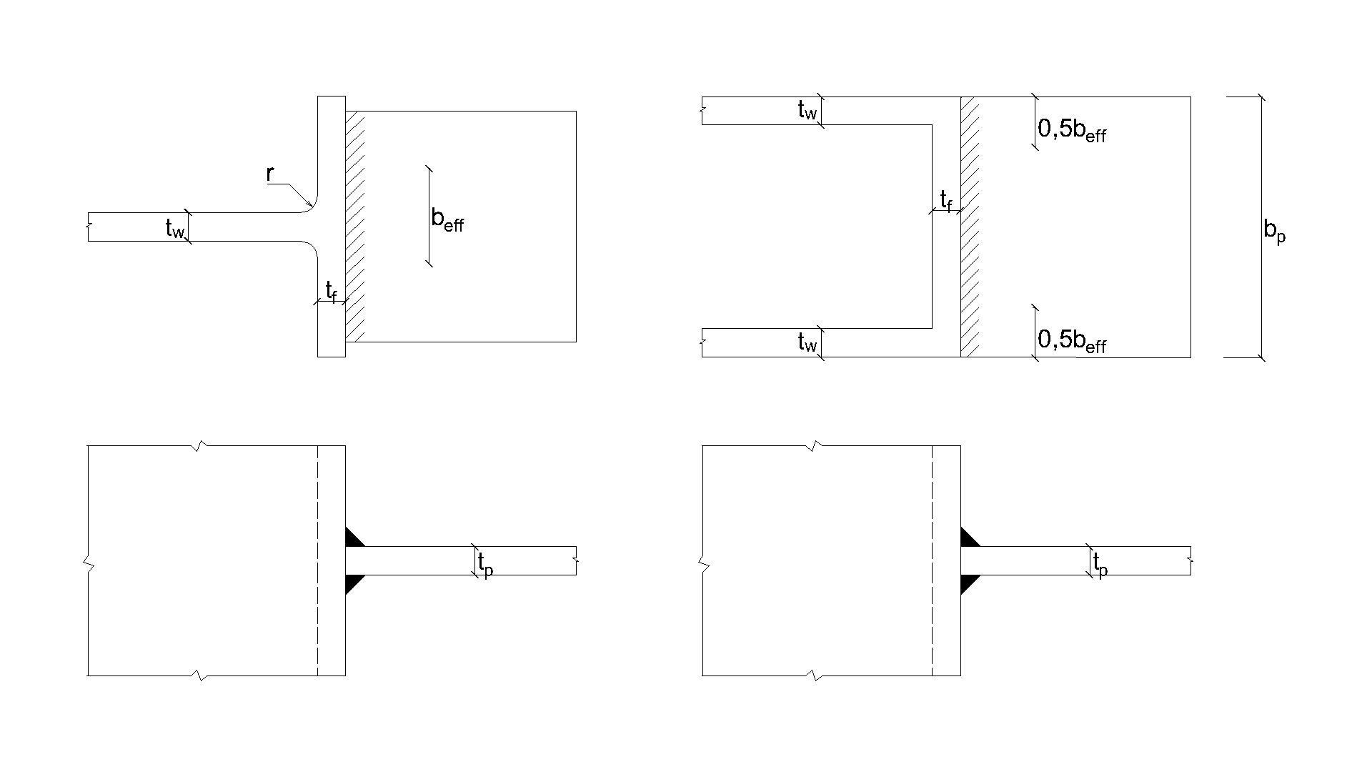
\[ \textsf{\textit{\footnotesize{Fig. 4.5.1 Effective width of an unstiffened joint (Fig. 4.8 in EN 1993-1-8:2005)}}}\]
Numerický model
Komponenta svaru v CBFEM je popsána v obecném teoretickém pozadí a teoretickém pozadí EN. Plastická větev je dosažena v části svaru a napěťové špičky jsou přerozděleny podél délky svaru.
Ověření únosnosti
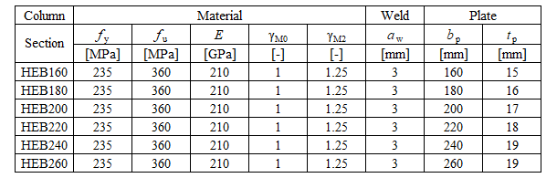
Návrhová únosnost vypočtená pomocí CBFEM je porovnána s výsledky CM. Porovnává se pouze návrhová únosnost svaru. Přehled uvažovaných příkladů a materiálu je uveden v tab. 4.5.1. Geometrie styčníků s rozměry je znázorněna na obr. 4.5.2.
\[ \textsf{\textit{\footnotesize{Tab. 4.5.1 Examples overview}}}\]
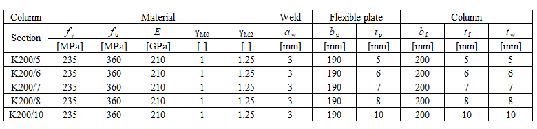
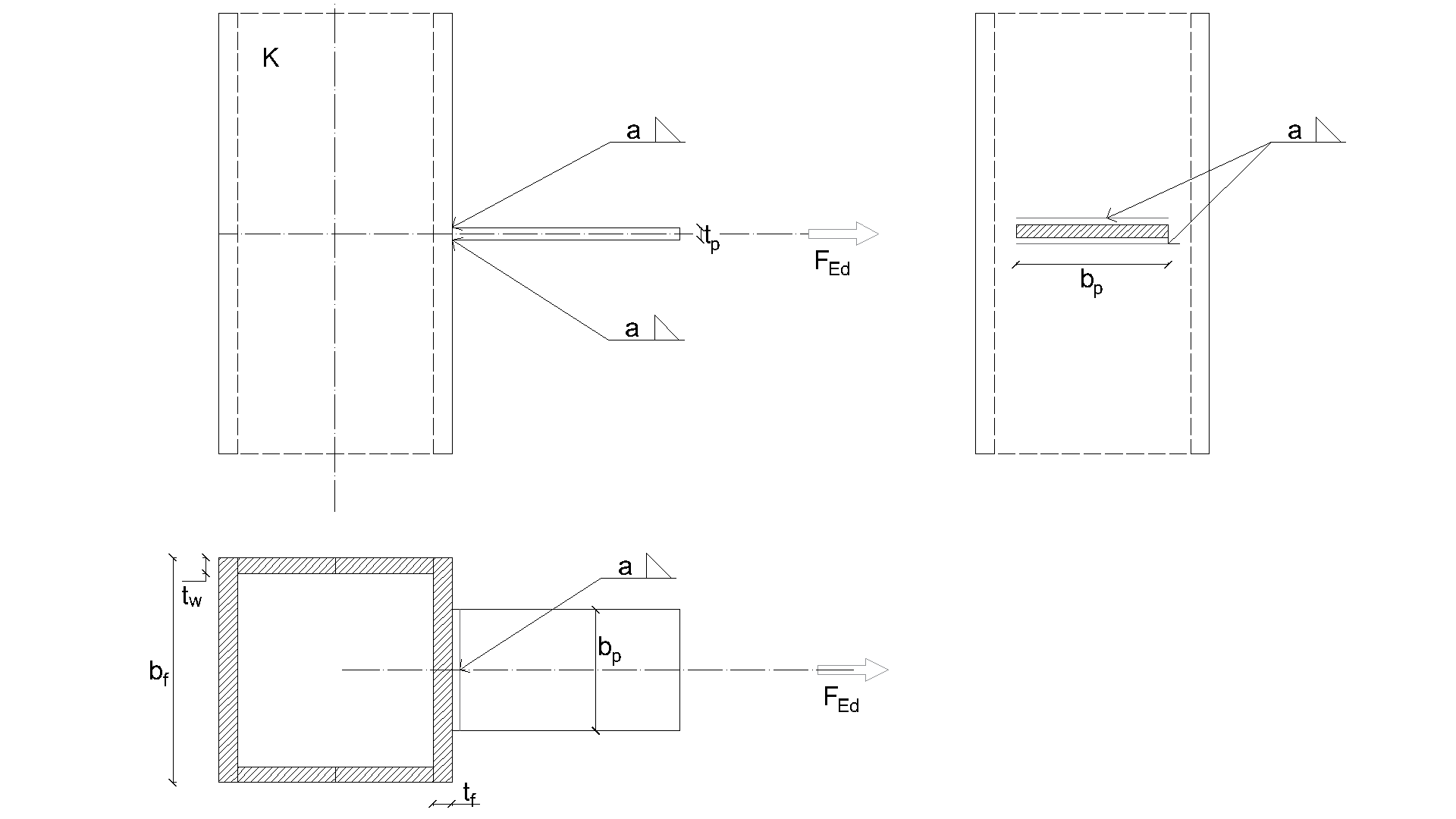
\[ \textsf{\textit{\footnotesize{a) Flexible plate to open section b) Flexible plate to box section}}}\]
\[ \textsf{\textit{\footnotesize{Fig. 4.5.2 Joint geometry and dimentions}}}\]
Výsledky jsou uvedeny v tab. 4.5.2. Studie je provedena pro dva parametry: šířku pásnice průřezu HEB a tloušťku stojiny uzavřeného průřezu. Ohebný plech je zatížen tahem. Vliv šířky pásnice průřezu HEB na návrhovou únosnost styčníku je znázorněn na obr. 4.5.3. Závislost tloušťky stojiny uzavřeného průřezu na návrhové únosnosti styčníku je znázorněna na obr. 4.5.4.
\[ \textsf{\textit{\footnotesize{Tab. 4.5.2 Comparison of CBFEM and CM}}}\]

Výsledky CBFEM a CM jsou porovnány v parametrické studii. Vliv šířky pásnice průřezu HEB na návrhovou únosnost styčníku je studován na obr. 4.5.3. Vliv tloušťky stojiny uzavřeného průřezu na návrhovou únosnost styčníku je uveden na obr. 4.5.4. Parametrické studie vykazují velmi dobrou shodu výsledků pro všechny konfigurace svarů.
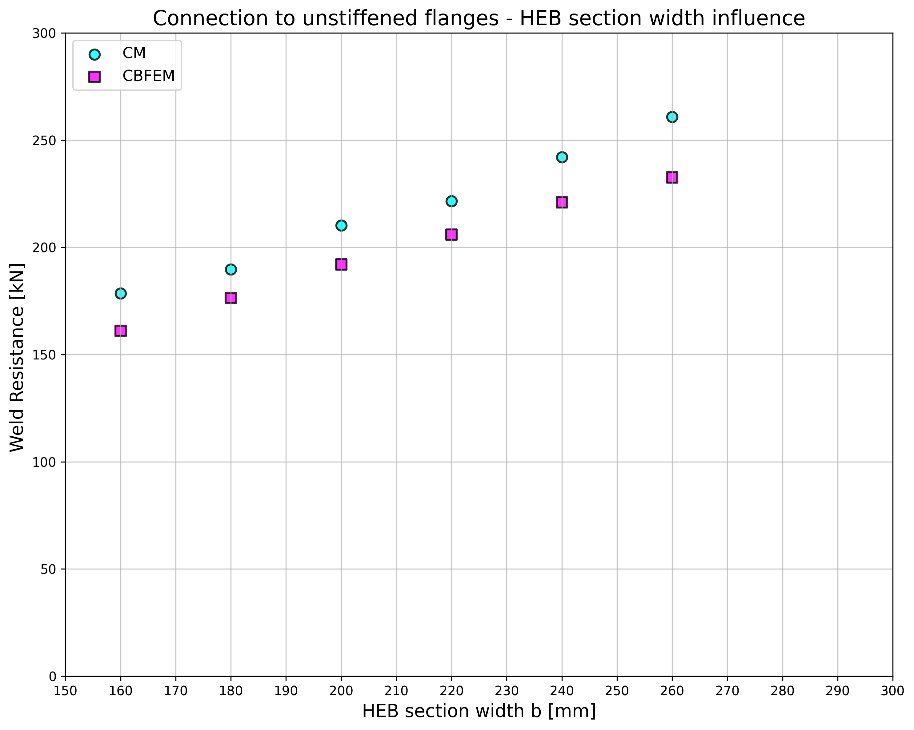
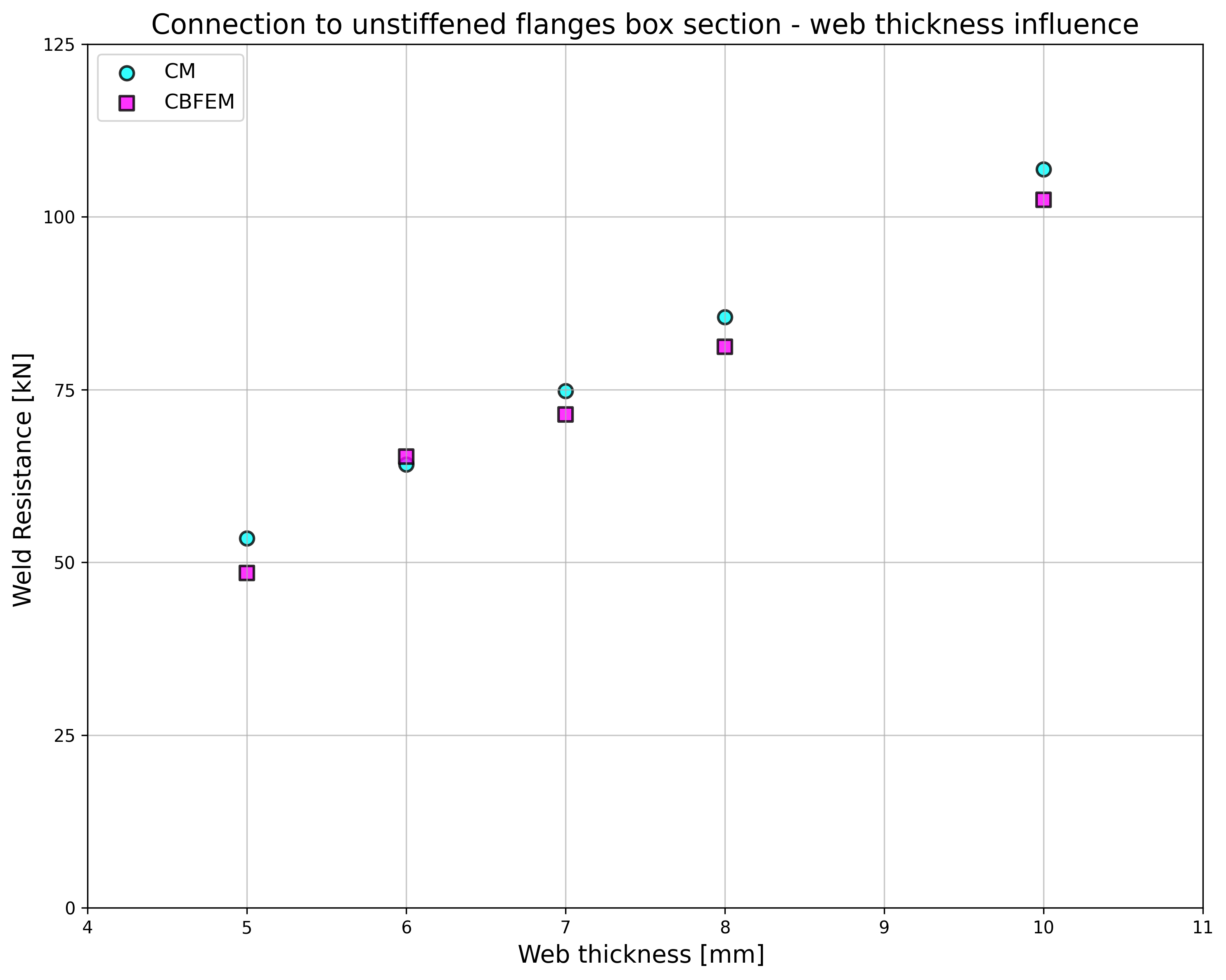
\[ \textsf{\textit{\footnotesize{Fig. 4.5.3 Flange width of the HEB section Fig. 4.5.4 Web thickness of the box section}}}\]
Výsledky parametrické studie jsou shrnuty v diagramu porovnávajícím návrhové únosnosti CBFEM a CM; viz obr. 4.5.5 ilustrující přesnost modelu CBFEM.
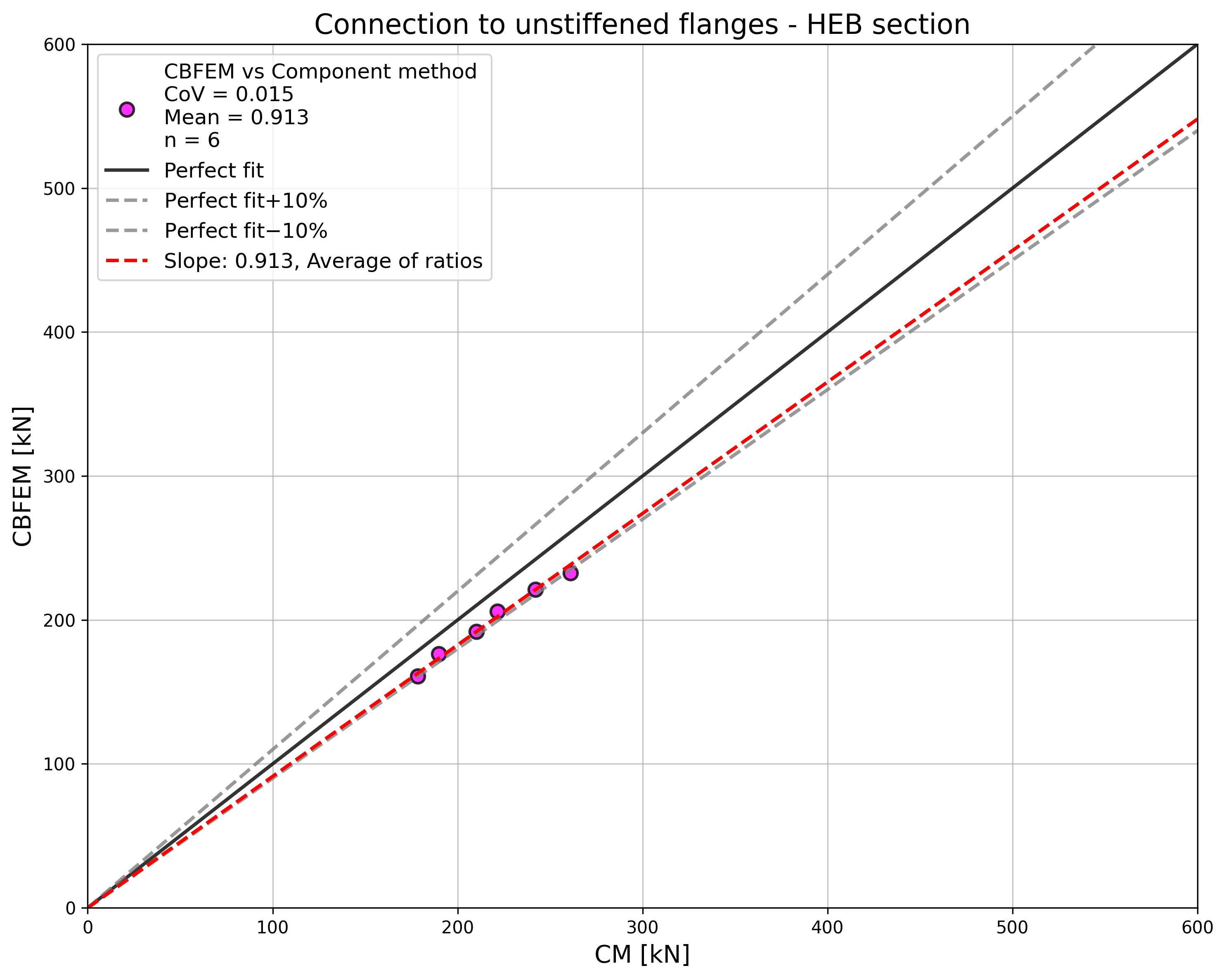
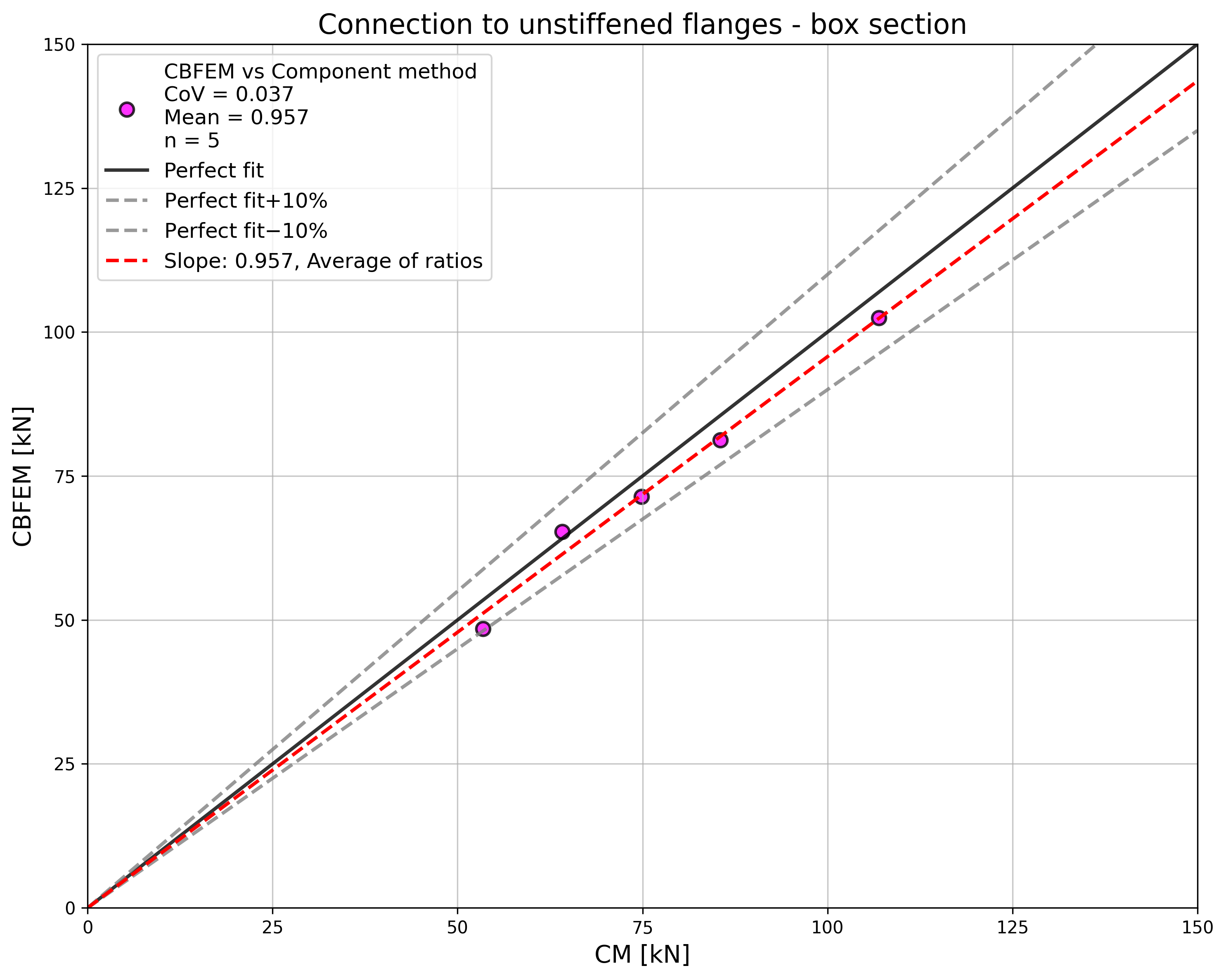
\[ \textsf{\textit{\footnotesize{Fig. 4.5.5 Verification of CBFEM to CM}}}\]
Vliv tloušťky plechu na návrhovou únosnost svaru je znázorněn na obr. 4.5.6. Průřez sloupu je HEB 180 s tloušťkou pásnice 14 mm. Svar spojující plech silnější než pásnice sloupu má stejnou únosnost pro CM i CBFEM. Naopak svar spojující plech s pásnicí sloupu stejné nebo menší tloušťky má v numerických modelech návrhovou únosnost nižší o 20 %. Tloušťka plechu není v numerických modelech se skořepinovými prvky zohledněna, což způsobuje tento rozdíl.
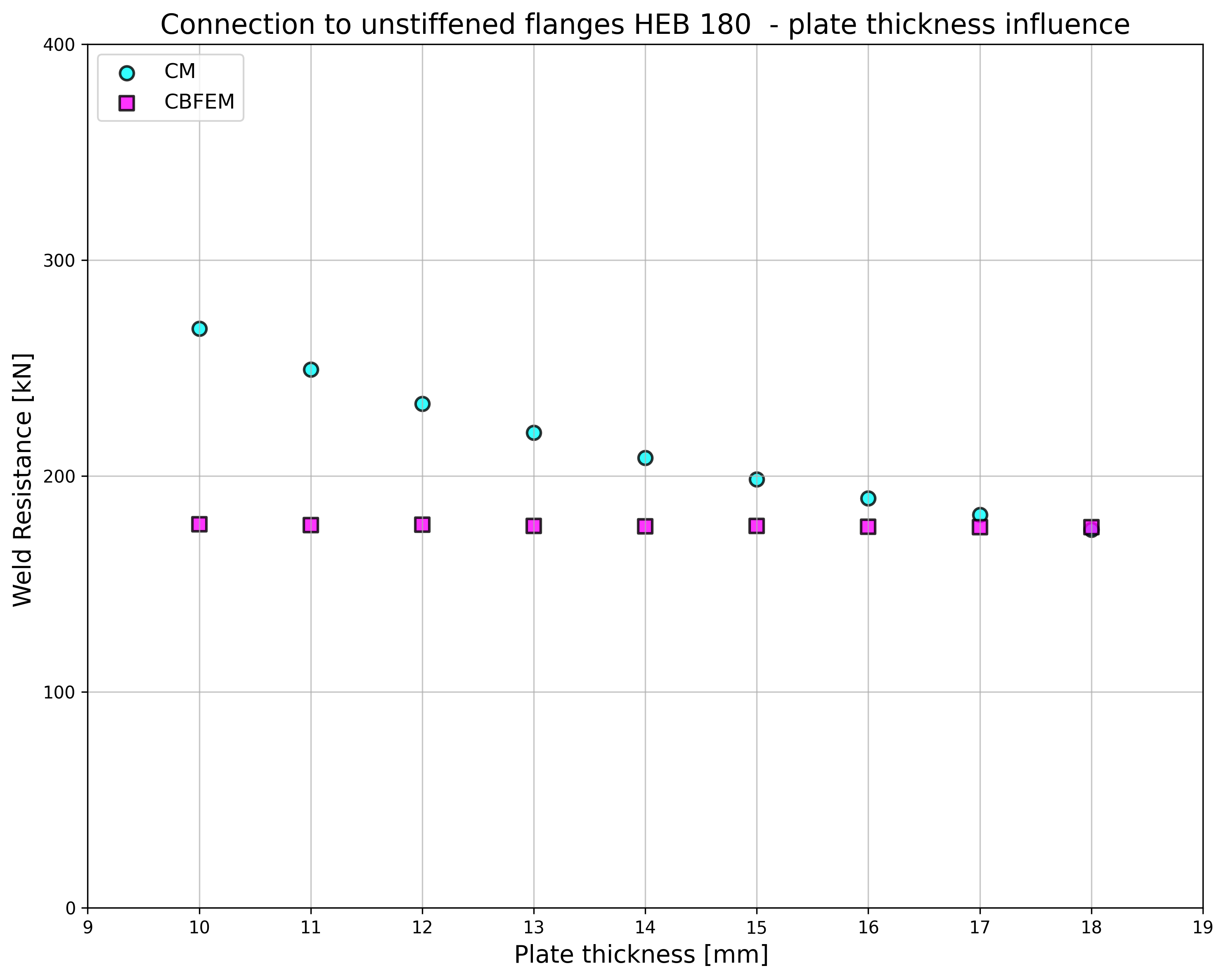
\[ \textsf{\textit{\footnotesize{Fig. 4.5.6 Influence of plate thickness on the resistance of joint with unstiffened column HEB180}}}\]
Srovnávací příklad
Vstupy
Sloup
• Ocel S235
• RHS 200/200/5
Ohebný plech
• Ocel S235
• Tloušťka tp = 17 mm
• Šířka bp = 190 mm
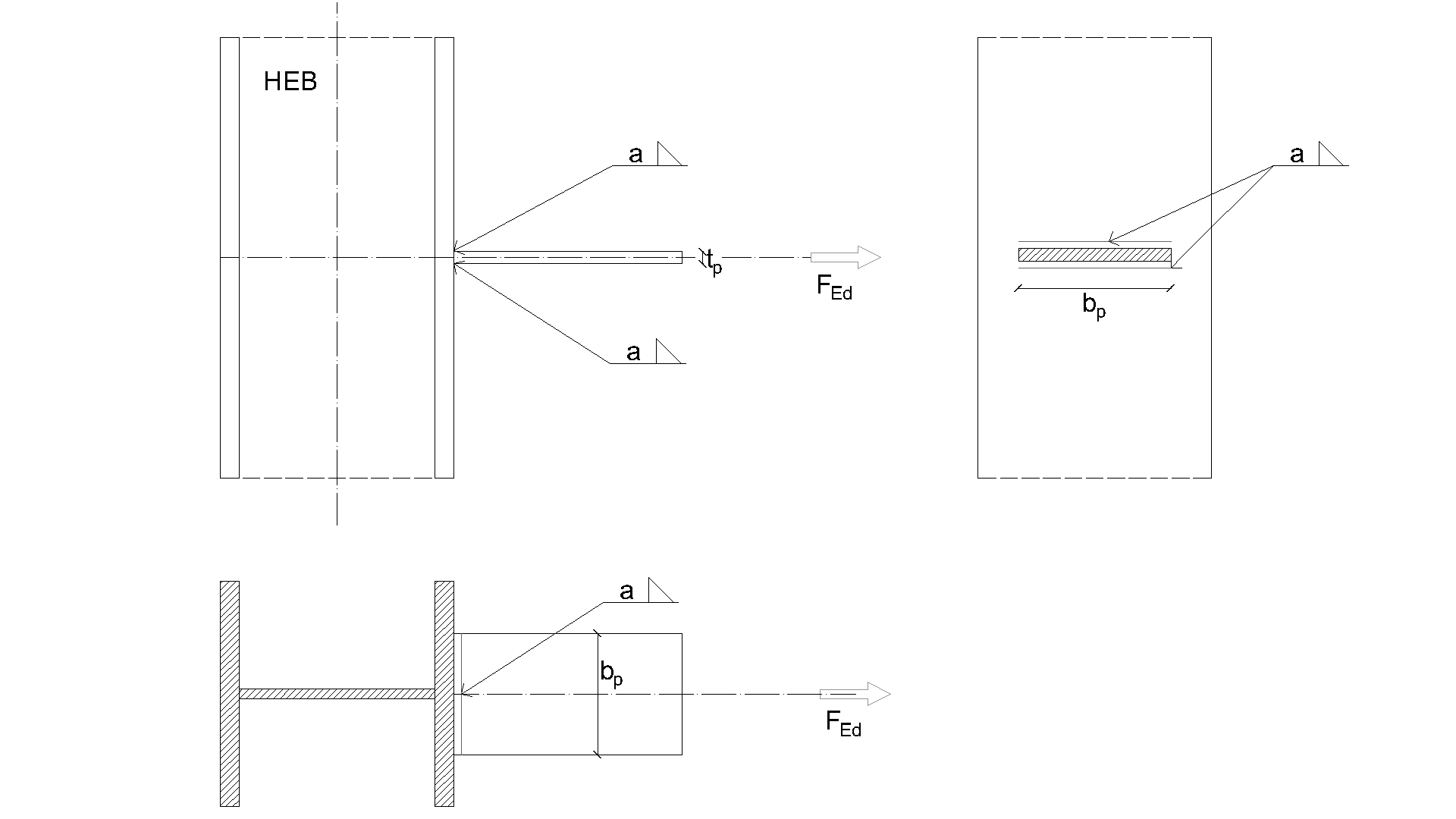
Svar, dvojité koutové svary viz obr. 4.5.7
• Výška svaru aw = 5 mm
Výstupy
• Návrhová únosnost v tahu NRd = 68 kN
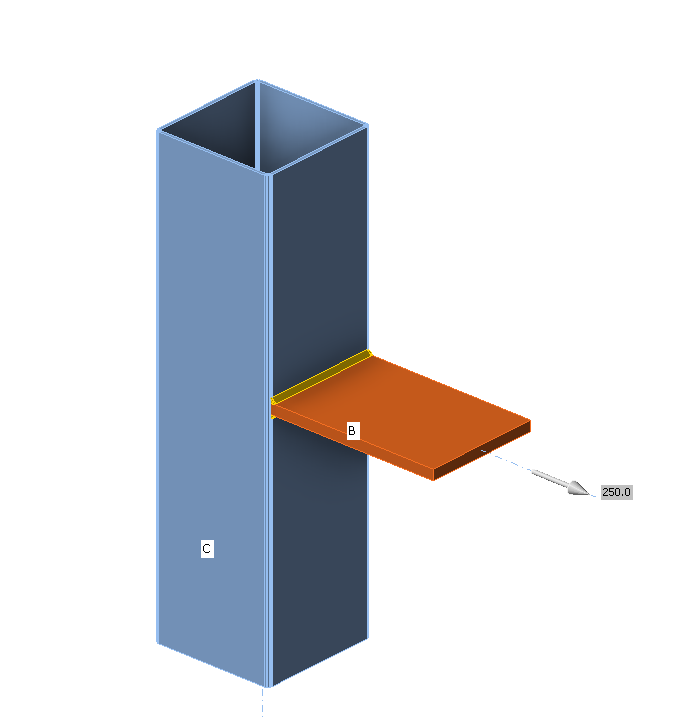
\[ \textsf{\textit{\footnotesize{Fig. 4.5.7 Benchmark example for the welded connection of plate to unstiffened column}}}\]