
Collegamento a flange non irrigidite
Descrizione
In questo capitolo, il metodo degli elementi finiti basato sui componenti (CBFEM) di una saldatura d'angolo che collega una piastra a una colonna non irrigidita viene verificato con il metodo delle componenti (CM). La piastra in acciaio è collegata a colonne a sezione aperta e a sezione cava e caricata a trazione.
Modello analitico
La saldatura d'angolo è l'unica componente esaminata nello studio. Le saldature sono progettate secondo il Capitolo 4 della EN 1993-1-8:2005 per essere la componente più debole nel giunto. La resistenza di progetto della saldatura d'angolo è descritta nella Sezione 4.1. La forza applicata perpendicolarmente a una piastra flessibile, saldata a una sezione non irrigidita, è limitata. Le tensioni sono concentrate in una larghezza efficace mentre la resistenza della saldatura attorno alle parti non irrigidite è trascurata, come mostrato in Fig. 4.5.1. Per una sezione I o H non irrigidita, la larghezza efficace si ottiene secondo:
\[ b_\mathrm{eff} = t_\mathrm{w} + 2s + 7kt_\mathrm{f} \qquad (4.5.1)\]
\[ k = \frac{t_\mathrm{f} \cdot f_\mathrm{y,f} }{ t_\mathrm{p} \cdot f_\mathrm{y,p}} \qquad (4.5.2)\]
La dimensione s è per una sezione laminata \(s =r\) e per una sezione saldata \(s = \sqrt{2} \cdot a \) . Per una sezione cava o a U, la larghezza efficace deve essere ottenuta da:
\[ b_\mathrm{eff} = 2t_\mathrm{w} + 5 t_\mathrm{f} \quad \textrm{but}\quad b_\mathrm{eff} \leq 2t_\mathrm{w} + 5 kt_\mathrm{f}\qquad (4.5.1)\]
\[\sqrt{ \sigma_{\perp}^2 + 3 \cdot \left( \tau_{\perp}^2 + \tau_{\parallel}^2\right)} \leq \frac{f_u}{\beta_{\mathrm{w}} \cdot \gamma_{\mathrm{M2}}}\]
\[\sigma_{\perp} = \tau_{\perp} = \frac{\sigma_{N}}{\sqrt{2}} = \frac{N}{b_\mathrm{eff} \cdot a}\cdot \frac{1}{\sqrt{2}} \]
\[ \tau_{\parallel} = 0\]
\[ \sqrt{ \left( \frac{\sigma_{N}}{\sqrt{2}} \right)^2 + 3 \cdot \left( \frac{\sigma_{N}}{\sqrt{2}} \right)^2} \leq \frac{f_u}{\beta_{\mathrm{w}} \cdot \gamma_{\mathrm{M2}}}\]
\[ \sqrt{ \left( \frac{N}{b_\mathrm{eff} \cdot a}\cdot \frac{1}{\sqrt{2}} \right)^2 + 3 \cdot \left( \frac{N}{b_\mathrm{eff}\cdot a}\cdot \frac{1}{\sqrt{2}} \right)^2} \leq \frac{f_u}{\beta_{\mathrm{w}} \cdot \gamma_{\mathrm{M2}}}\]
\[ N \leq \frac{f_{u} \cdot b_\mathrm{eff} \cdot a }{\beta_{\mathrm{w}} \cdot \gamma_{\mathrm{M2}} \cdot \sqrt{2}} \]
Dove:
\(a\) - spessore di gola della saldatura
\(N\) - forza normale agente sull'elemento
\(b_\mathrm{eff}\) - lunghezza totale efficace delle saldature
\(\beta_{\mathrm{w}}\) - fattore di correlazione ricavato dalla Tabella 4.1 della EN 1993-1-8
\(f_u\) - resistenza ultima a trazione nominale della parte più debole collegata
\(\gamma_{\mathrm{M2}}\) - coefficiente parziale di sicurezza per le saldature
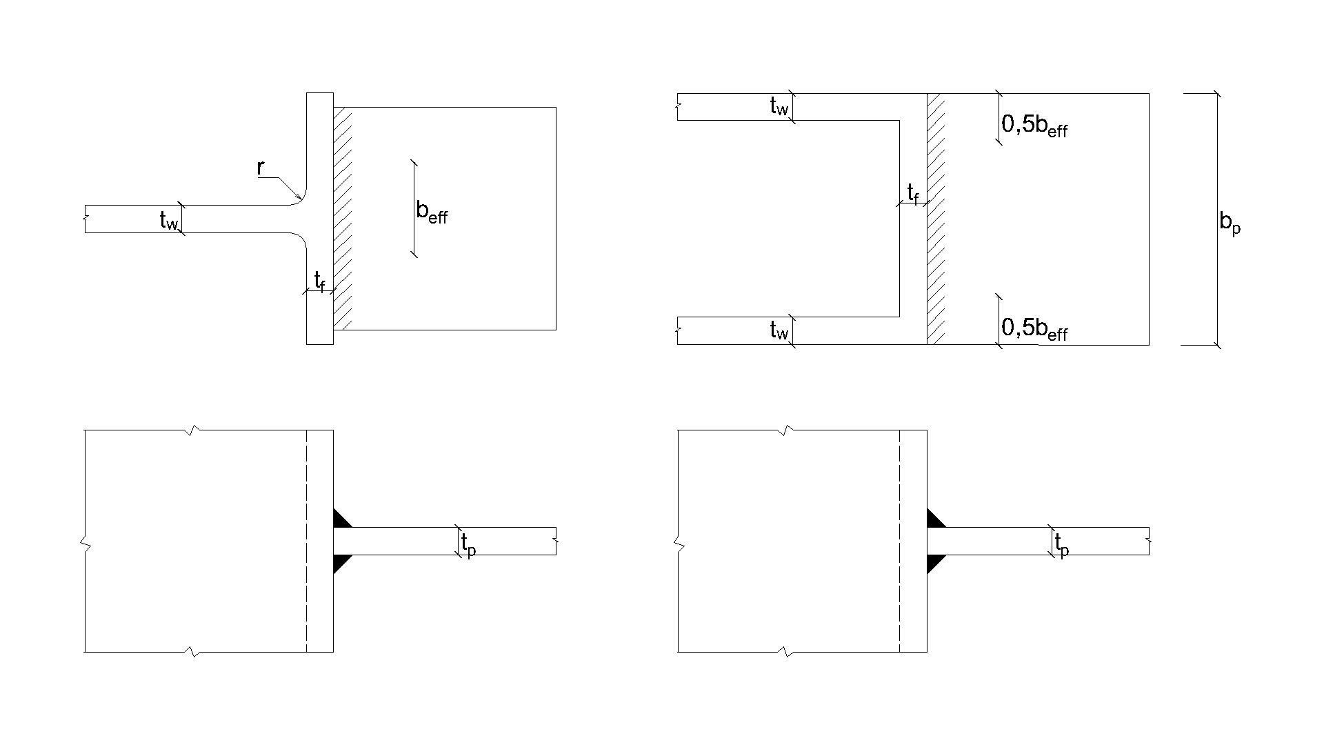
\[ \textsf{\textit{\footnotesize{Fig. 4.5.1 Larghezza efficace di un giunto non irrigidito (Fig. 4.8 in EN 1993-1-8:2005)}}}\]
Modello numerico
La componente saldatura nel CBFEM è descritta nel Background teorico generale e nel Background teorico EN. Il ramo plastico viene raggiunto in una parte della saldatura e i picchi di tensione vengono ridistribuiti lungo la lunghezza della saldatura.
Verifica della resistenza
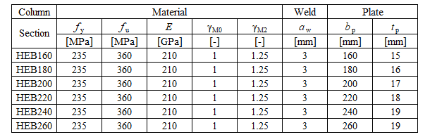
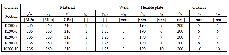
La resistenza di progetto calcolata con CBFEM viene confrontata con i risultati del CM. Viene confrontata solo la resistenza di progetto della saldatura. Una panoramica degli esempi considerati e del materiale è riportata nella Tab. 4.5.1. La geometria dei giunti con le dimensioni è mostrata in Fig. 4.5.2.
\[ \textsf{\textit{\footnotesize{Tab. 4.5.1 Panoramica degli esempi}}}\]
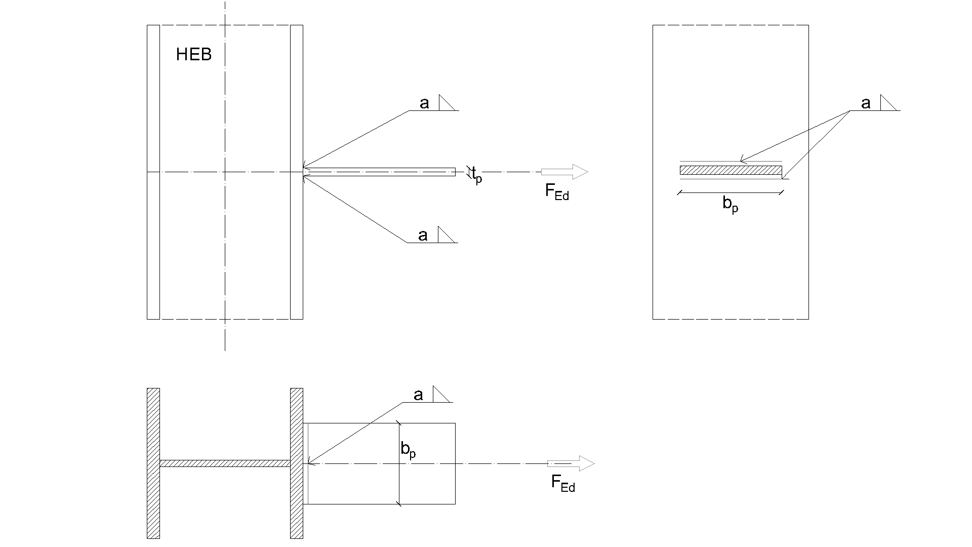
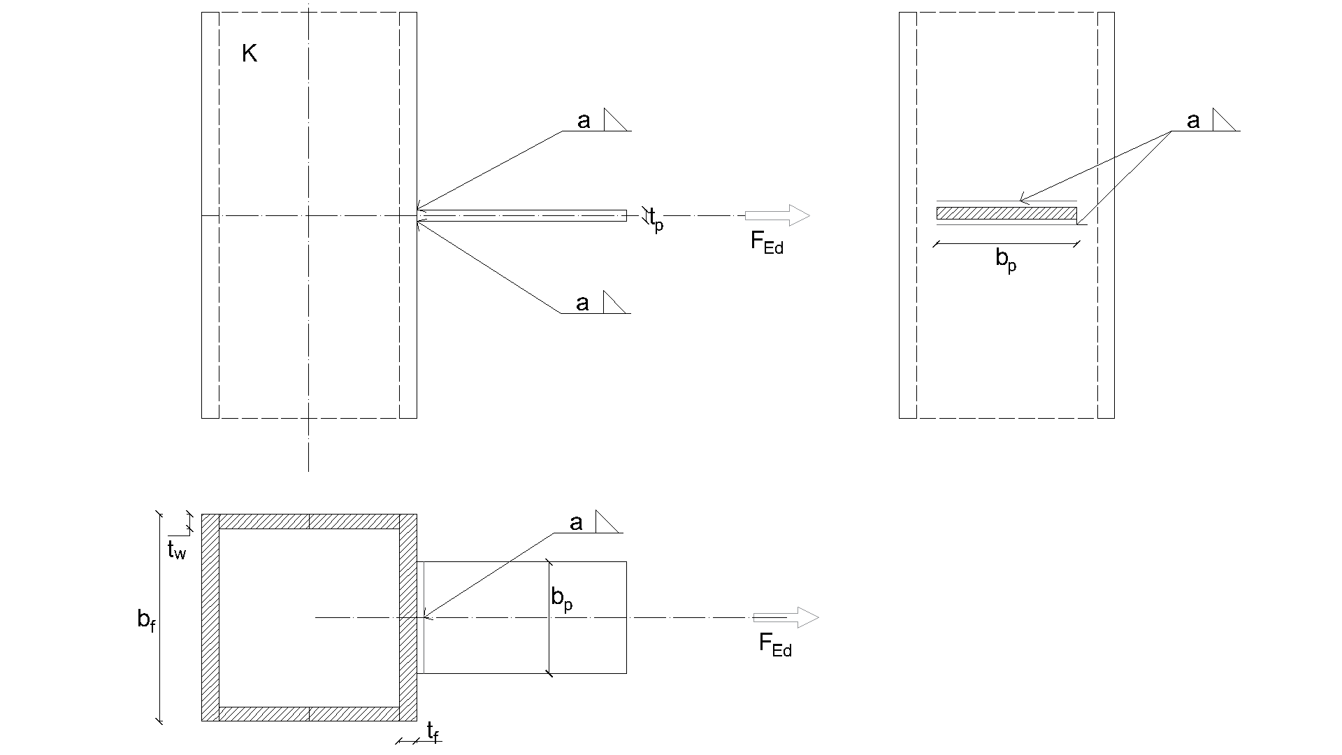
\[ \textsf{\textit{\footnotesize{a) Piastra flessibile su sezione aperta b) Piastra flessibile su sezione cava}}}\]
\[ \textsf{\textit{\footnotesize{Fig. 4.5.2 Geometria e dimensioni del giunto}}}\]
I risultati sono presentati nella Tab. 4.5.2. Lo studio è condotto per due parametri: la larghezza della flangia della sezione HEB e lo spessore dell'anima della sezione cava. La piastra flessibile è caricata a trazione. L'influenza della larghezza della flangia della sezione HEB sulla resistenza di progetto del giunto è mostrata in Fig. 4.5.3. La relazione tra lo spessore dell'anima della sezione cava e la resistenza di progetto del giunto è mostrata in Fig. 4.5.4.
\[ \textsf{\textit{\footnotesize{Tab. 4.5.2 Confronto tra CBFEM e CM}}}\]

I risultati di CBFEM e CM sono confrontati in uno studio di sensibilità. L'influenza della larghezza della flangia della sezione HEB sulla resistenza di progetto del giunto è studiata in Fig. 4.5.3. L'influenza dello spessore dell'anima della sezione cava sulla resistenza di progetto del giunto è presentata in Fig. 4.5.4. Gli studi parametrici mostrano un ottimo accordo dei risultati per tutte le configurazioni di saldatura.
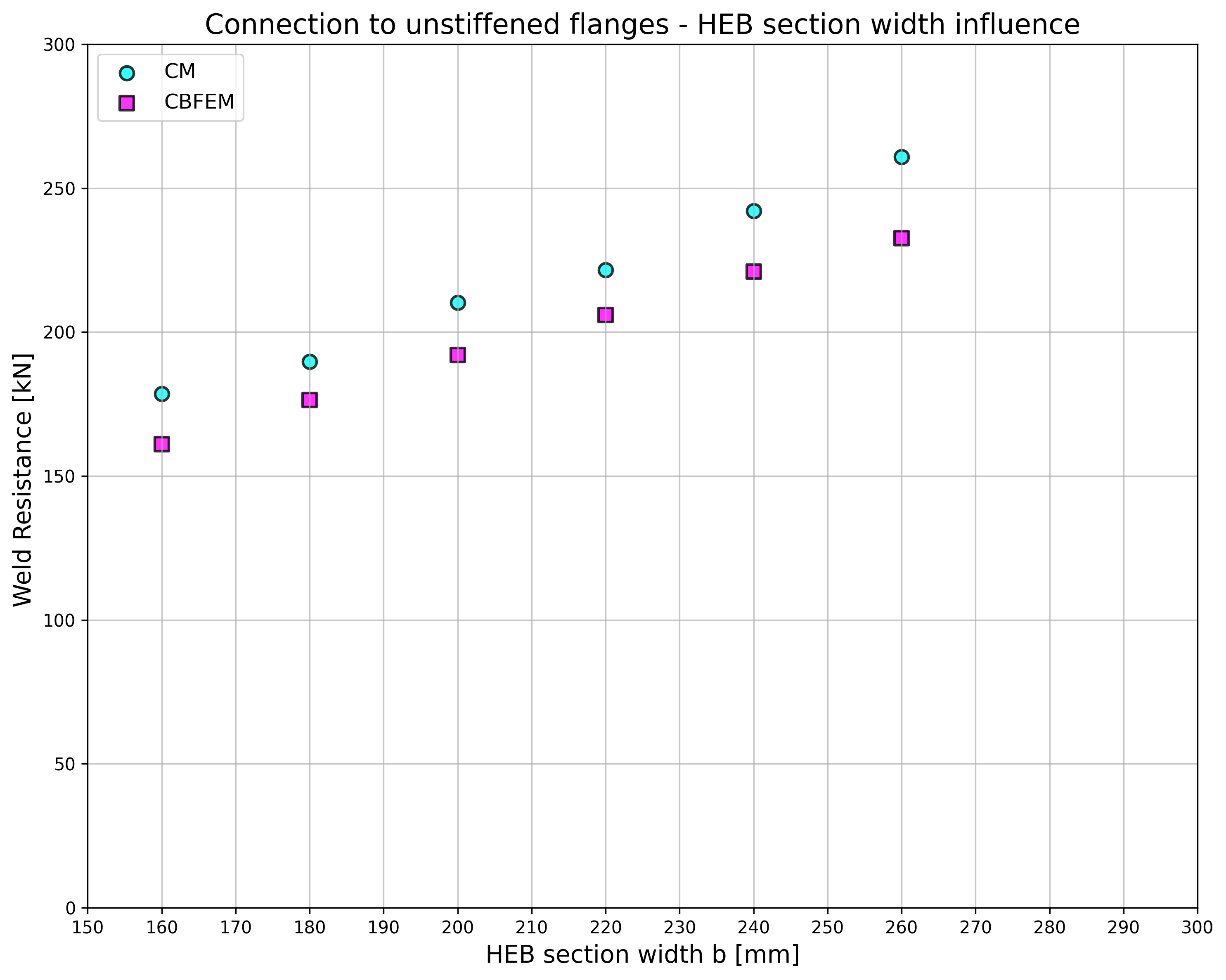
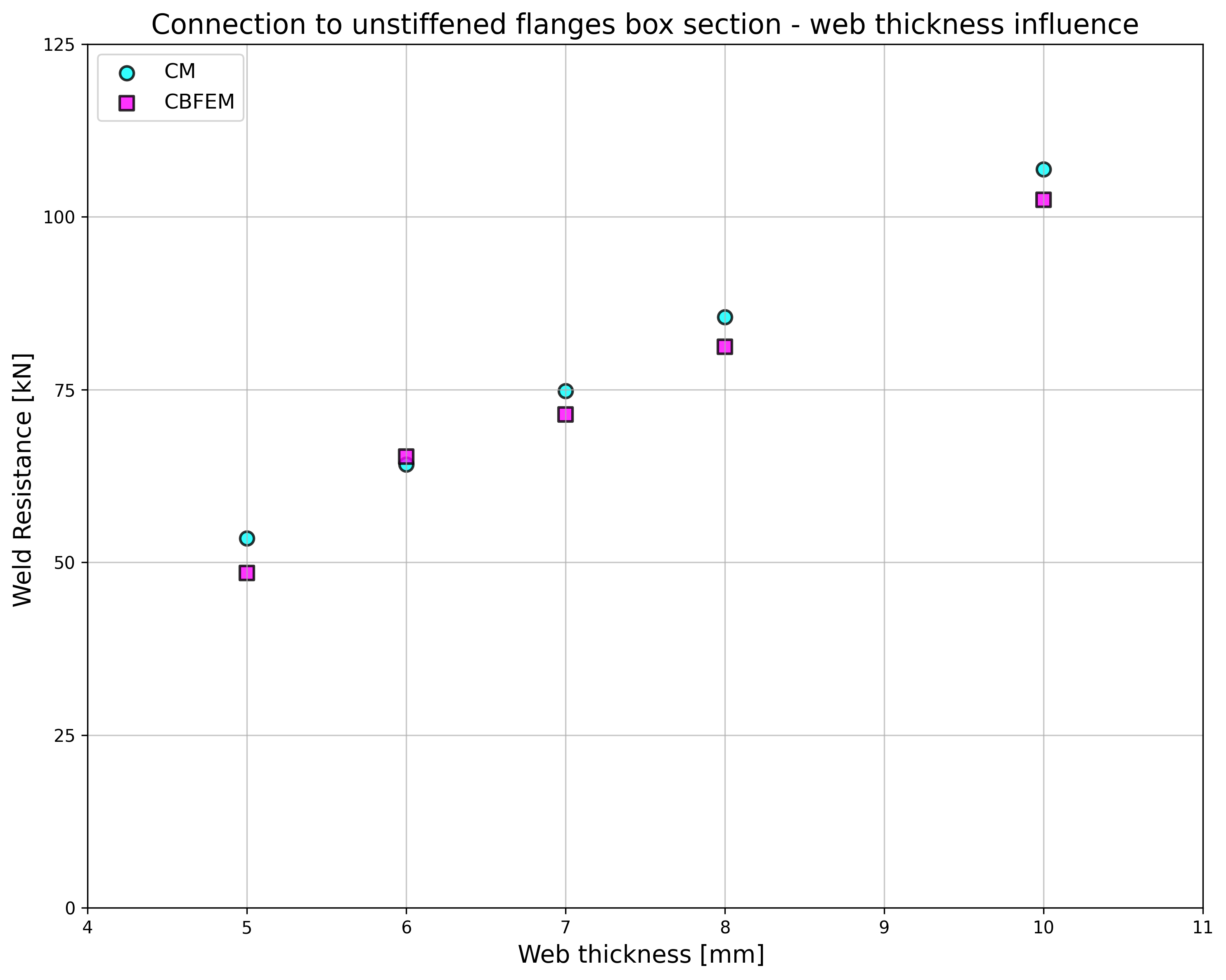
\[ \textsf{\textit{\footnotesize{Fig. 4.5.3 Larghezza della flangia della sezione HEB Fig. 4.5.4 Spessore dell'anima della sezione cava}}}\]
I risultati dello studio di sensibilità sono riassunti in un diagramma che confronta le resistenze di progetto di CBFEM e CM; vedere Fig. 4.5.5 che illustra l'accuratezza del modello CBFEM.
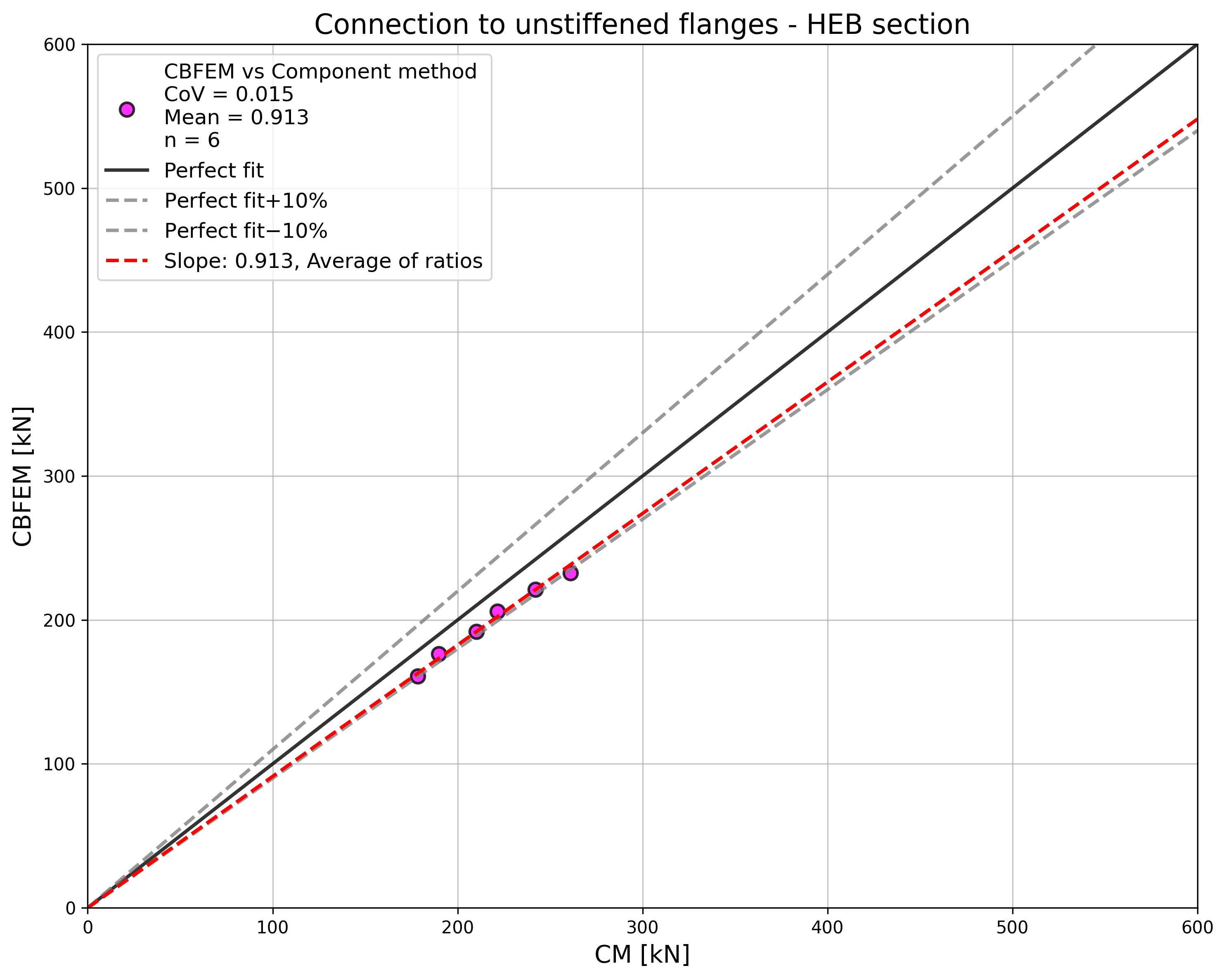
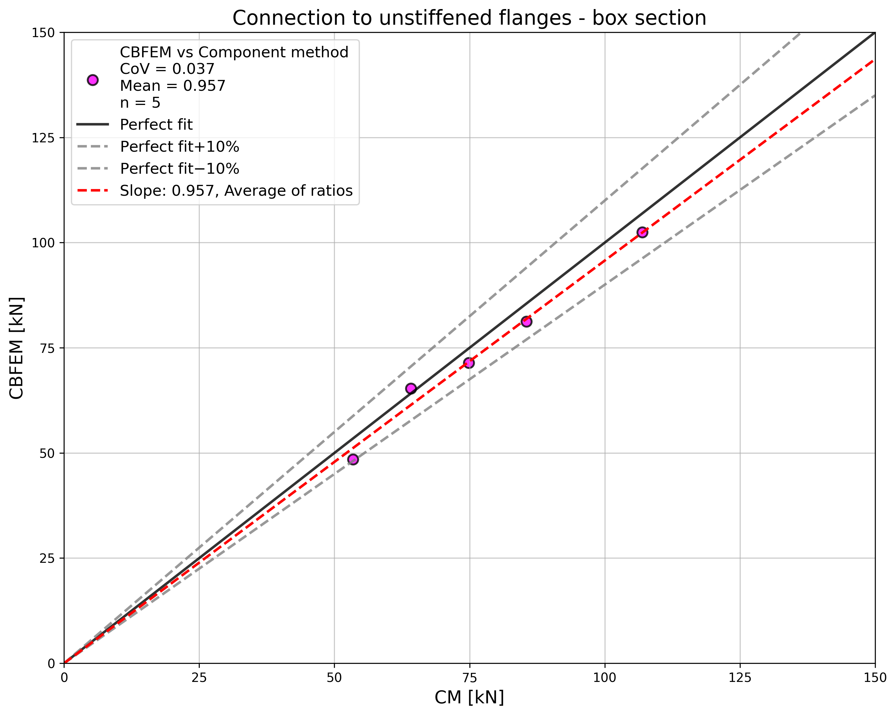
\[ \textsf{\textit{\footnotesize{Fig. 4.5.5 Verifica del CBFEM rispetto al CM}}}\]
L'influenza dello spessore della piastra sulla resistenza di progetto della saldatura è mostrata in Fig. 4.5.6. La sezione trasversale della colonna è HEB 180 con uno spessore della flangia di 14 mm. Una saldatura che collega una piastra più spessa della flangia della colonna ha la stessa resistenza per CM e CBFEM. D'altra parte, la saldatura che collega la piastra alla flangia della colonna di uguale o minore spessore presenta nei modelli numerici una resistenza di progetto inferiore del 20%. Lo spessore della piastra non viene preso in considerazione nei modelli numerici con elementi shell, il che causa la differenza.
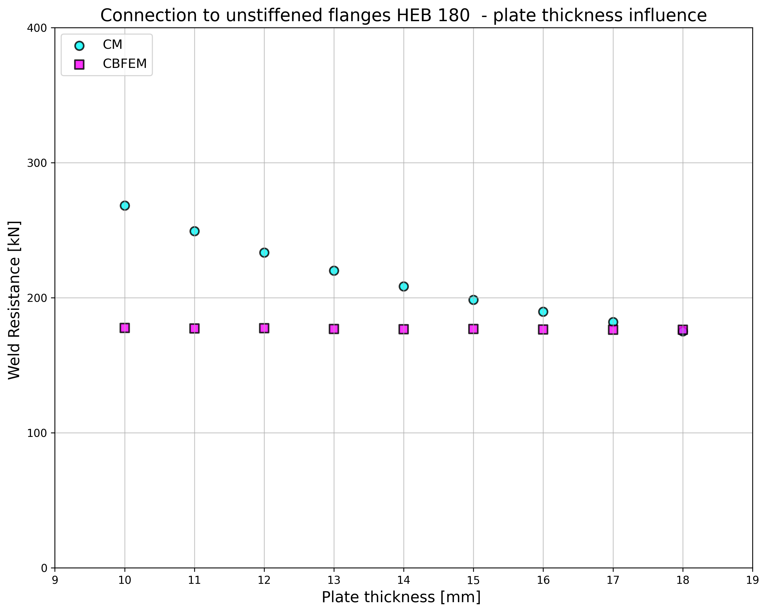
\[ \textsf{\textit{\footnotesize{Fig. 4.5.6 Influenza dello spessore della piastra sulla resistenza del giunto con colonna non irrigidita HEB180}}}\]
Esempio di riferimento
Dati di input
Colonna
• Acciaio S235
• RHS 200/200/5
Piastra flessibile
• Acciaio S235
• Spessore tp = 17 mm
• Larghezza bp = 190 mm
Saldatura, doppie saldature d'angolo vedere Fig. 4.5.7
• Spessore di gola aw = 5 mm
Risultati
• Resistenza di progetto a trazione NRd = 68 kN
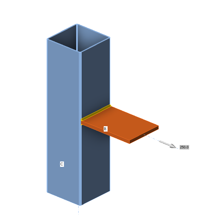
\[ \textsf{\textit{\footnotesize{Fig. 4.5.7 Esempio di riferimento per il collegamento saldato di piastra a colonna non irrigidita}}}\]