Proiectarea structurală a unui nod de cadru din beton (EN)
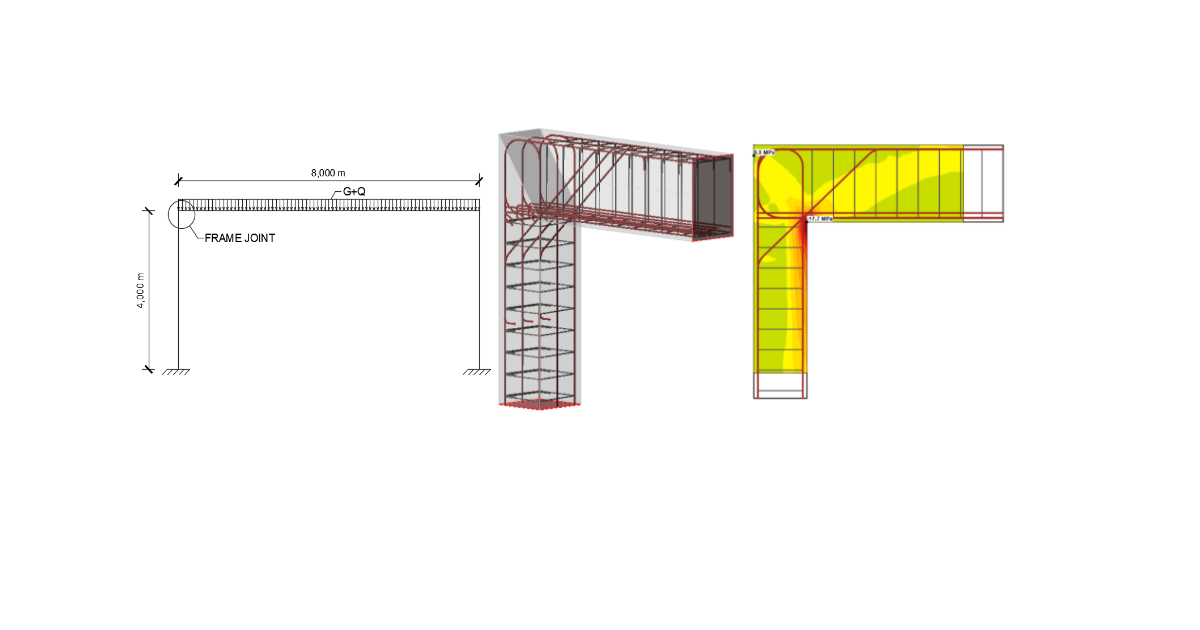
Nodul de cadru analizat va face parte dintr-o structură reală de cadru din beton armat. Cadrul are 4 m înălțime, deschiderea este de 8 m și ambele stâlpi vor avea reazeme încastrate.
1 Proiect nou
Să lansăm IDEA StatiCa și să selectăm aplicația Detail. Se deschide fereastra Wizard și puteți seta clasa betonului și a armăturii și defini grosimea acoperirii cu beton. Selectați tipul de model 2D, clasa Noduri de cadru și topologia Nod de colț.
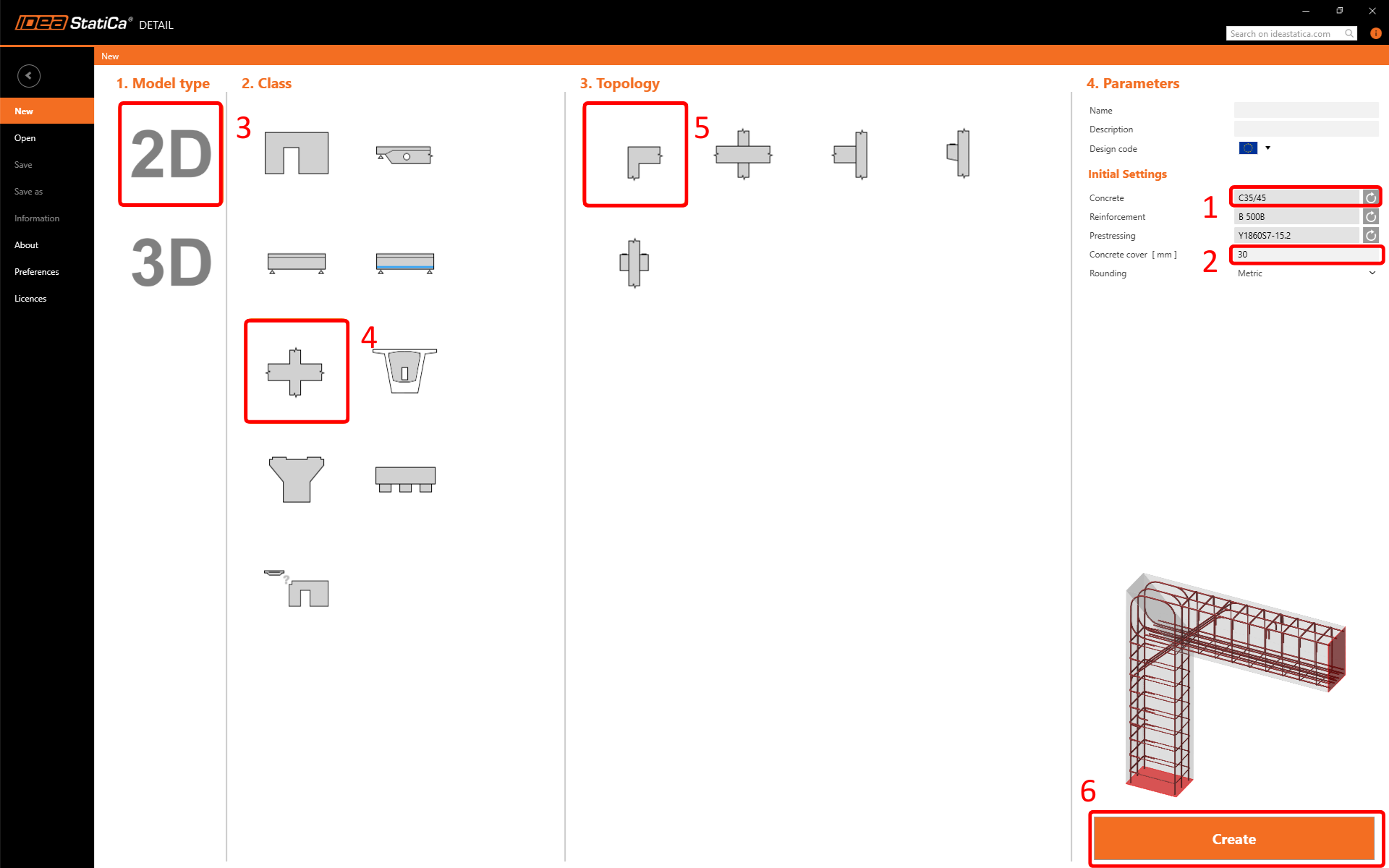
Prin alegerea unui șablon predefinit, software-ul va genera automat geometria, încărcările și armătura.
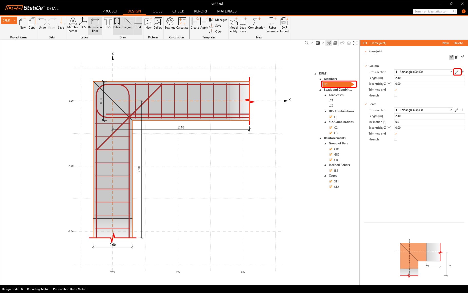
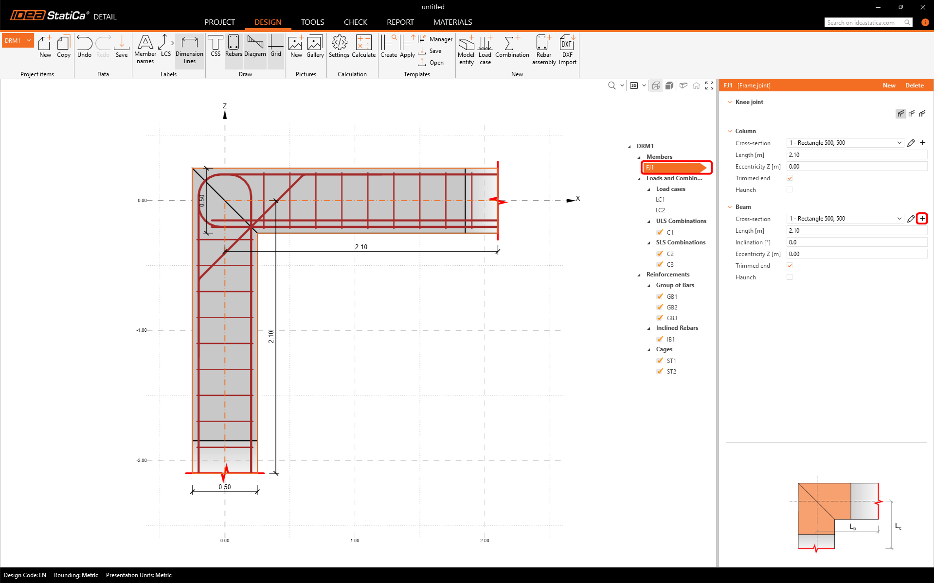
2 Geometrie
Începeți cu modificarea geometriei. Nodul de colț predefinit (Element FJ1) este compus dintr-un Stâlp și o Grindă. Modificați secțiunea transversală a stâlpului făcând clic pe Editare parametri.
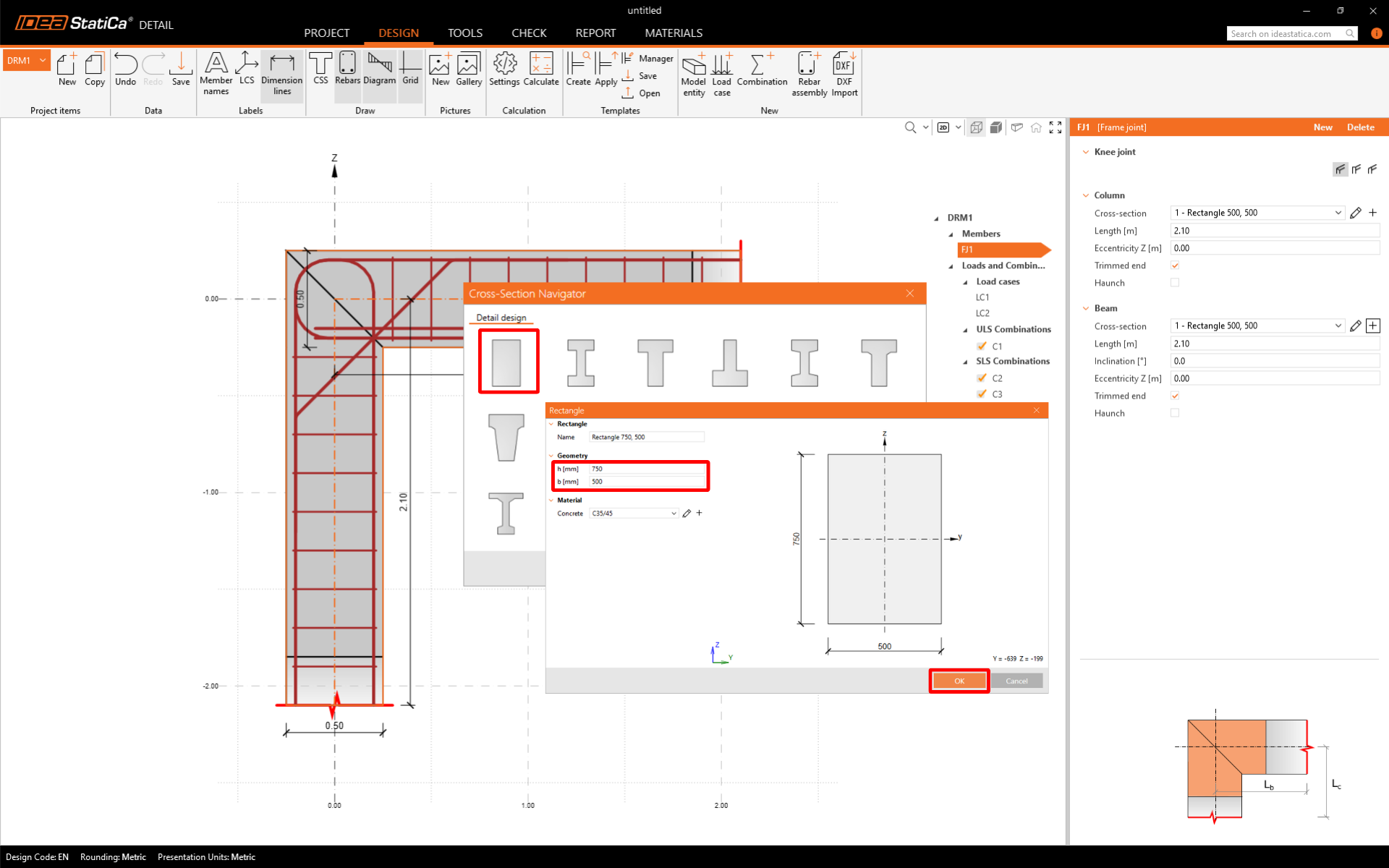
Să modificăm dimensiunile secțiunii transversale.
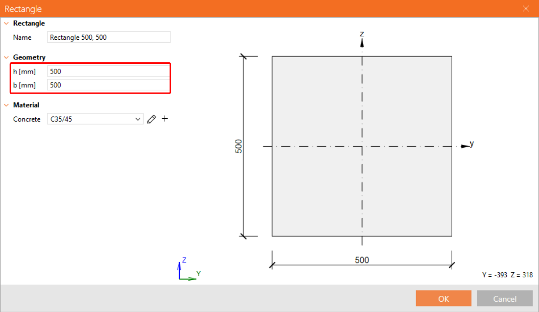
Apoi adăugați o nouă secțiune transversală pentru grindă.
Din nou, modificați dimensiunile.
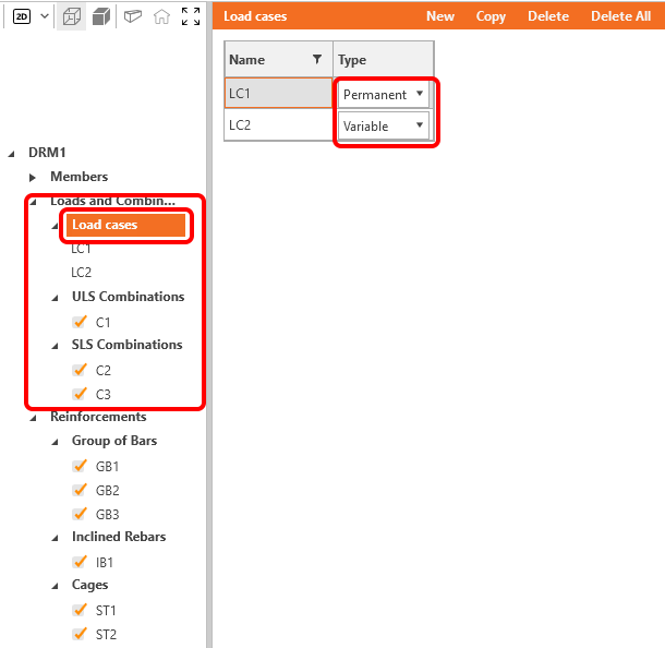
3 Încărcări
În meniul arborescent, continuați cu definirea încărcărilor. Două cazuri de încărcare și trei combinații neliniare au fost adăugate automat de software. Aveți nevoie de două cazuri de încărcare pentru a distinge între încărcările permanente și cele variabile și de trei combinații pentru a acoperi verificările SLU și SLS.
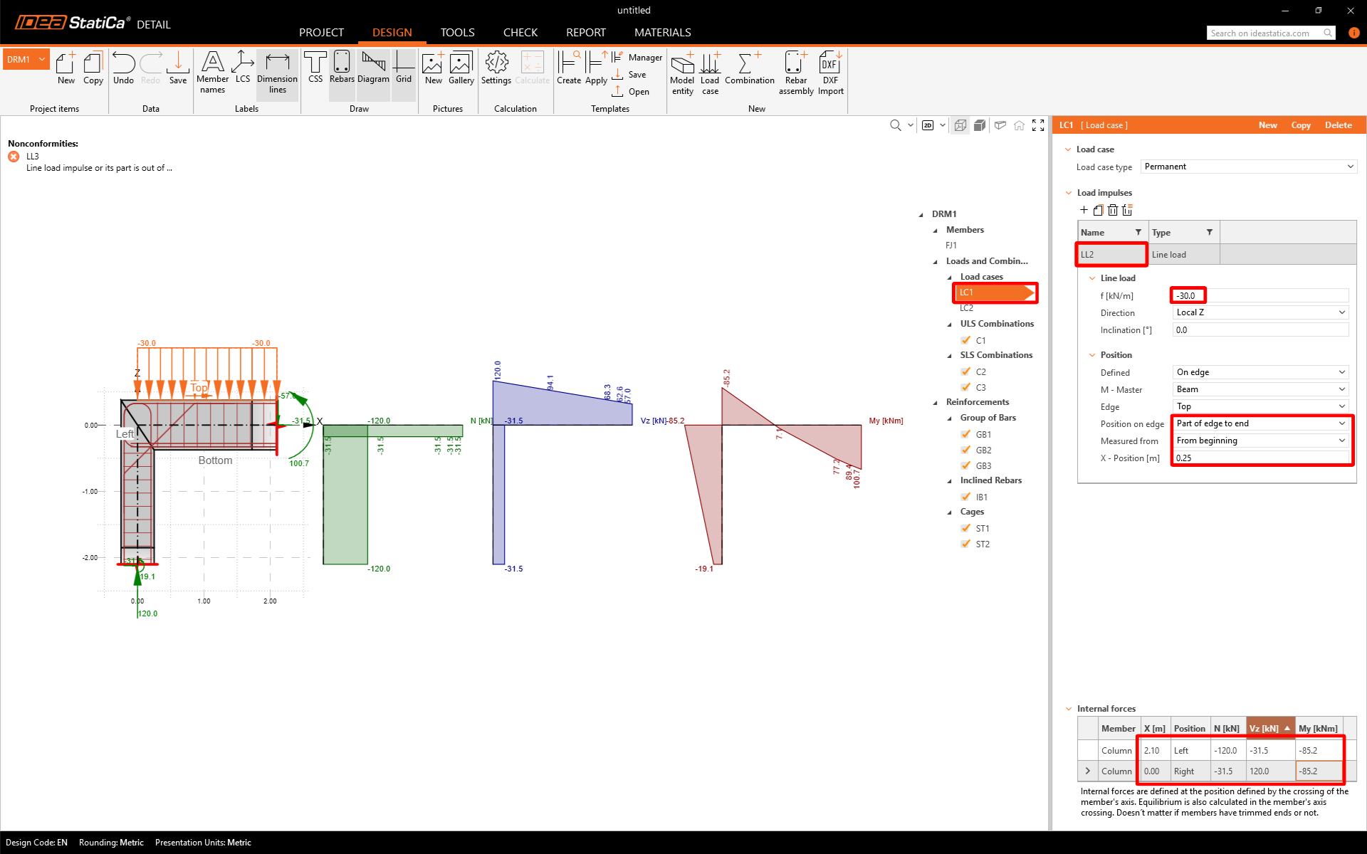
Să modificăm cazul de încărcare LC1 pentru efectele permanente. Mai întâi, eliminați încărcarea liniară de pe stâlp.
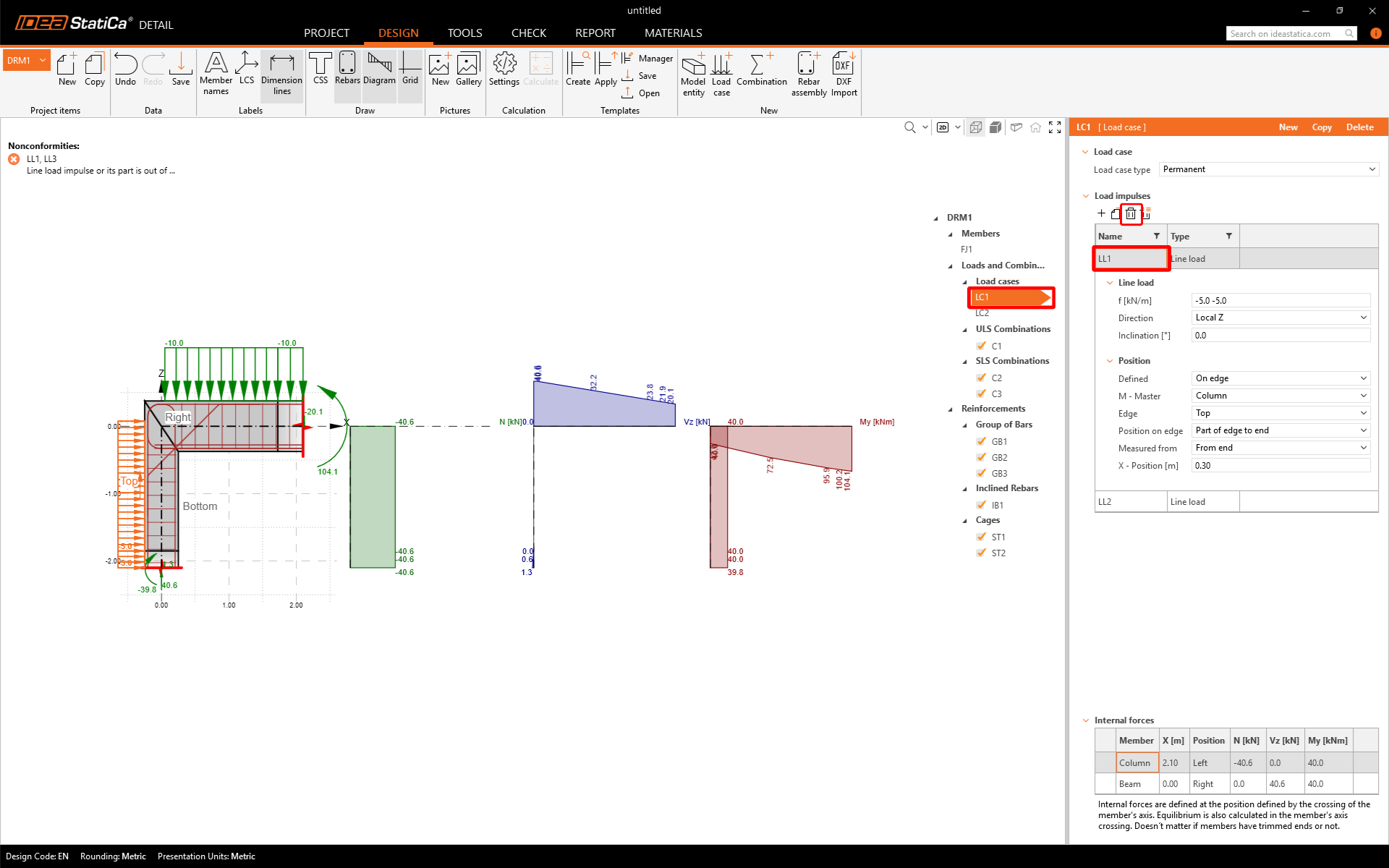
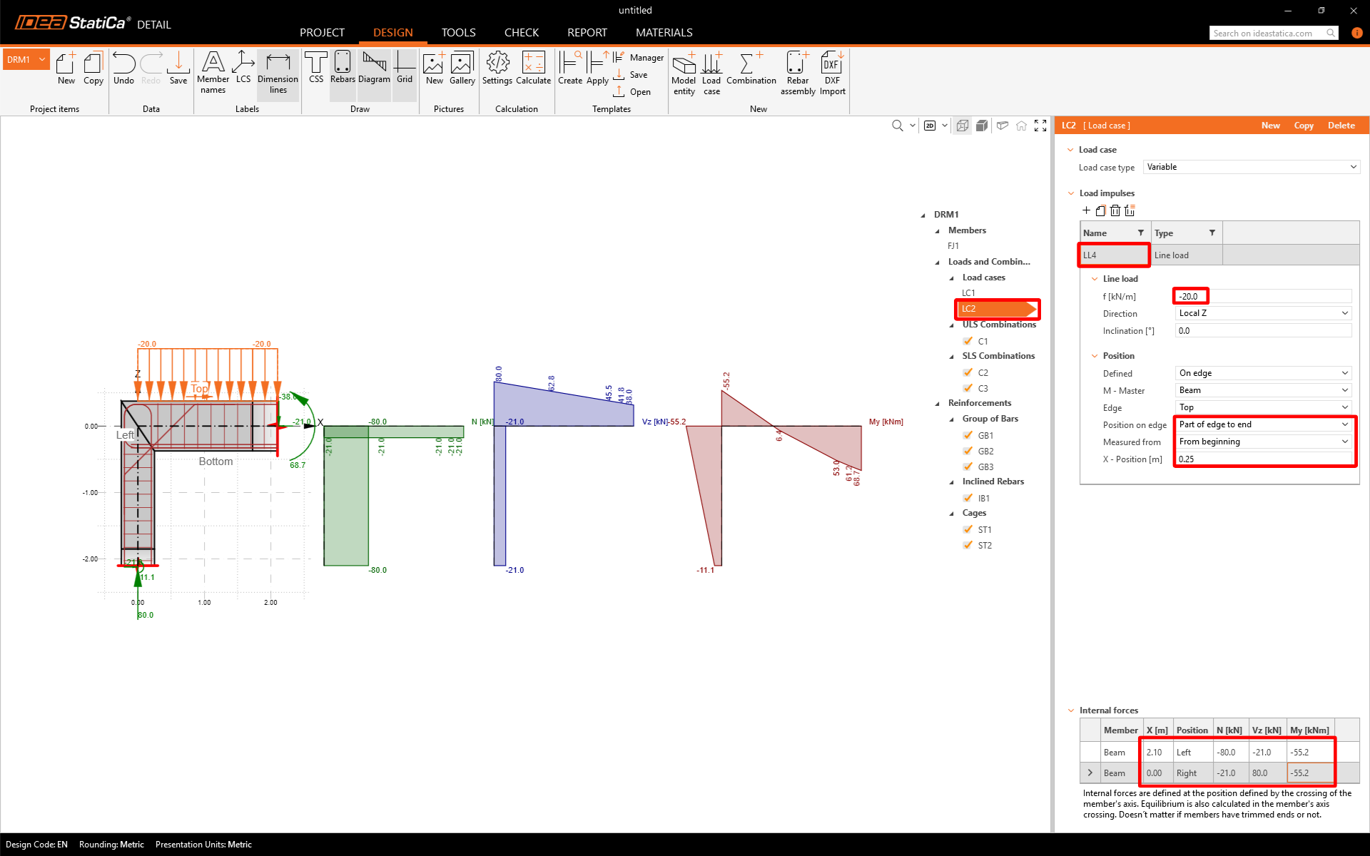
Apoi puteți modifica intensitatea încărcării liniare pe grindă. În tabelul din partea de jos, setați valorile Eforturilor interioare care sunt aplicate secțiunii transversale plasate la intersecția stâlpului cu grinda. Puteți obține aceste eforturi interioare prin modelarea și calculul întregului cadru cu încărcarea liniară corespunzătoare (30 kN/m pentru LC1 și 20 kN/m pentru LC2) în orice software CAE/FEM în câteva minute.
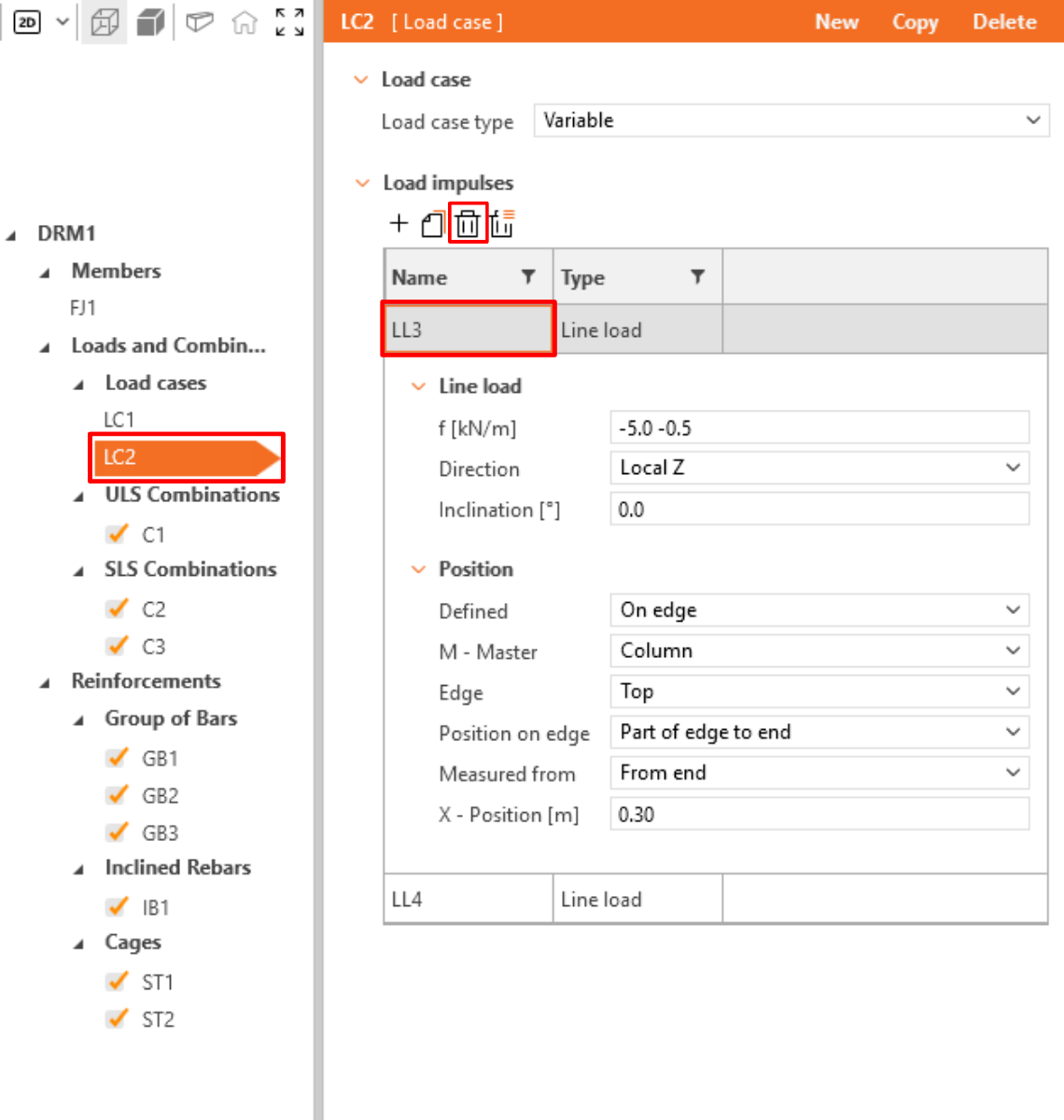
Treceți la cazul de încărcare LC2 și repetați pașii cu valori diferite. Mai întâi ștergeți încărcarea liniară LL3.
Apoi ajustați încărcarea liniară LL4 și eforturile interioare.
Făcând clic pe SLU sau Combinații SLS, puteți selecta tipul de combinație și ajusta coeficienții parțiali pentru fiecare combinație neliniară.
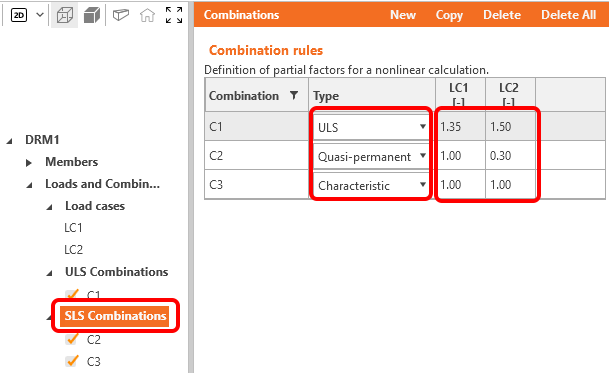
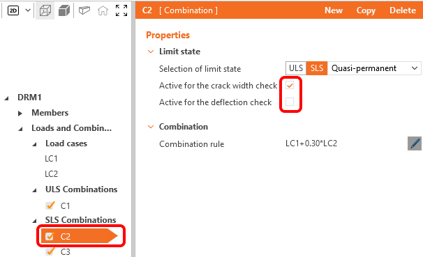
Pentru fiecare Combinație SLS puteți selecta ce verificări conform codului vor fi efectuate.
4 Armătură
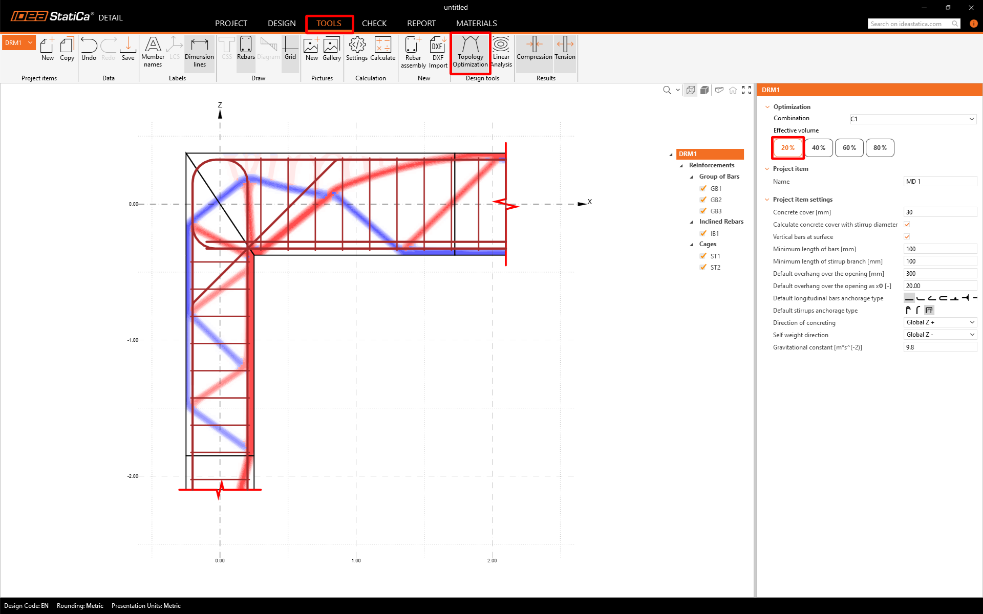
Odată ce încărcarea a fost definită, puteți trece la proiectarea armăturii. Înainte de a proiecta una, puteți încerca să rulați instrumentul Optimizare Topologică pentru a vedea cum ar trebui să arate dispunerea optimă a armăturii dacă doriți să utilizați volumul efectiv selectat al structurii.
Pentru un volum efectiv de 20%, structura arată astfel (liniile roșii reprezintă compresiunea, iar liniile albastre reprezintă întinderea). Puteți comuta între volumele efective în fereastra din dreapta.
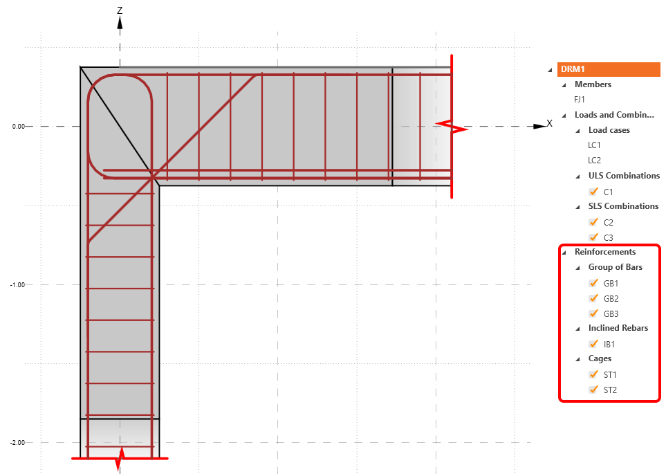
Continuați cu definirea Armăturilor. Veți edita elementele create de șablon.
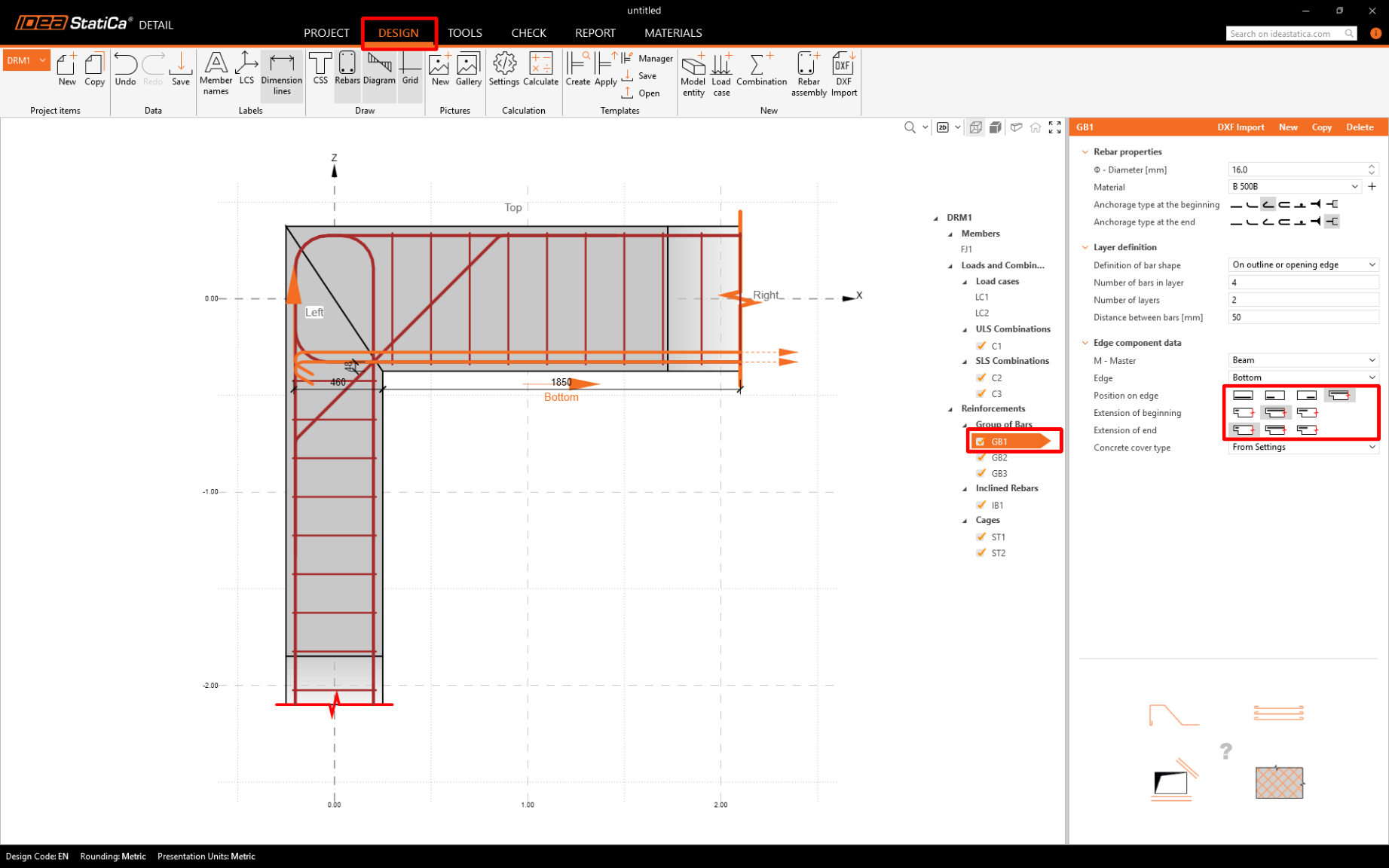
Modificați grupul GB1, barele vor fi prelungite până la marginea stângă:
5 Calcul și Verificare
Porniți analiza făcând clic pe Calculați în panglică. Modelul de analiză este generat automat și calculele sunt efectuate. Treceți la fila Verificare. Acum puteți vedea Rezumatul rezultatelor. În partea stângă sus puteți vedea toate SLU și SLS cu gradul lor de utilizare procentual.
În fereastra din dreapta puteți vedea un tabel cu rezultate mai detaliate pentru combinațiile de încărcare selectate.
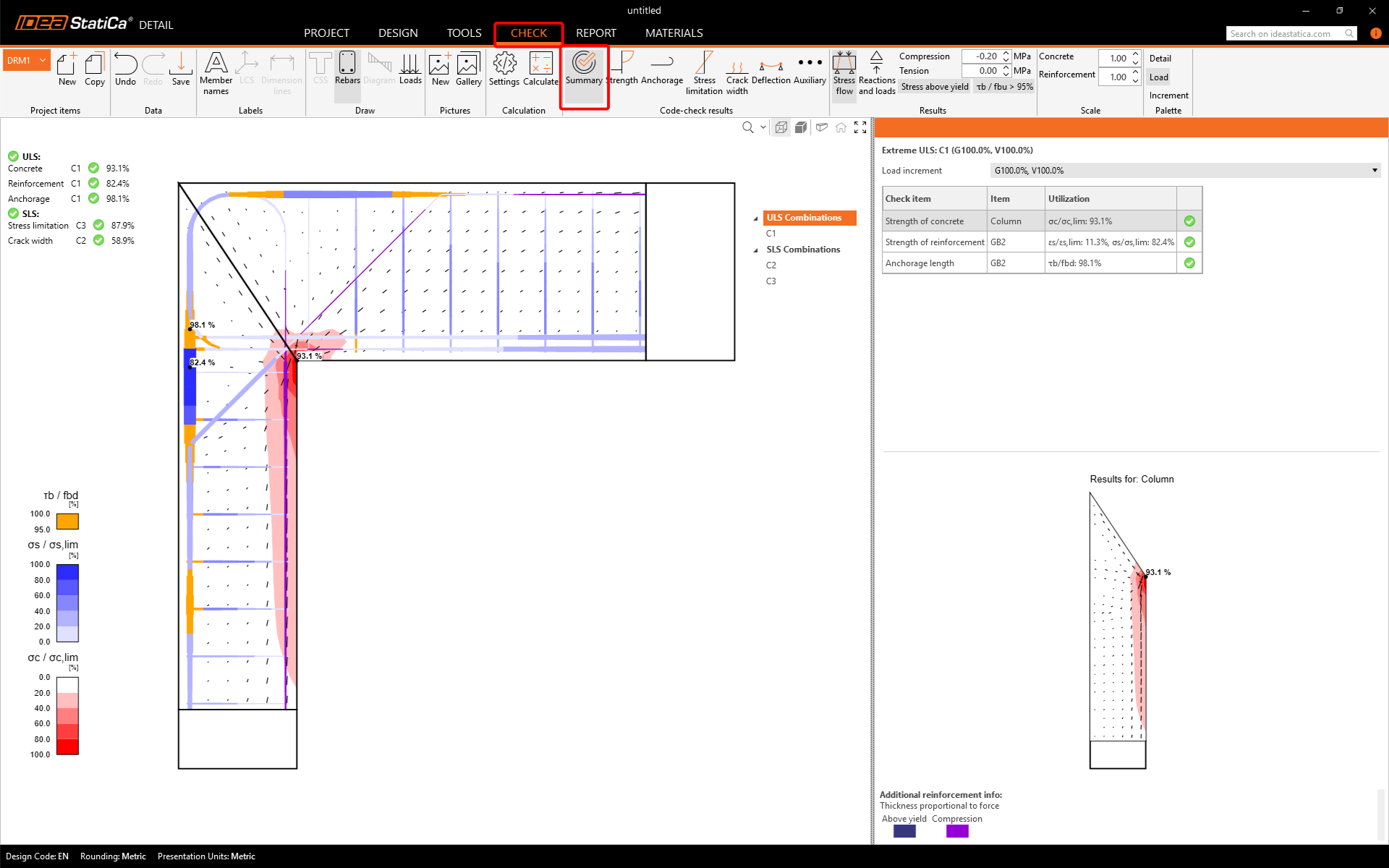
Puteți observa, de asemenea, linia Increment. Valorile P100%, V100% indică faptul că calculul s-a finalizat cu succes și toate încărcările permanente și variabile au fost aplicate pe structură.
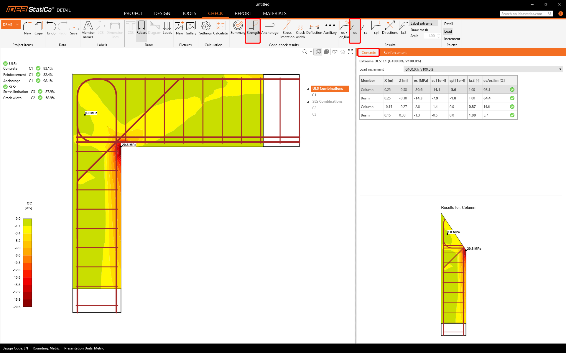
Pentru a deschide rezultatele detaliate ale SLU, faceți clic pe pictograma Rezistență. Așa cum s-a menționat mai sus în tabel, combinația C1 a fost utilizată pentru verificarea SLU.
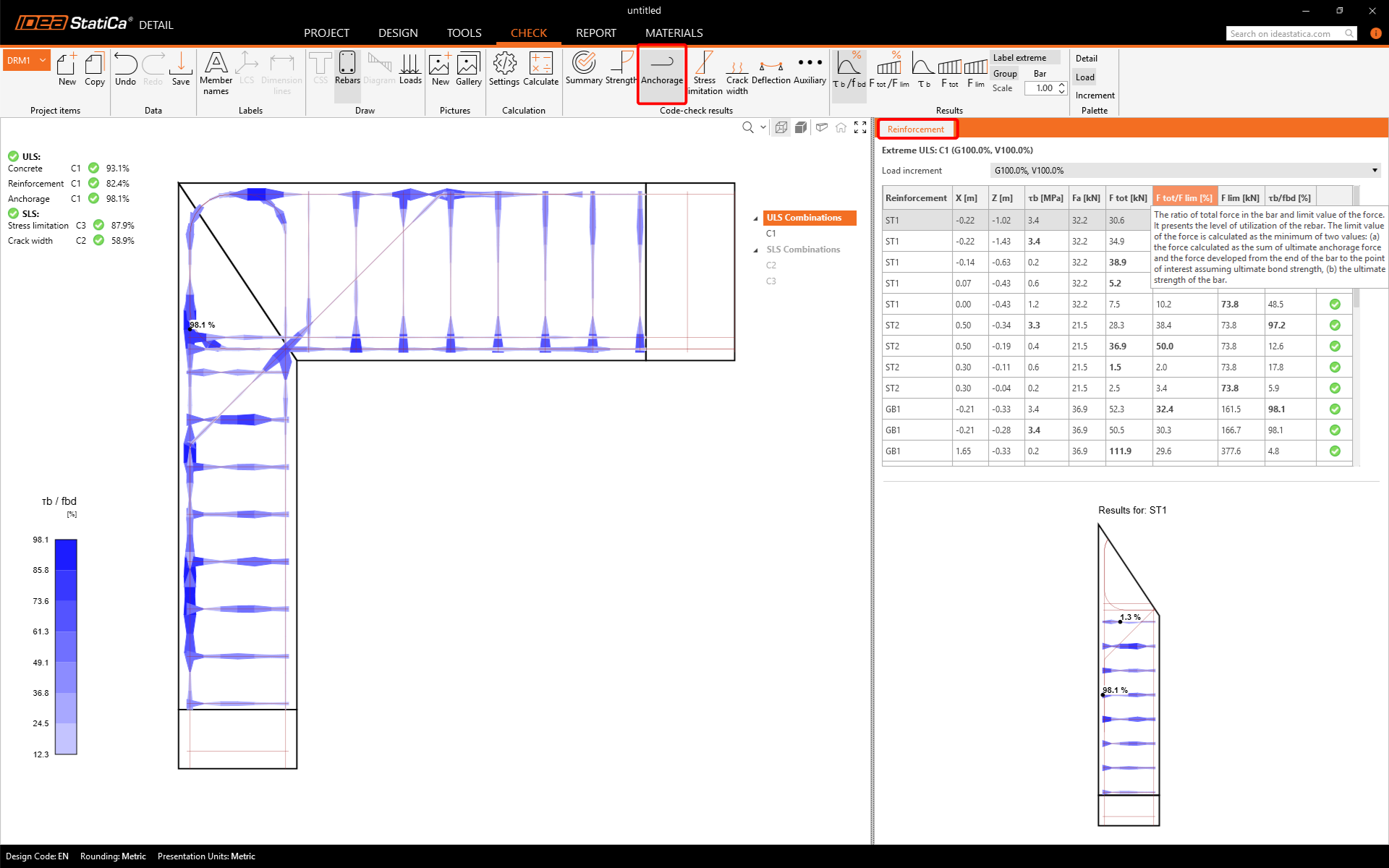
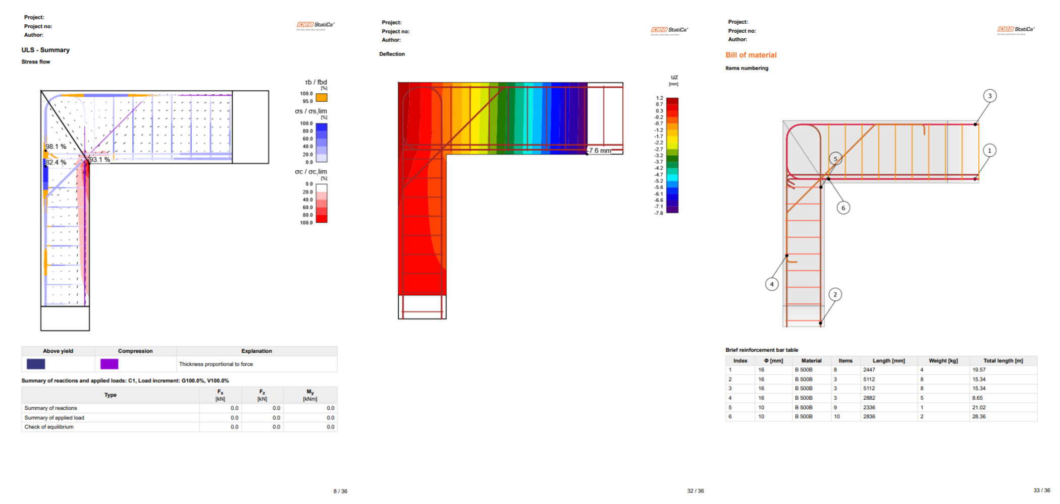
Folosind pictogramele din panglica de sus, puteți afișa toate verificările conform codului. În Rezumat, sunt prezentate principalele rezultate pentru SLU/SLS. Faceți clic pe Ancoraj pentru a afișa gradul de utilizare al aderenței dintre beton și armătură (cu punctul cel mai critic marcat în figură).
Puteți afișa rezultatele verificărilor SLS conform codului (Limitarea tensiunilor, Lățimea fisurilor și Deformația) într-un mod similar.
6 Raport
În final, mergem la fila Raport. IDEA StatiCa oferă un raport complet personalizabil pentru tipărire sau salvare într-un format editabil.
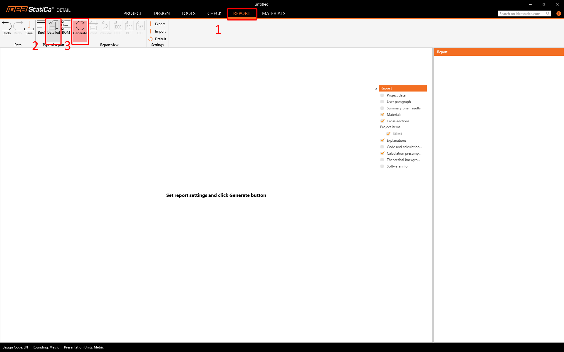
Ați proiectat, optimizat și efectuat verificarea conform codului a unui nod de cadru conform Eurocodului.