Stâlp armat cu consolă (EN)
1 Pornirea unui proiect nou
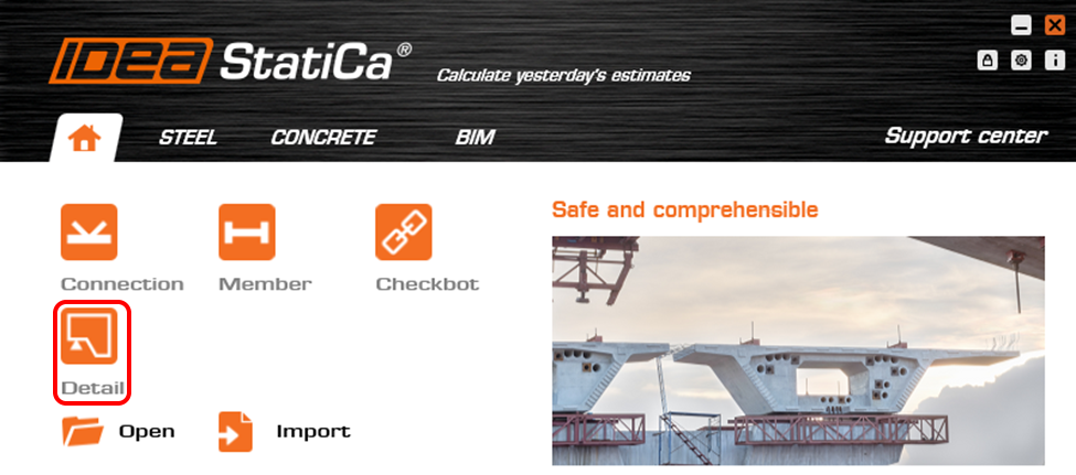
Să lansăm aplicația IDEA StatiCa Detail (descărcați cea mai nouă versiune). În fereastra principală a IDEA StatiCa, deschideți aplicația Detail pentru a defini un proiect nou.
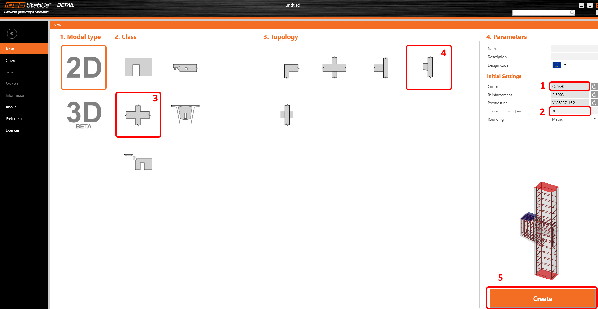
În primul pas, definiți codul de proiectare (alegeți EN), precum și clasa betonului și acoperirea cu beton (utilizați betonul C25/30 și acoperirea de 30 mm). Puteți modifica ulterior alegerea materialului (sau puteți adăuga un altul), însă codul de proiectare poate fi ales doar în acest prim pas al proiectului.
Puteți găsi apoi forma dorită a detaliului printre șabloane. Pentru proiectarea consolei, selectați clasa Îmbinări de cadru și topologia Stâlp cu consolă. Dacă nu găsiți un șablon potrivit, puteți începe cu un proiect gol.
2 Geometrie
Aplicația Detail se va deschide cu fila Proiectare selectată automat. Puteți configura modelul editând elementele din meniul arbore unde puteți modifica elementele, dispozitivele de transfer, încărcările și armăturile. Alternativ, puteți defini elemente noi folosind comenzile din bara de instrumente superioară. Dacă doriți să cunoașteți mai bine mediul aplicației, consultați următorul articol - Interfața generală în aplicația Detail.
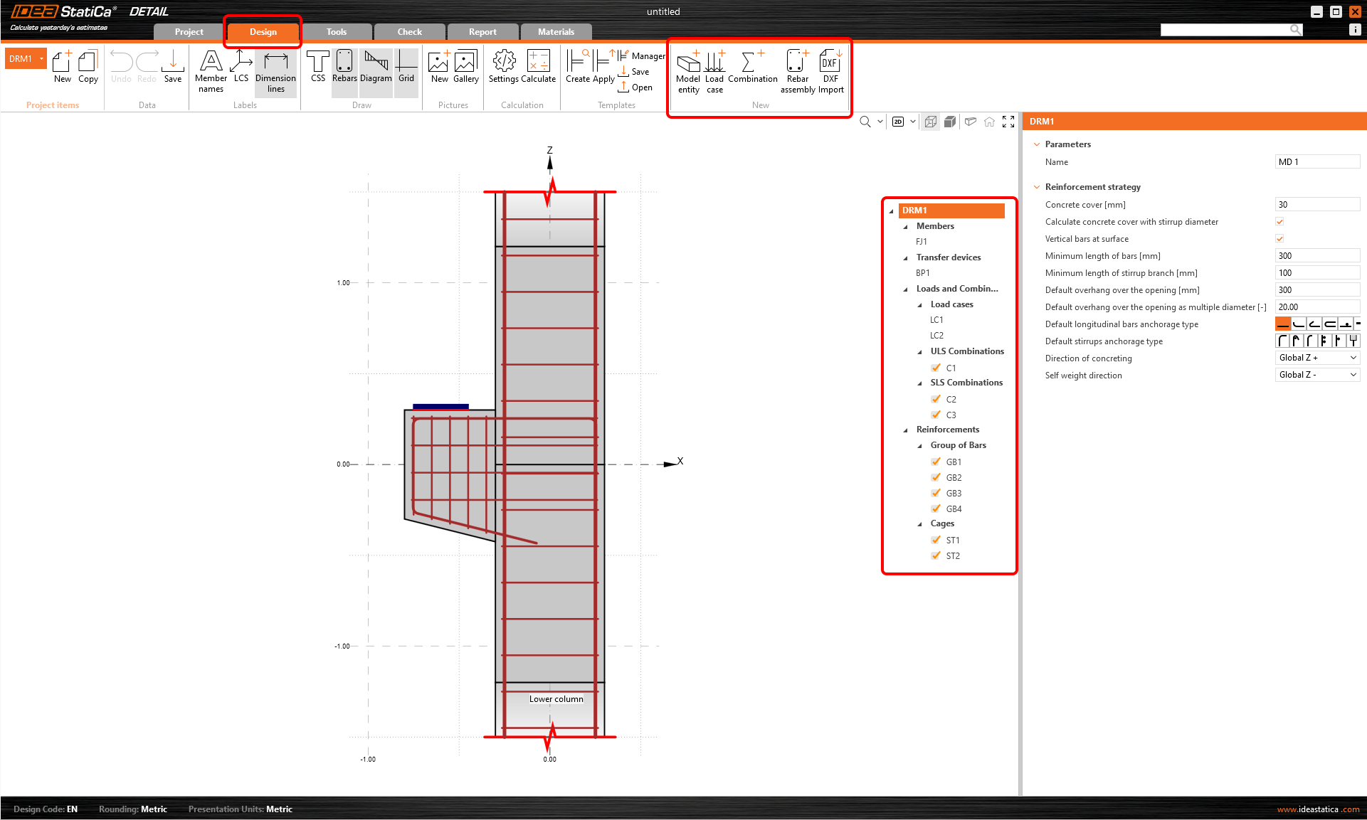
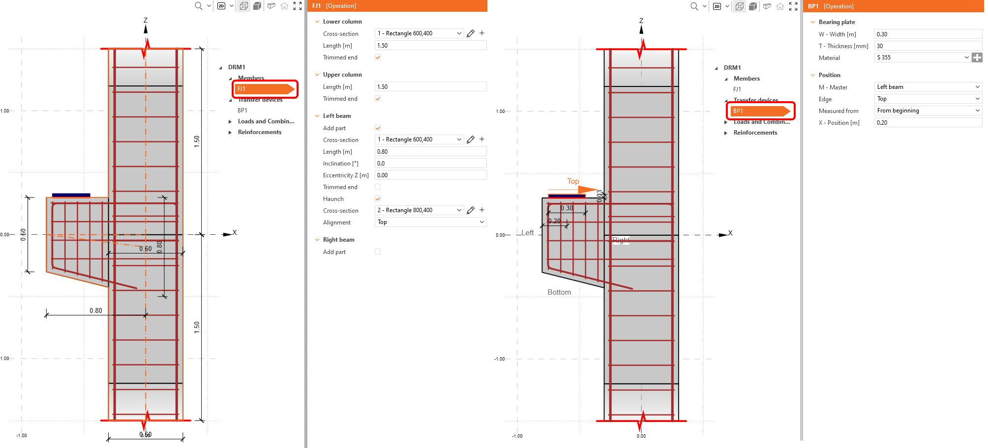
Vom începe cu secțiunile Elemente și Dispozitive de transfer, unde puteți ajusta elementele geometrice (pereți, grinzi și goluri), reazeme și dispozitive de transfer al încărcărilor (cum ar fi placa de reazem, reazem de suprafață etc.).
În acest caz, două elemente au fost deja create de șablon: îmbinarea de cadru FJ1 și o placă de reazem BP1.
- Citiți mai multe despre tipurile de geometrie în Tipuri de geometrie în Detail
- Citiți mai multe despre reazeme în Tipuri de reazeme în IDEA StatiCa Detail
3 Încărcări și Combinații
A treia secțiune este dedicată definirii Încărcărilor și Combinațiilor. Două cazuri de încărcare (LC1 și LC2) și trei combinații (C1, C2 și C3) au fost deja adăugate automat.
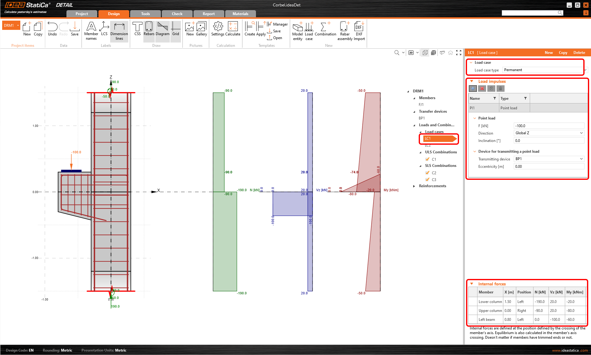
Să începem cu primul caz de încărcare. Faceți clic pe LC1 în meniul arbore. În fereastra de proprietăți din dreapta puteți defini tot ce ține de cazul de încărcare.
Mai întâi, puteți specifica Tipul cazului de încărcare. Pentru a putea distinge între efectele pe termen scurt și cele pe termen lung, este necesar să setați corect tipurile de cazuri de încărcare Permanentă și Variabilă. Setările influențează semnificativ interpretarea verificărilor SLU și SLS.
Apoi puteți continua cu Impulsurile de încărcare, unde puteți seta încărcările exterioare, cum ar fi încărcări concentrate, încărcări liniare, încărcări de suprafață și greutatea proprie.
Se utilizează capete tăiate. De aceea trebuie să setăm Forțele interioare pe elementele individuale și să atingem echilibrul la intersecția stâlpului cu consola.
Puteți configura cazul de încărcare LC2 în mod similar. LC2 va reprezenta încărcările variabile.
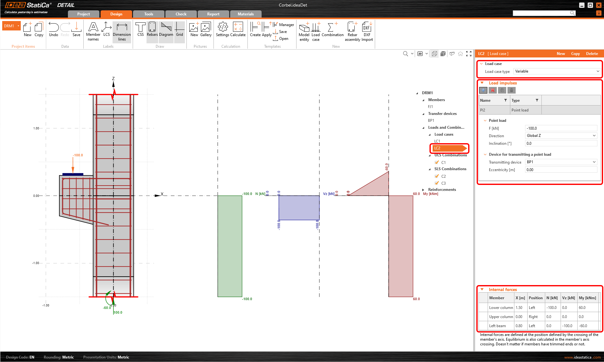
În fereastra principală, puteți verifica dacă forțele interioare corespund forțelor interioare din modelul global.
- Citiți mai multe despre Forțele interioare și echilibrul în Detail
- Citiți mai multe despre Impulsurile de încărcare în Detail
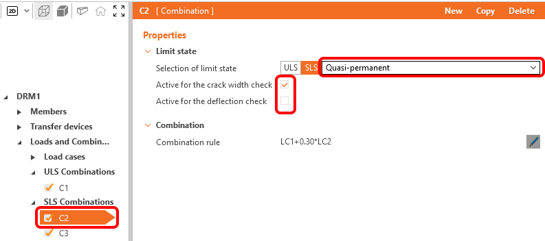
Pentru fiecare combinație puteți selecta starea limită corespunzătoare, SLU sau SLS. Pentru a modifica regulile de combinare, faceți clic pe pictograma creion și setați coeficienții individuali. Observați casetele de selectare bifate pentru combinațiile de încărcări. Calculele vor fi efectuate doar pentru elementele bifate, iar prin excluderea unor combinații puteți accelera calculul.
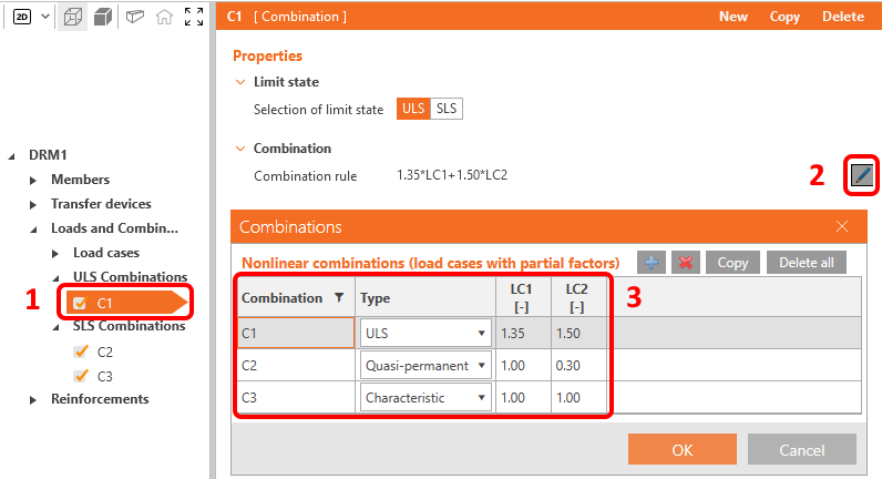
Sunt disponibile trei tipuri de combinații SLS: caracteristică, frecventă și cvasipermanentă, iar utilizatorul poate selecta ce verificări SLS vor fi efectuate pentru fiecare combinație.
4 Armătură
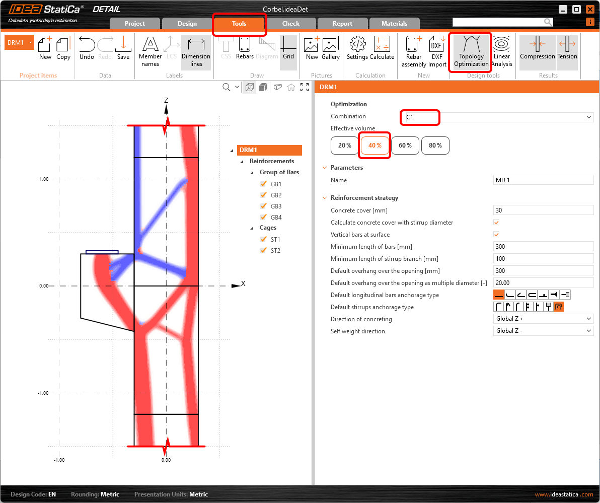
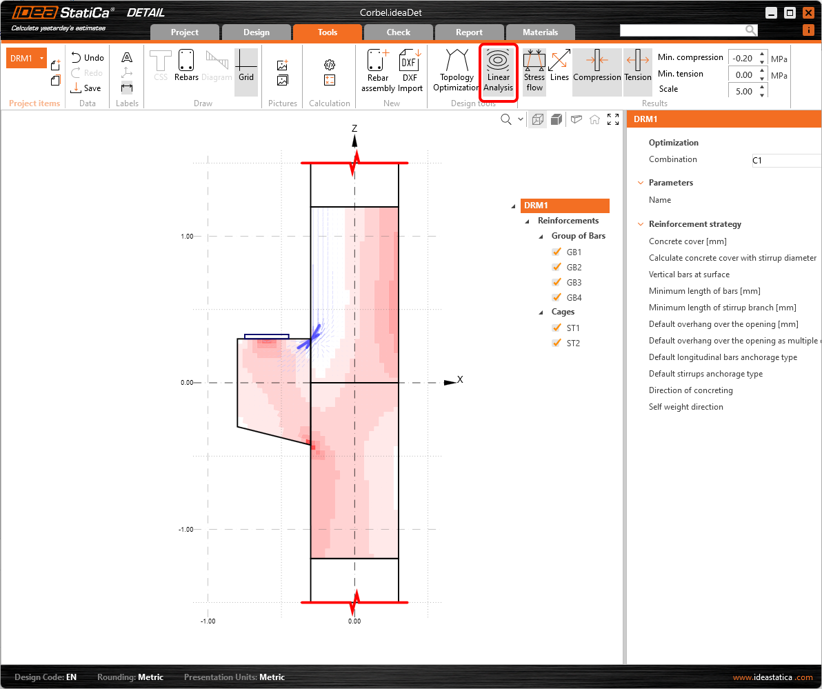
Următorul pas este armarea modelului. Vom edita Armăturile din șablon, dar mai întâi putem trece la fila Instrumente și să analizăm Optimizarea topologică din Instrumente de proiectare, care vă ajută să proiectați armătura. Alternativ, puteți utiliza o Analiză liniară mai tradițională pentru a obține indicii pentru proiectarea armăturii.
- Citiți mai multe despre Optimizarea topologică
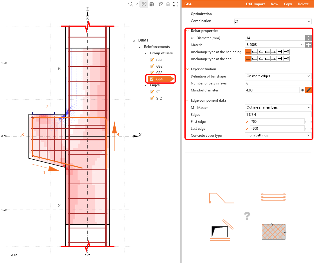
Acum proiectați armătura. Puteți arma detaliul pe baza rezultatelor din instrumentele de proiectare. Pentru aceasta, accesați Armăturile din meniul arbore.
Două grupuri de etrieri și patru grupuri de bare au fost deja adăugate de șablon; le puteți ajusta în funcție de necesități în fereastra de proprietăți.
În final, verificați vizual alinierea armăturii folosind vizualizarea 3D real. Pentru aceasta trebuie să reveniți mai întâi la fila Proiectare.
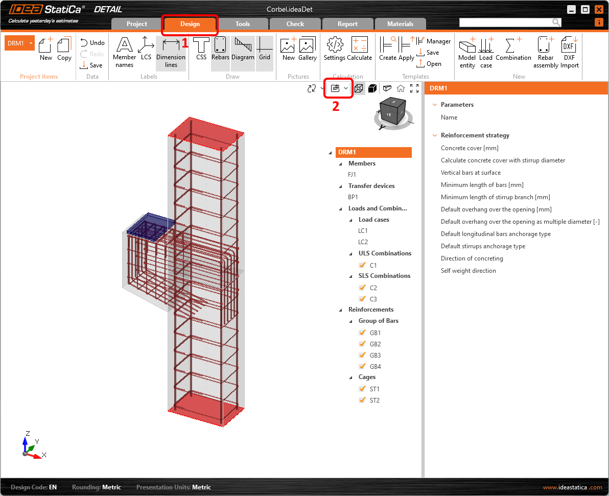
5 Calcul și Verificare
Navigați la Verificare și porniți analiza făcând clic pe butonul Calculați din bara de instrumente.
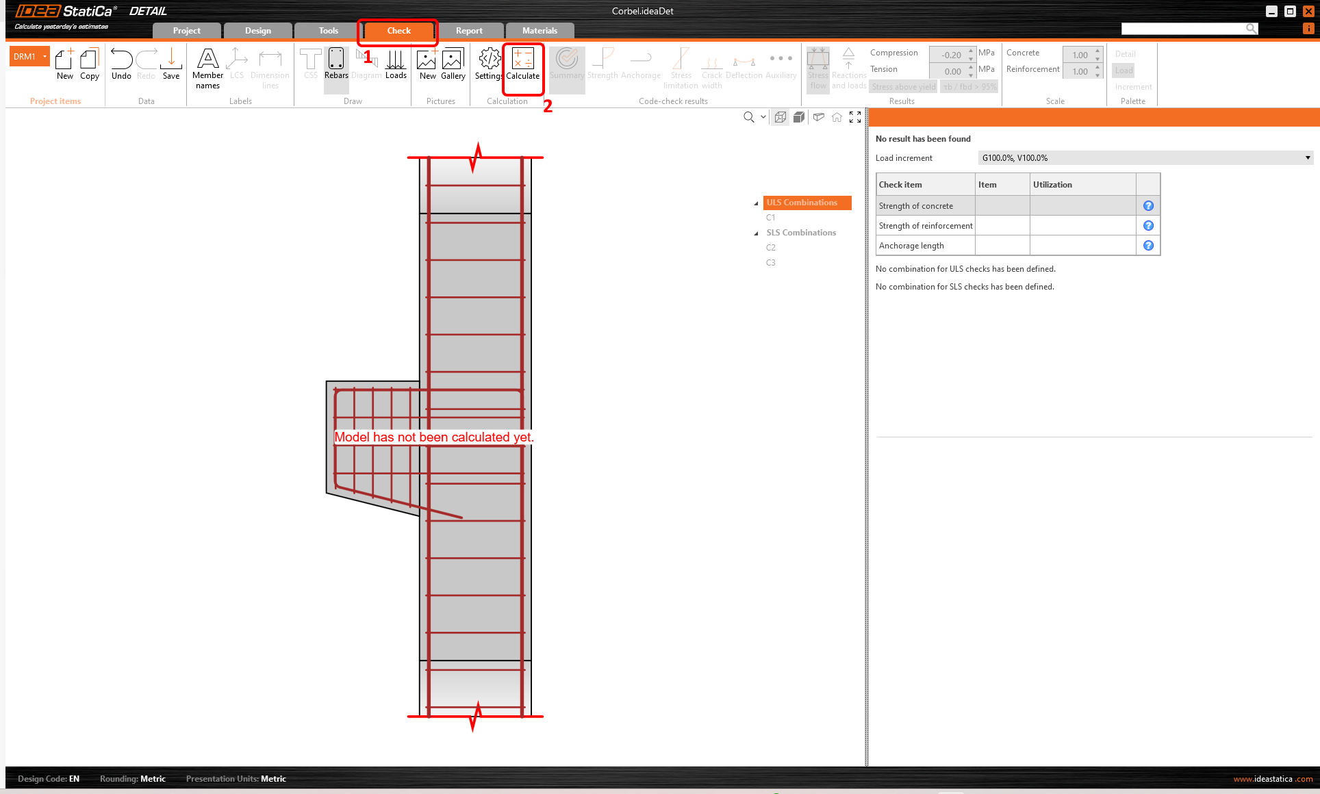
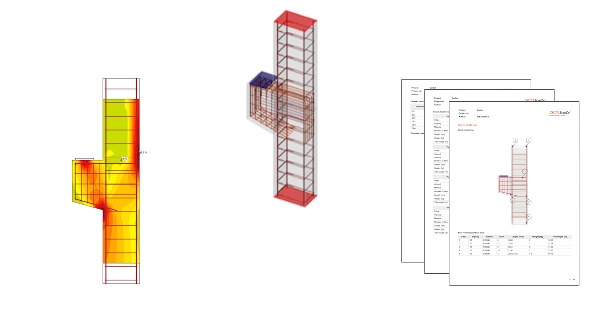
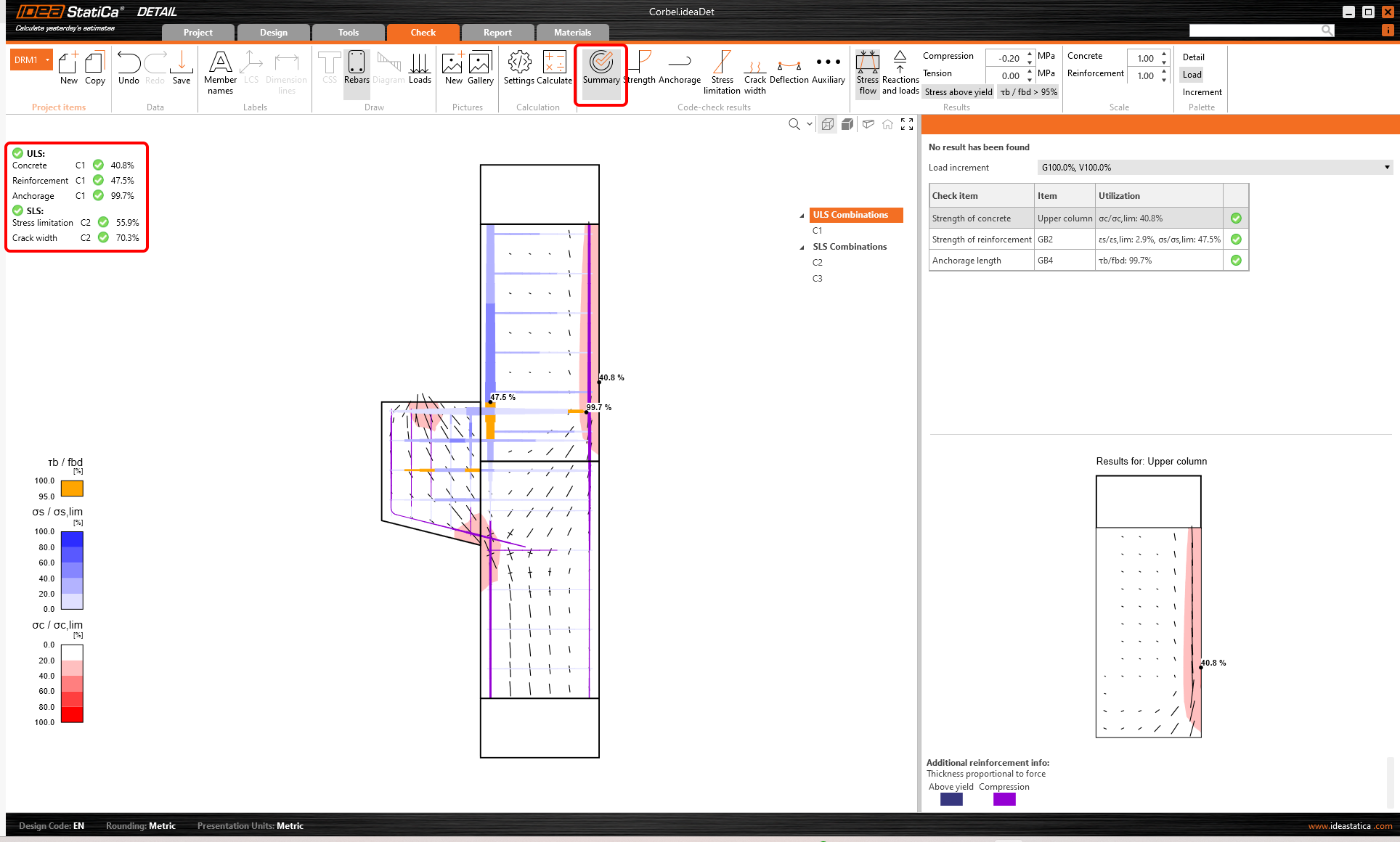
Modelul de analiză este generat automat. În stânga puteți vedea rezultatele comune, cum ar fi gradul de utilizare al materialelor. Calculele sunt efectuate și puteți vedea Rezumatul verificărilor afișat împreună cu valorile rezultatelor verificărilor.
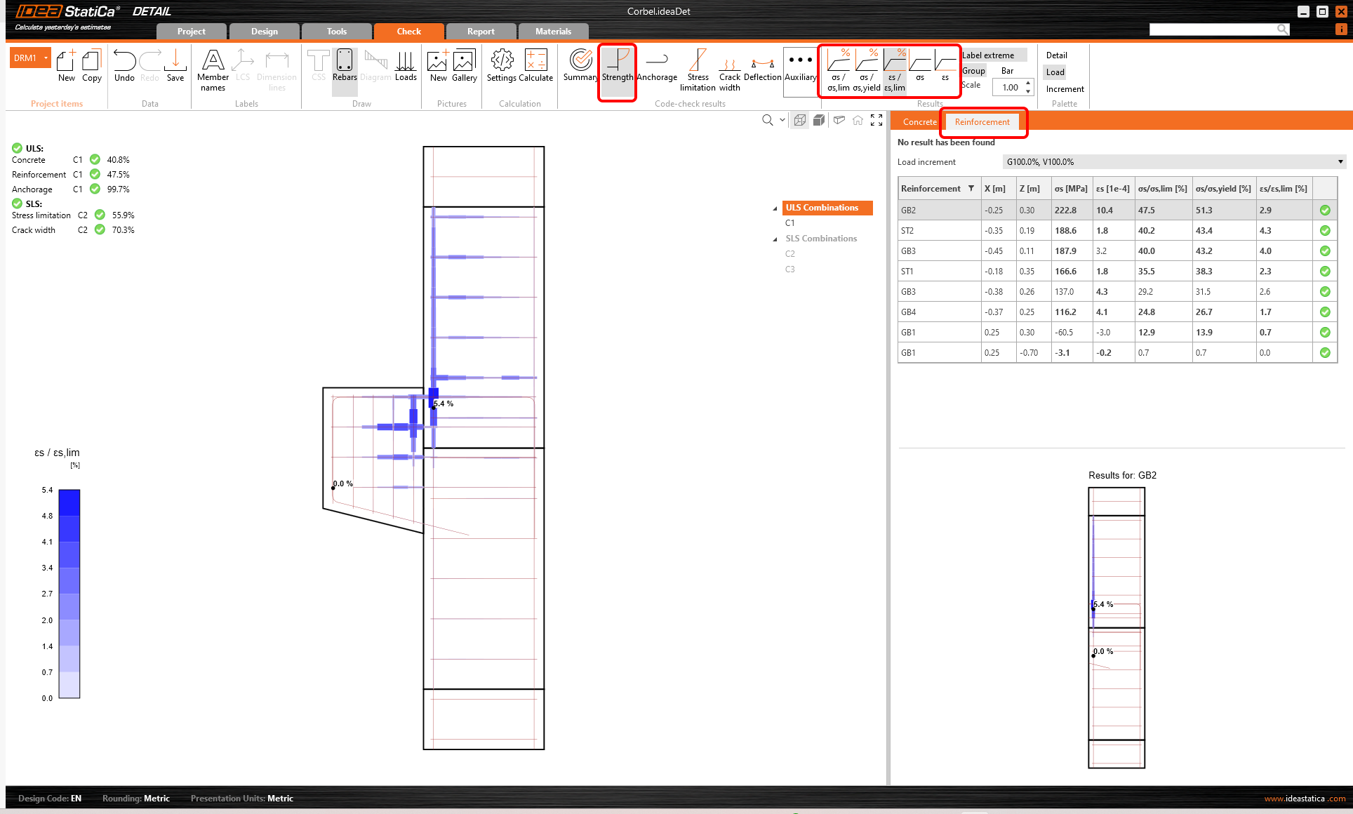
Pentru a parcurge verificările detaliate ale fiecărui component, începeți cu Rezistența. Aceasta va afișa verificările betonului, cum ar fi gradul de utilizare la tensiune, direcția tensiunilor principale, deformațiile și, de asemenea, o hartă a factorului de reducere kc, care poate fi activată din bara de instrumente. De asemenea, puteți modifica direcțiile și scara tensiunilor.
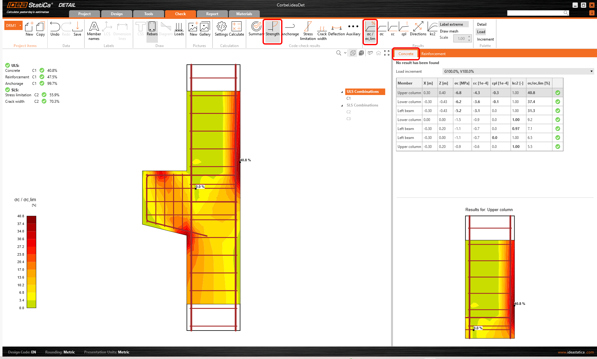
Pentru rezultatele detaliate ale armăturii, trebuie să treceți la fila Armătură. Aceasta va modifica pictogramele din bara de instrumente și va desfășura tabelul cu rezultate. Puteți afișa rezultatele pentru deformații și tensiuni în fiecare bară și gradul lor de utilizare.
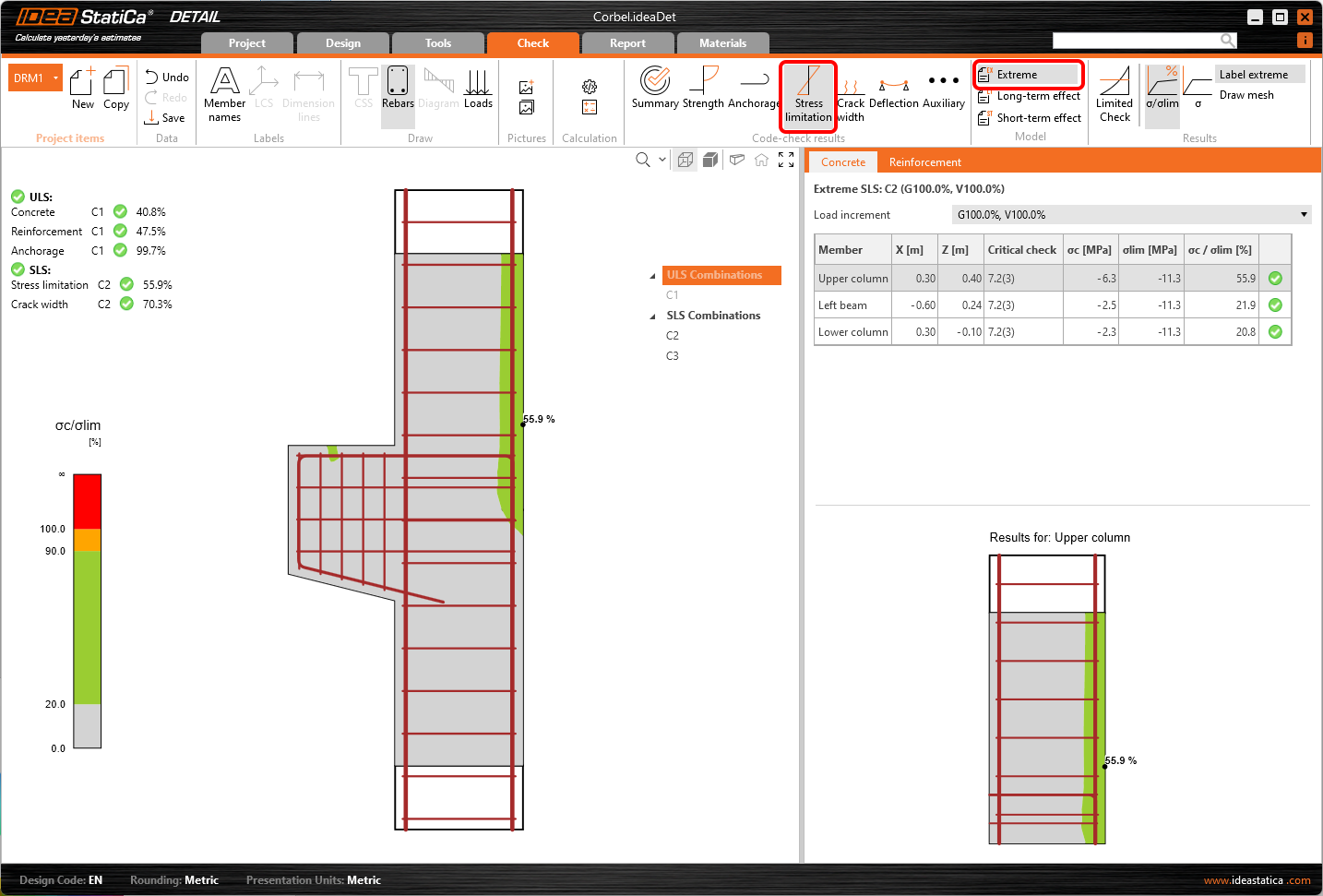
Să trecem la verificarea Limitării tensiunilor. Pe lângă pictogramele pentru comutarea între rezultate, există setări în bara de instrumente pentru specificarea valorii limită sau afișarea rezultatelor din efectele pe termen scurt/lung. Efectele pe termen scurt sunt calculate considerând modulul de elasticitate Ecm. Efectele pe termen lung iau în considerare efectul fluajului betonului, astfel că se utilizează modulul de elasticitate efectiv Ec,eff.
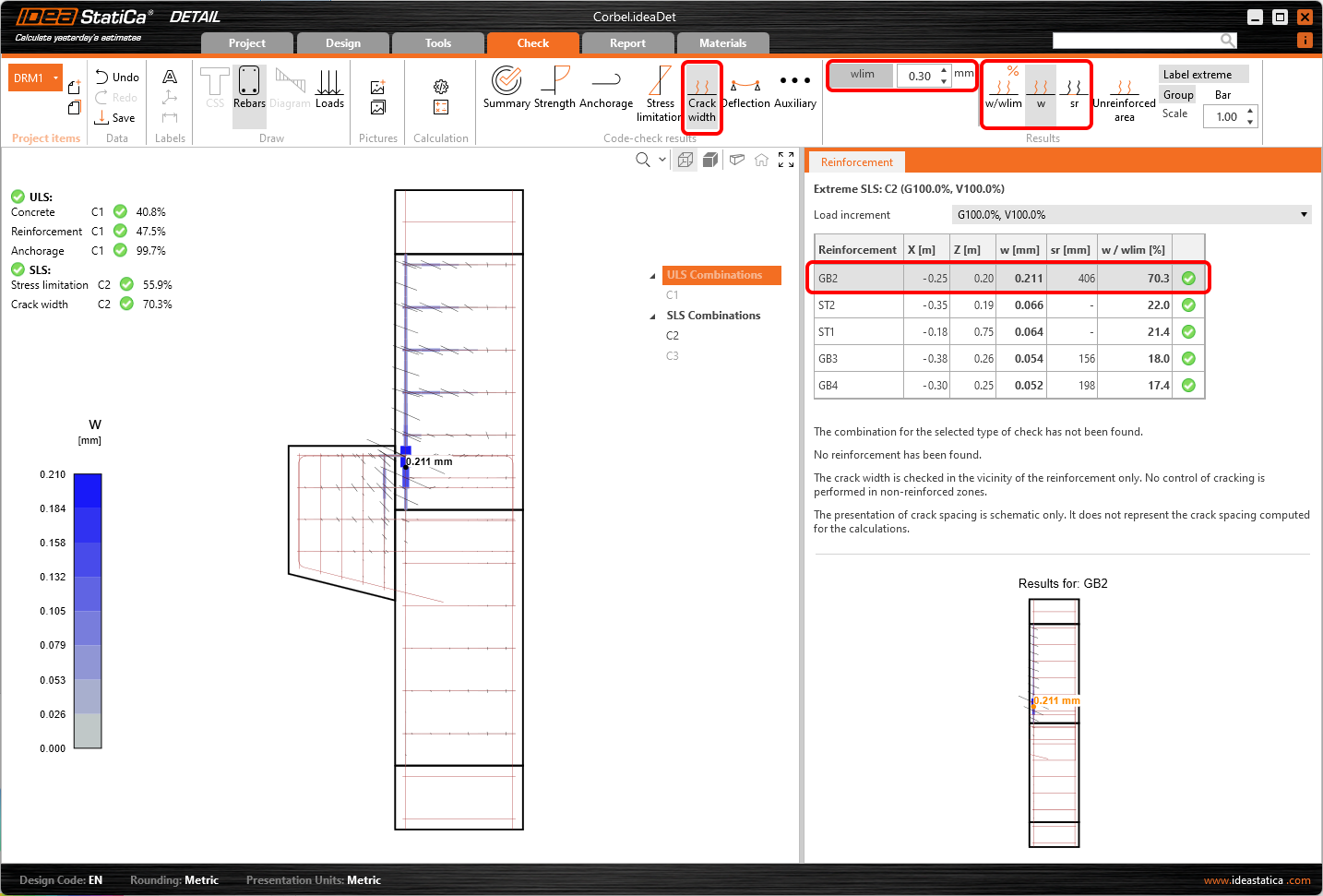
În același mod, puteți afișa și verificările SLS pentru Fisuri și alte rezultate.
6 Tipărirea raportului
Puteți Genera Lista de materiale și faceți clic pe Export în DXF pentru a genera desenele 2D. Toată armătura este exportată în blocuri care pot fi descompuse în polilinii.
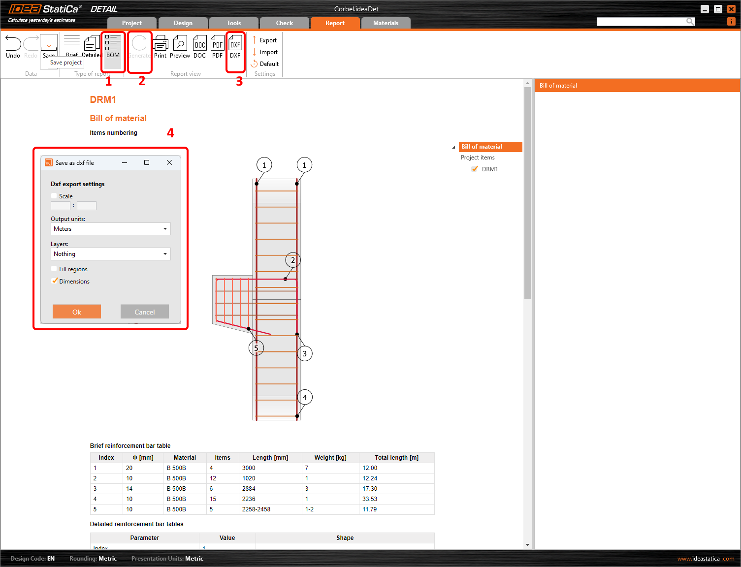
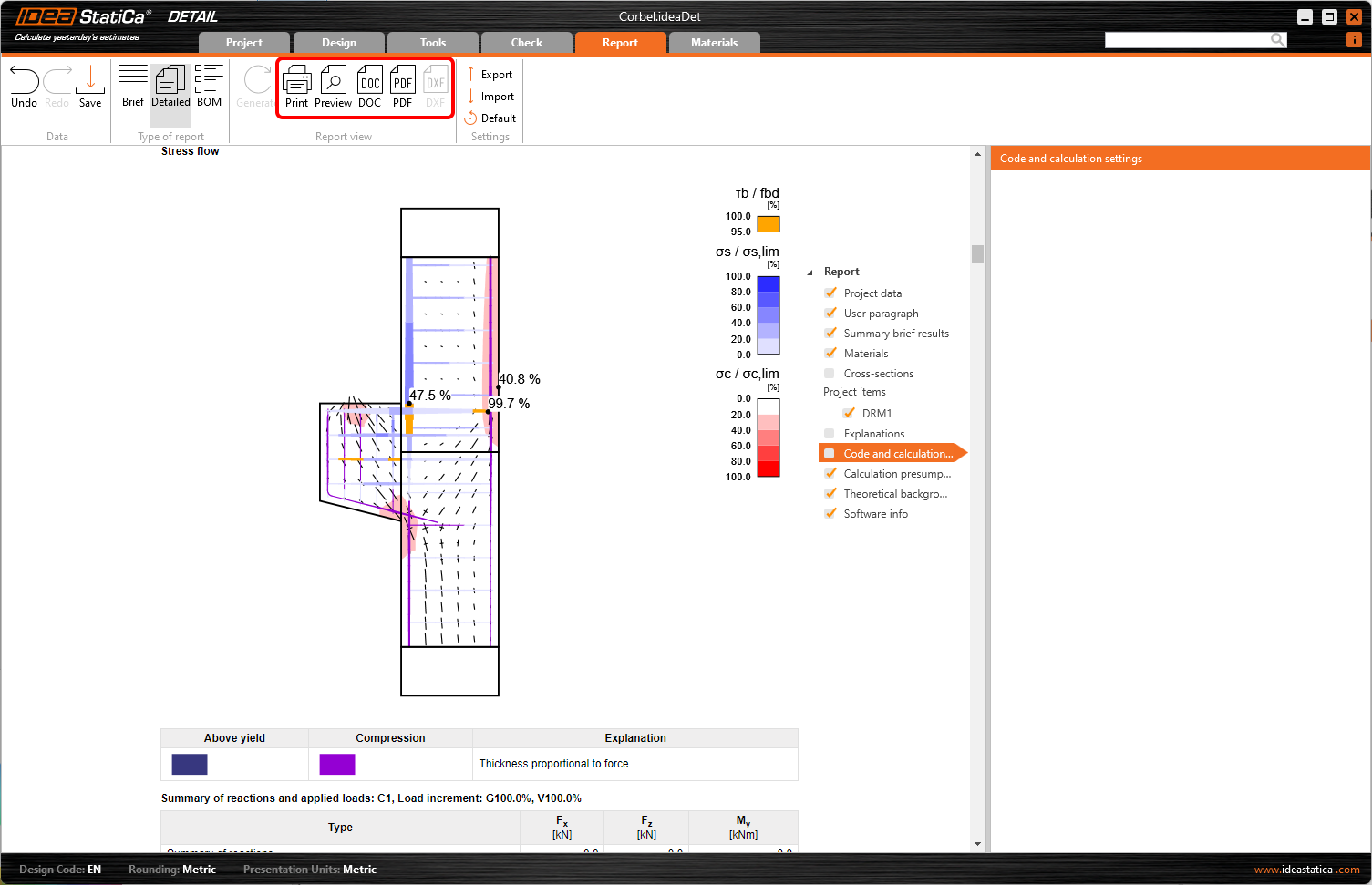
Acum este momentul să tipăriți un raport al calculelor dumneavoastră. Accesați fila Raport. Puteți alege tipul de raport Sumar sau Detaliat și puteți ajusta în continuare raportul în funcție de necesități din meniul arbore. Selectați opțiunile preferate și apăsați Generați în bara de instrumente superioară.
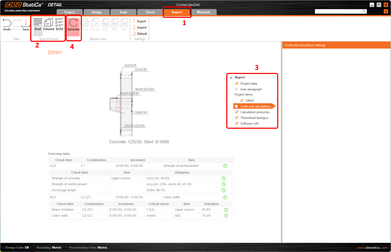
Raportul este generat și îl putem tipări în PDF sau exporta într-un fișier Microsoft Word.
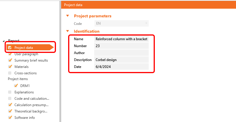
Pentru a modifica antetul raportului, accesați Datele proiectului.
Nu uitați să Salvați proiectul și am terminat!
Puteți continua să învățați IDEA StatiCa cu multe alte tutoriale în Centrul nostru de suport.