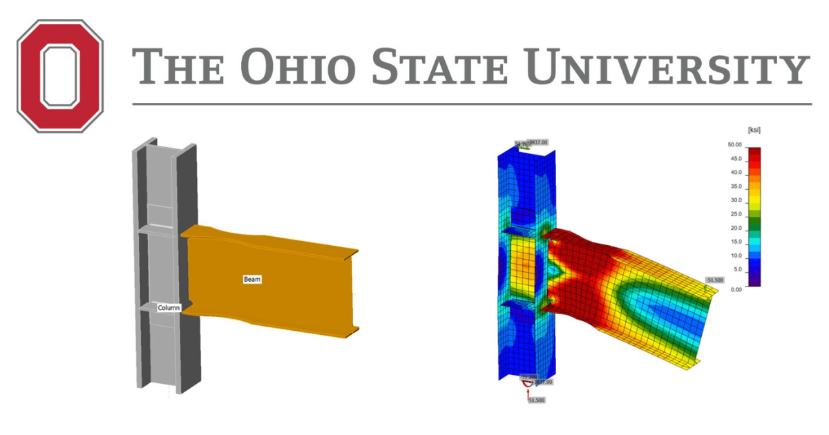
Secțiune de grindă redusă (RBS) Îmbinare preverificată - AISC
Acest exemplu de verificare a fost elaborat în cadrul unui proiect comun între Ohio State University și IDEA StatiCa. Autorii sunt enumerați mai jos:
- Baris Kasapoglu, doctorand
- Ali Nassiri, Ph.D.
- Halil Sezen, Ph.D.

1.1 Introducere
RBS este una dintre îmbinările moment preverificate permise a fi utilizate în zone seismice de AISC, ca parte a sistemelor de cadre cu moment intermediar (IMF) și cadre cu moment special (SMF), dacă sunt îndeplinite cerințele enumerate în AISC 358 Capitolul 5. Tălpile grinzii la o anumită distanță față de fața stâlpului sunt decupate cu intenția ca curgerea și articulația plastică să apară în secțiunea redusă.
În acest capitol, mai întâi, un specimen de încercare pentru îmbinarea moment cu secțiune de grindă redusă (RBS) a fost selectat din studiul experimental realizat de Uang et al. (2000) la Laboratoarele de Cercetare Structurală C. L. Powell, Universitatea California din San Diego. Acesta a fost modelat și analizat în IDEA StatiCa și ABAQUS prin reprezentarea condițiilor de încercare. Rezultatele obținute numeric au fost comparate cu observațiile din test și cu capacitatea de rezistență de calcul determinată conform cerințelor AISC 341, 358 și 360. Ulterior, au fost dezvoltate cinci variații suplimentare, iar capacitățile acestora au fost calculate folosind IDEA StatiCa și pe baza cerințelor codului AISC. La final, rezultatele au fost comparate.
1.2. Studiu experimental
Patru specimene de încercare identice au fost supuse unor istorii de încărcare diferite pentru a investiga efectele secvenței de încărcare și ale contravântuirii laterale, ca parte a proiectului SAC. Dintre acestea, primul specimen de încercare, LS-1, a fost selectat pentru a fi studiat în această cercetare, deoarece dispune de mai multe date disponibile în literatură. Detaliile îmbinării sunt prezentate în Figura 1.1.
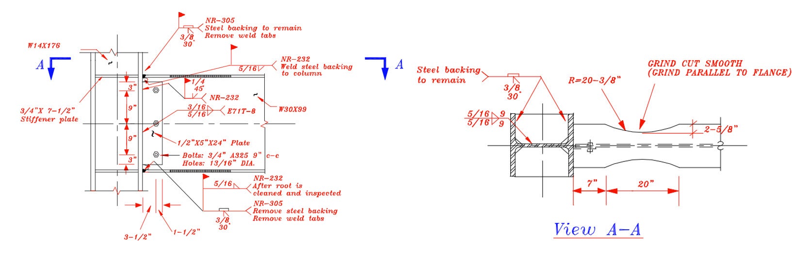
Fig. 1.1: Detaliile îmbinării (Uang et al., 2000)
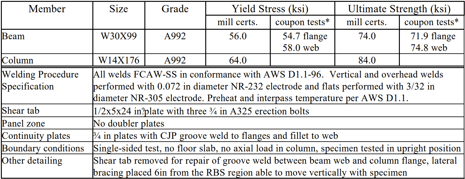
Dimensiunile grinzii și ale stâlpului sunt W30X99, respectiv W14X176, ambele fiind realizate din oțel ASTM A992. Inima și tălpile grinzii sunt sudate la talpa stâlpului prin sudură în rost cu penetrare completă (CJP), conform specificațiilor AISC 358. Detaliile procedurii de sudare și proprietățile materialelor măsurate sunt prezentate în Tabelul 1.1. Placa de continuitate cu grosimea de 3/4 in. și o teșitură de colț de 1,79 in. este realizată din ASTM A572 Grad 50. Aceasta este sudată la talpa stâlpului prin sudură în rost CJP și la inima stâlpului cu sudură dublă în colț de 5/16 in. Placa de forfecare este utilizată în scopul montajului și este îndepărtată înainte de testare.
Tabelul 1.1: Proprietățile materialelor și detaliile specimenului.
Istoricul de încărcare standard SAC cu mai mulți pași este aplicat la capătul grinzii, aflat la 149 in. față de axa stâlpului, prin intermediul unui actuator hidraulic. Stâlpul este reținut lateral, iar capătul superior și cel inferior al stâlpului sunt fixate față de peretele rigid și planșeu. Configurația de încercare și istoricul de încărcare aplicat sunt prezentate în Figura 1.2.
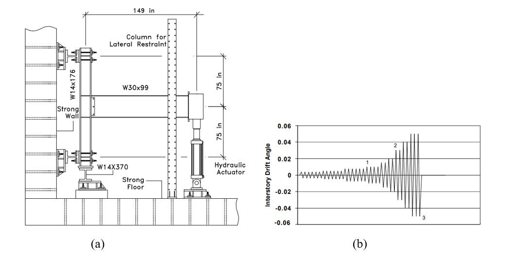
Figura 1.2: (a) Configurația de încercare; și (b) istoricul de încărcare (Uang et al., 2000).
Principalele observații făcute în timpul testului de către cercetători sunt următoarele:
- Curgere semnificativă se dezvoltă în zona RBS
- Curgere moderată a apărut în zona nodului de panou al stâlpului
- Flambajul grinzii a fost observat în timpul ciclurilor de deplasare de 3%
- Testul a fost oprit după trei cicluri la o deplasare de 5%
Relațiile forță-deplasare ale actuatorului și moment global-rotație plastică, precum și fotografiile după vârful celui de-al treilea ciclu la 5% deplasare sunt prezentate în Figurile 1.3 și 1.4
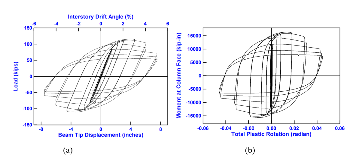
Figura 1.3: (a) Forță-deplasare actuator; și (b) relații moment global-rotație plastică (Uang et al., 2000).
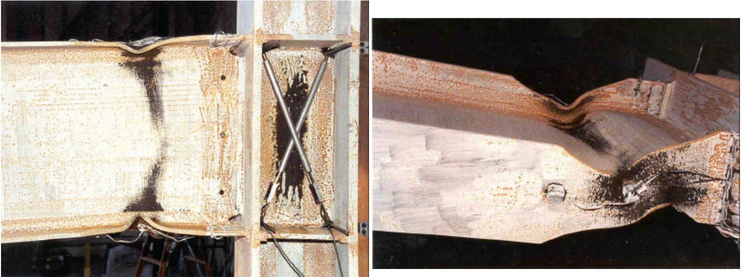
Figura 1.4: Specimen după testare (Uang et al., 2000).
1.3 Calcule de proiectare conform codului
Următoarele verificări de proiectare prezentate în AISC 358 au fost efectuate pentru specimenul de încercare selectat, și au fost dezvoltate cinci variații suplimentare.
- Verificarea limitelor de preverificare pentru stâlp și grindă (AISC 358 Secțiunea 5.3)
- Verificarea dimensiunilor RBS (AISC 358 Ec. 5.8-1-5.8-3)
- Verificarea că momentul maxim probabil la fața stâlpului, Mf, nu depășește rezistența disponibilă fdMpe. (ANSI/AISC 358 Ec. 5.8-8)
- Verificarea rezistenței la forfecare a grinzii (AISC 360-16, Ec. J4-3)
- Verificarea îmbinării inimii grinzii cu stâlpul (AISC 358 Ec. 5.8-9)
- Verificarea îmbinării inimii grinzii cu stâlpul. (AISC 358 Secțiunea 5.6)
- Verificarea cerințelor pentru plăcile de continuitate. (AISC 358 Capitolul 2)
- Verificarea relației stâlp-grindă. (AISC 358 Secțiunea 5.4)
- Verificarea rezistenței la forfecare a nodului de panou (AISC 358 Secțiunea 5.4)
- Verificarea rezistenței la încovoiere la axa centrală a RBS (AISC Specification F2-1)
Se presupune că sistemul de cadre satisface cerințele SMF. Pentru calculul forței de forfecare la centrul RBS, VRBS, distanța dintre axele stâlpilor, L, se presupune a fi egală cu 360 in. Pentru calculul de proiectare al specimenului de încercare, proprietățile materialelor bazate pe raportul de încercare al laminorului au fost utilizate pentru grindă și stâlp, în timp ce proprietățile materialelor din AISC Manual Tabelul 2-5 au fost utilizate pentru placa de continuitate. În scopul comparației, se intenționează reprezentarea condiției de încercare cu o sarcină concentrată la capătul grinzii, aflat la 149 in. față de axa stâlpului. Greutatea proprie a grinzii este neglijată. Se presupune că combinația de încărcare 6 din ASCE/SEI 7 Secțiunea 12.4.2.3 este determinantă, iar rezistența necesară la încovoiere și forfecare la fața stâlpului și la axa centrală a zonei RBS sunt după cum urmează:
- Vu@RBS = 40 kip (la axa centrală a RBS)
- Vu@FOC = 40 kip (la fața stâlpului)
- Mu@RBS = 4976 kips-in (la axa centrală a RBS)
- Mu@FOC = 5656 kips-in (la fața stâlpului)
Limitările AISC au fost verificate pentru specimenul de bază (LS-1) și prezentate în Tabelul 1.2 (pentru detalii, a se vedea Anexa A).
Tabelul 1.2: Verificări de proiectare AISC pentru specimenul de bază (LS-1)
| Verificări de proiectare AISC | LS-1 |
| Limite de preverificare pentru stâlp și grindă | OK |
| Dimensiuni RBS | OK |
| Momentul la fața stâlpului > Momentul plastic al grinzii | OK |
| Rezistența la forfecare a grinzii | OK |
| Îmbinarea inimii grinzii cu stâlpul | OK |
| Placă de continuitate (sudură dublă în colț) | Nu OK |
| Relații stâlp-grindă | OK |
| Rezistența nodului de panou | OK |
| Rezistența la încovoiere | OK |
Se observă că dimensiunea sudurii dintre placa de continuitate și inima stâlpului (sudură dublă în colț de 5/16 in.) este mai mică decât dimensiunea necesară a sudurii duble în colț de 1/2 in. conform AISC Manual Ec. 8-2a. Deși această îmbinare nu ar fi permisă a fi utilizată în sistemul SMF conform cerințelor actualizate AISC, din observațiile testului se constată că nu are un efect semnificativ asupra curgerii care apare mai întâi în zona de decupare RBS a grinzii. Rezistența la încovoiere a zonei de decupare RBS a grinzii este determinată conform AISC 360 Ec. F2-1, AISC 358 Ec. 5.8-4 și folosind \(\phi_{d}\) de 1,0 (pentru starea limită ductilă) specificat în AISC 358 Secțiunea 2.4.1, după cum urmează
Mn = Mp = Fy⋅Zx (AISC 360 Ec. F2-1)
ZRBS = Zx – 2⋅c⋅tf⋅(d-tf) (AISC 358 Ec. 5.8-4)
\(\phi_{d}\) = 1,0 (AISC 358 Secțiunea 2.4.1)
unde
- Mn : rezistența nominală la încovoiere a grinzii
- Mp : momentul plastic al grinzii
- Fy : limita de curgere minimă specificată
- Zx: modulul de rezistență plastic al grinzii raportat la axa X
- ZRBS : modulul de rezistență plastic la centrul secțiunii reduse a grinzii raportat la axa X
- d : înălțimea grinzii
- c : adâncimea decupării la secțiunea grinzii
- tf : grosimea tălpii grinzii
- \(\phi_{d}\) : Factor de rezistență pentru starea limită ductilă
Rezistența nominală și disponibilă la încovoiere la centrul zonei de decupare RBS a specimenului de bază poate fi calculată după cum urmează:
Mn@RBS = Fy⋅ZRBS = (56 ksi)⋅(209,9 in.3) = 11.754 kips-in.
\(\phi\)Mn@RBS = (1,0)⋅(11.754 kips-in.) = 11.754 kips-in.
Au fost dezvoltate cinci variații suplimentare, prezentate în Tabelul 1.3. Pentru primele trei variații, dimensiunile elementelor de stâlp și grindă au fost modificate față de modelul de bază, în timp ce ultimele două variații au fost modificate față de variația 2. Pentru a genera necesitatea unei plăci de dublare a inimii stâlpului, se presupune că există o altă grindă cu aceeași dimensiune conectată la stâlp pe cealaltă parte. Lungimea stâlpului este egală cu 400 in., în timp ce distanțele dintre axele stâlpilor se presupun a fi egale cu 400 in. și, respectiv, 300 in. Proprietățile materialelor pentru stâlp și grindă (ASTM A992) și placa de continuitate (ASTM A572 Grad 50) din AISC Manual Tabelele 2-4 și 2-5 sunt după cum urmează:
ASTM A992
Fy = 50 ksi
Fu = 65 ksi
ASTM A572 Grad 50
Fy = 50 ksi
Fu = 65 ksi
Verificările de proiectare au fost efectuate urmând aceeași procedură prezentată în Tabelul 1.4. Capacitățile de proiectare calculate sunt prezentate în Tabelul 1.5 (pentru detalii privind Var-4, a se vedea Anexa B).
Tabelul 1.3: Proprietățile variațiilor
| Proprietăți | LS-1 | LS-2 | LS-3 | LS-4 | LS-5 | LS-6 |
| Stâlp | W14X176 | W14X176 | W14X176 | W18X192 | W12X170 | W12X136 |
| Grosimea plăcii de dublare | - | - | - | - | 3/8 in. | 1/2 in. |
| Grindă | W30X99 | W27X94 | W24X68 | W30X99 | W24X68 | W24X68 |
| Decupare grindă - a [in.] | 7 | 6 | 5 | 7 | 5 | 5 |
| Decupare grindă - b [in.] | 20 | 19 | 17 | 20 | 17 | 17 |
| Decupare grindă - c [in.] | 2,63 | 2 | 2 | 2,63 | 2 | 2 |
| Placă de rigidizare - grosime [in.] | 0,75 | 0,75 | 0,75 | 0,75 | 0,75 | 0,75 |
| Placă de rigidizare - înălțime [in.] | 7,5 | 7,5 | 7,5 | 7,5 | 7,5 | 7,5 |
| Placă de rigidizare - lungime [in.] | 9 | 9 | 9 | 9 | 9 | 9 |
| Placă de rigidizare - sudură dublă [in.] | 0,31 | 0,31 | 0,31 | 0,31 | 0,31 | 0,31 |
Tabelul 1.4: Verificări de proiectare pentru variații
| Verificări de proiectare AISC | Var-1 | Var-2 | Var-3 | Var-4 | Var-5 | Var-6 |
| Limite de preverificare pentru stâlp și grindă | OK | OK | OK | OK | OK | OK |
| Dimensiuni RBS | OK | OK | OK | OK | OK | OK |
| Momentul la fața stâlpului > Momentul plastic al grinzii | OK | OK | OK | OK | OK | OK |
| Rezistența la forfecare a grinzii | OK | OK | OK | OK | OK | OK |
| Îmbinarea inimii grinzii cu stâlpul | OK | OK | OK | OK | OK | OK |
| Placă de continuitate (sudură dublă în colț) | Nu OK | Nu OK | Nu OK | Nu OK | Nu OK | Nu OK |
| Relații stâlp-grindă | OK | OK | OK | OK | OK | OK |
| Rezistența nodului de panou | OK | OK | OK | OK | OK | OK |
| Rezistența la încovoiere | OK | OK | OK | OK | OK | OK |
Tabelul 1.5: Capacitățile de proiectare ale variațiilor
| Variații | Dimensiune stâlp | Dimensiune grindă | Grosimea plăcii de dublare | Rezistența de proiectare disponibilă la încovoiere la axa centrală a zonei de decupare RBS a grinzii (kips-in.) |
| Var-1 | W14X176 | W27X94 | - | 9.978 |
| Var-2 | W14X176 | W24X76 | - | 6.146 |
| Var-3 | W18X192 | W30X99 | - | 11.750 |
| Var-4 | W12X170 | W24X76 | 3/8 in. | 6.146 |
| Var-5 | W12X136 | W30X99 | 1/2 in. | 6.146 |
1.4. Analiza IDEA StatiCa
Au fost efectuate două analize diferite în IDEA StatiCa. Prima are scopul de a investiga capacitatea specimenului de bază în condiții de încercare, în timp ce a doua urmărește calculul relației moment-rotație a îmbinării. Mai întâi, specimenul de încercare a fost modelat în IDEA StatiCa. Apoi, proprietățile materialelor din certificatul de laminare au fost introduse, iar coeficienții de suprarezistență, Ry și Rt, au fost setați egali cu 1,0 (a se vedea Figura 1.5). De asemenea, toți factorii de rezistență LRFD au fost setați la 1,0, după cum se arată în Figura 1.6.
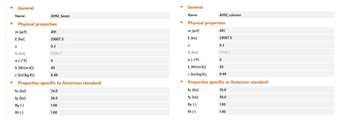
Figura 1.5: Proprietățile materialelor specimenului de încercare în IDEA StatiCa; a) grindă, b) stâlp.
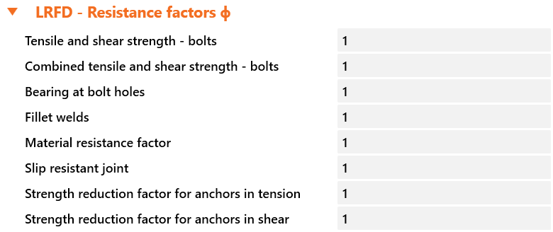
Figura 1.6: Factorii de rezistență LRFD în IDEA StatiCa.
1.4.1 Analiza capacității
Pentru calculul capacității, a fost ales tipul de analiză „EPS". Apoi, opțiunea „Loads in equilibrium" a fost selectată pentru a reprezenta condițiile de configurare a testului sub „Design". În această selecție, forțele interioare la fiecare nod al cadrului trebuie introduse în sistem. Lungimea implicită a stâlpului în modelul IDEA StatiCa este egală cu 194,55 in. (2·(4+1,25)·bc+db). Deoarece versiunea curentă a IDEA StatiCa nu permite modificarea lungimii stâlpului, se presupune că lungimea stâlpului din modelul IDEA este egală cu lungimea configurației de încercare (150 in.). Se presupune că stâlpul este încastrat la ambele capete, după cum se prezintă în Figura 1.7(a), iar încărcările care urmează a fi aplicate modelului folosind opțiunea „loads in equilibrium" (Figura 1.7(b)) pot fi calculate după cum urmează:
V = P·(149 in.)/150 in.
M = P·(149 in.)/2
N = P
unde
- P: sarcina verticală aplicată pe grindă la poziția de 149 in.
- V: forța tăietoare aplicată la capetele stâlpului
- N: forța axială aplicată la baza stâlpului
- M: momentul aplicat la capetele stâlpului
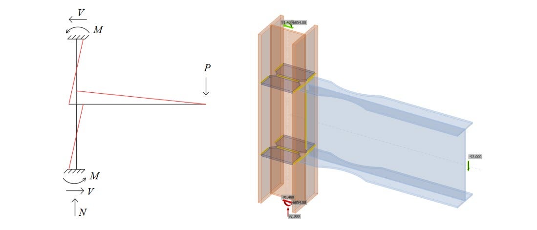
Figura 1.7: (a) Încărcări în sistemul de cadre și (b) Încărcări în IDEA StatiCa când P = 92 kips.
După aplicarea încărcării incrementale în IDEA StatiCa prin actualizarea tuturor încărcărilor la fiecare pas, s-a observat că curgerea începe în zona RBS a tălpii inferioare când sarcina verticală, P, aplicată pe grindă la 149 in. față de axa stâlpului a atins 92 kips. Distanța dintre punctul de aplicare a sarcinii și centrul zonei de decupare RBS, LRBS, poate fi calculată prin scăderea din 149 in. a jumătății din înălțimea stâlpului și a distanței dintre centrul zonei de decupare RBS și fața stâlpului, astfel:
LRBS = 149 in. – (15,2 in./2) – 17 in. = 124,4 in.
Valoarea momentului la centrul zonei de decupare RBS, MyRBS-IDEA, produsă de sarcina verticală aplicată, P, poate fi calculată astfel:
MyRBS-IDEA = P⋅LRBS = MyRBS-IDEA = (124,4 in.)⋅(92 kips) = 11.445 kips-in. (Figura 1.8)
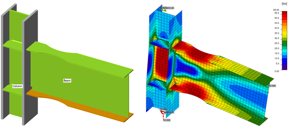
Figura 1.8: Modelul IDEA StatiCa pentru LS-1.
Modelele IDEA StatiCa pentru cele cinci variații suplimentare de îmbinări (a se vedea Tabelul 1.3) au fost dezvoltate folosind proprietățile materialelor specificate de AISC din AISC Manual Tabelele 2-4 și 2-5, prezentate în Figura 1.9.
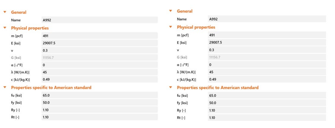
Figura 1.9: Proprietățile materialelor pentru variații în IDEA StatiCa; a) grindă, b) stâlp.
Urmând aceeași procedură, capacitățile celor cinci variații de îmbinări au fost calculate folosind IDEA StatiCa, prezentate în Tabelul 1.6 și Figurile 1.10-1.14.
Tabelul 1.6: Capacitățile de proiectare ale variațiilor
| Variații | Dimensiune stâlp | Dimensiune grindă | Grosimea plăcii de dublare | Rezistența de proiectare disponibilă la încovoiere la axa centrală a zonei de decupare RBS a grinzii (kips-in.) |
| Var-1 | W14X176 | W27X94 | - | 9.644 |
| Var-2 | W14X176 | W24X68 | - | 6.587 |
| Var-3 | W18X192 | W30X99 | - | 10.490 |
| Var-4 | W12X170 | W24X68 | 3/8 in. | 6.587 |
| Var-5 | W12X136 | W24X68 | 1/2 in. | 6.587 |
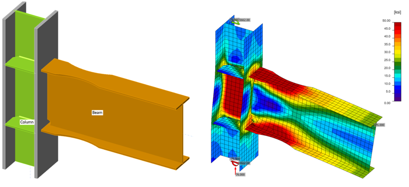
Figura 1.10: Modelul IDEA StatiCa pentru variația 1.
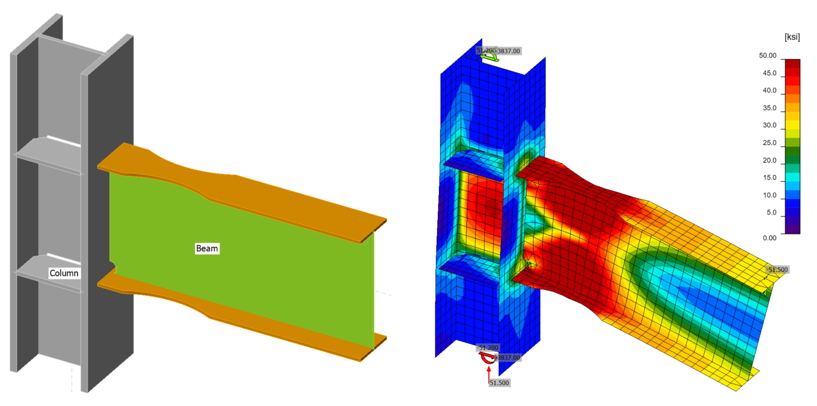
Figura 1.11: Modelul IDEA StatiCa pentru variația 2.
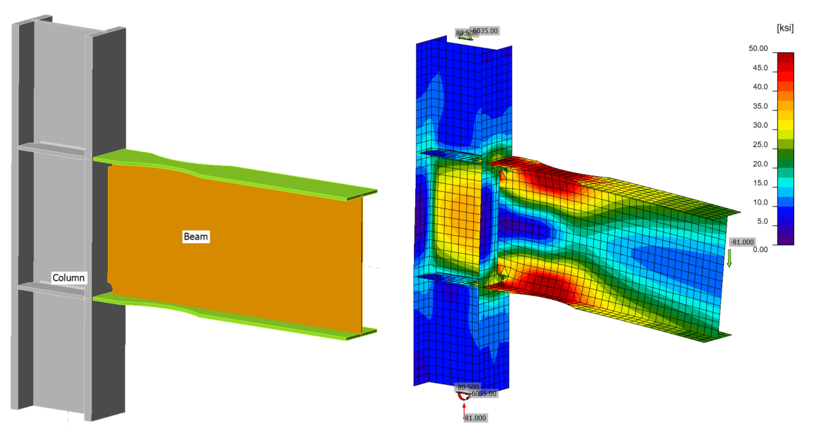
Figura 1.12: Modelul IDEA StatiCa pentru variația 3.
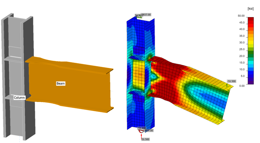
Figura 1.13: Modelul IDEA StatiCa pentru variația 4.
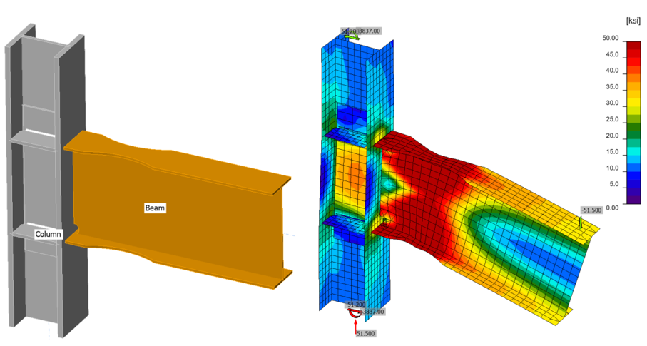
Figura 1.14: Modelul IDEA StatiCa pentru variația 5.
1.4.2 Analiza moment-rotație
Analiza moment-rotație este calculată cu tipul de analiză „ST" (abreviere pentru rigiditate). Forța verticală maximă aplicată în timpul experimentului, 115 kips, a fost aplicată la poziția grinzii de 0 (zero) in. în direcția negativă z (Vz = -115 kips), iar momentul corespunzător de 17.135 kips-in. (115 kips×149 in.) este aplicat în jurul axei Y (My = 17.135 kips-in.), după cum se prezintă în Figura 1.15.
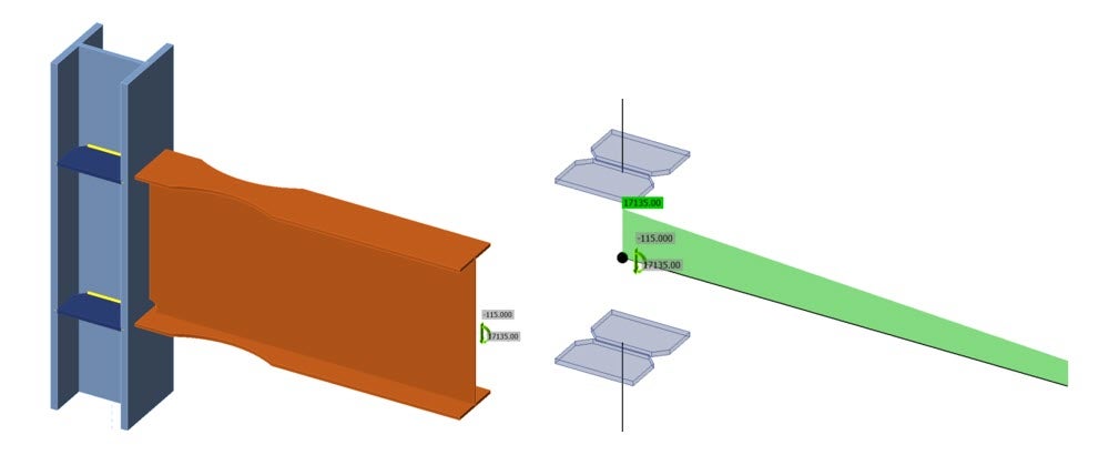
Figura 1.15: Analiza ST în IDEA StatiCa: (a) vedere solidă; (b) vedere tip cadru.
Sub aceste încărcări, graficul moment-rotație excluzând rotația elastică a grinzii și stâlpului a fost obținut după cum se arată în Figura 1.16, unde:
- Sj: curba moment-rotație reprezentată cu
- Sj,R: valoare limită – îmbinare rigidă
- Sj,P: valoare limită – îmbinare articulată nominal
- Sj,ini: rigiditatea de rotație inițială
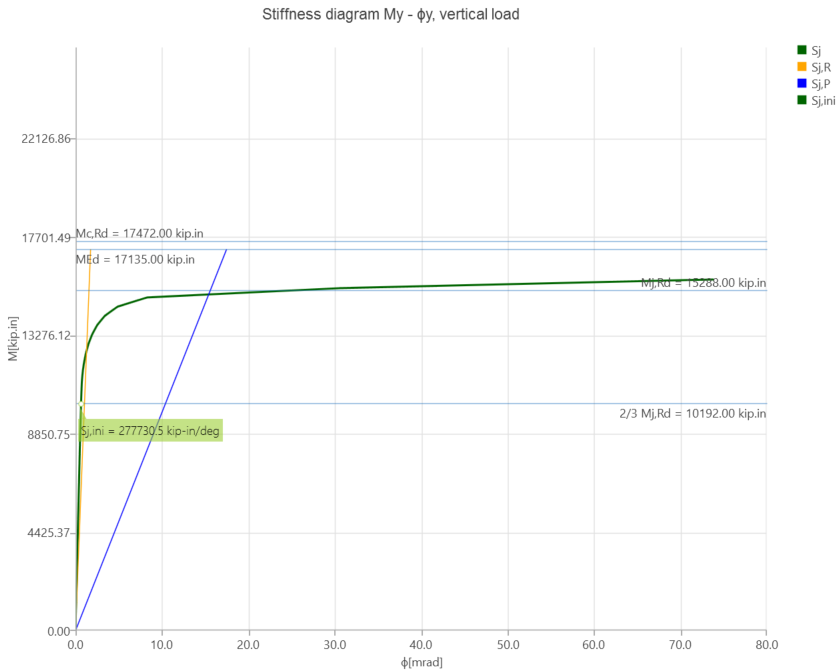
Figura 1.16: Relația moment-rotație calculată de IDEA StatiCa.
1.5. Analiza ABAQUS
În această secțiune, rezultatele din IDEA StatiCa au fost comparate cu pachetul software ABAQUS (versiunea 2021). ABAQUS este un cod FEA robust de uz general, adecvat pentru analiza unei game largi de probleme statice, dinamice și neliniare.
În acest studiu, modelul IDEA StatiCa dezvoltat în Secțiunea 1.4.2 pentru analiza moment-rotație a fost ales ca model de bază. Modelul CAD pentru analiza FEA a fost generat folosind platforma de vizualizare a IDEA StatiCa. Simulările numerice cu condiții aproape identice (adică în ceea ce privește proprietățile materialelor, condițiile la limită și încărcarea) au fost efectuate atât în IDEA StatiCa, cât și în ABAQUS.
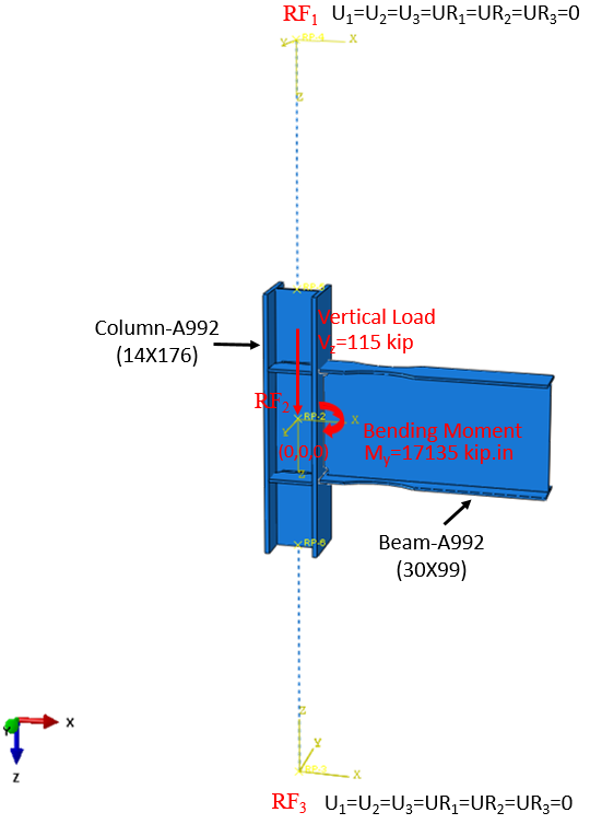
Figura 1.17: Configurarea modelului în ABAQUS.
În ABAQUS, dimensiunea și tipul elementului au fost alese ca 5 mm și C3D8R (tensiune 3D, element hexaedric liniar cu 8 noduri, integrare redusă), respectiv. În modelul ABAQUS, sarcina verticală de 115 kips și momentul corespunzător de 17.135 kips-in. (în jurul axei Y) au fost aplicate unui punct de referință definit (adică RF2), după cum se arată în Figura 1.17. Lungimea calculată a stâlpului în IDEA StatiCa este de 194,55 in., după cum s-a descris în Secțiunea 1.4.1. Prin urmare, pentru a reproduce lungimea identică a stâlpului în ABAQUS, două puncte de referință (adică RF1 și RF3) au fost introduse la 97,245 in. față de centrul stâlpului de-a lungul axei Z în ambele direcții. Aceste două puncte de referință au fost fixate în toate direcțiile și au fost conectate la fețele superioară și inferioară ale stâlpului folosind un modul de tip conector în ABAQUS. Constrângerea de tip tie a fost aplicată între liniile de sudură și piesele atașate. Comportamentul materialului a fost modelat folosind plasticitate bi-liniară în ABAQUS. Alți parametri, inclusiv densitatea, modulul de elasticitate și coeficientul Poisson, au fost preluați din biblioteca de materiale a IDEA StatiCa. Simularea numerică a fost efectuată pe patru procesoare (Intel Xenon (R) CPU E5-2698 v4 @ 2,20GHz) și a durat aproximativ 45 de minute. Figura 1.18 compară tensiunea von Mises și deformația plastică prezise între modelele IDEA StatiCa și ABAQUS.
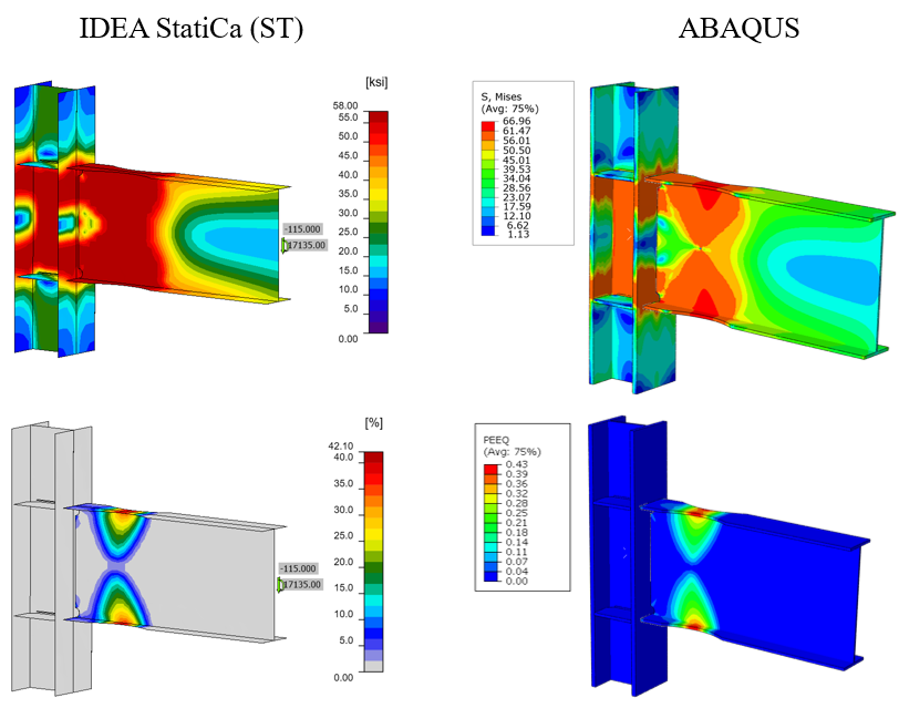
Figura 1.18: Comparație a tensiunii von Mises prezise (rândul de sus) și a deformației plastice (rândul de jos) între modelele IDEA StatiCa și ABAQUS.
Tensiunea maximă prezisă în IDEA StatiCa este de 68 ksi (pe fața superioară și inferioară a secțiunii reduse a grinzii), în timp ce modelul ABAQUS arată tensiunea maximă de 66,96 ksi la aceeași locație. Distribuția ușor diferită a tensiunilor se datorează probabil utilizării unei plase mai fine în modelul ABAQUS și a modelului CAD simplificat în IDEA StatiCa. De asemenea, deformația plastică maximă prezisă în IDEA StatiCa și ABAQUS este de 41,3%, respectiv 43%.
Figura 1.19 prezintă comparația curbei moment-rotație între cele două programe.
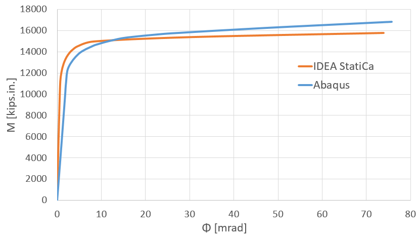
Figura 1.19: Comparație moment-rotație între IDEA StatiCa și ABAQUS.
De remarcat că în Figura 19, curba albastră (adică rezultatul din ABAQUS) reprezintă rotația grinzii, măsurată la intersecția stâlpului cu grinda. Ambele modele oferă estimări comparabile ale rigidității inițiale. Discrepanța minoră ar putea fi asociată cu modul în care rotația este măsurată în fiecare program, diferența dintre tipurile de elemente (adică element solid în ABAQUS față de element de tip placă în IDEA StatiCa) și utilizarea constrângerii de tip tie în ABAQUS pentru reprezentarea sudurilor.
1.6 Rezumat și comparație a rezultatelor
Sarcina la capăt care produce curgerea la zona de decupare RBS, calculată folosind IDEA StatiCa, este de 92 kips. Capacitatea de proiectare la încovoiere a specimenului de încercare, calculată conform cerințelor codului AISC, a fost împărțită la distanța de la centrul zonei de decupare RBS la actuator, iar sarcina corespunzătoare la capăt a fost calculată ca 94,5 kips (11.754 kips-in./124,4 in.). Aceste două valori sunt prezentate în graficul istoricului forță-deplasare din raportul de încercare, iar cele trei surse (observație din test, calcul AISC și IDEA StatiCa) au fost comparate în Figura 1.20. Capacitatea îmbinării determinată de IDEA StatiCa este cu aproximativ 3% mai mică decât cea calculată pe baza procedurii AISC. Deși este dificil de precizat când a început curgerea din istoricul forță-deplasare, se pare că ambele abordări surprind foarte bine punctul de curgere.
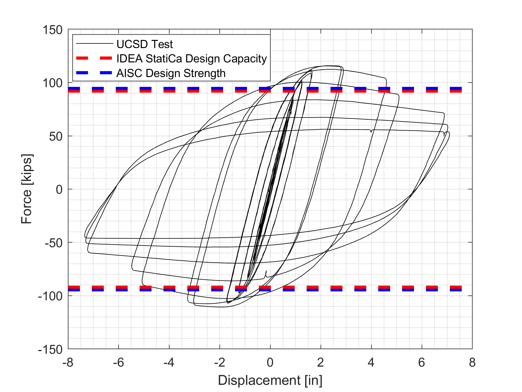
Figura 1.20: Relația forță-deplasare.
Relația moment-rotație furnizată de IDEA StatiCa include doar rotațiile plastice. Pentru a putea calcula rotația plastică, cercetătorii care au efectuat testul au calculat analitic rotațiile elastice pentru nodul de panou, grindă și stâlp și le-au inclus în fișierul de ieșire al testului. Folosind aceste date, relația moment-rotație elastică a fost obținută și adăugată la curba moment-rotație plastică a IDEA StatiCa pentru a fi comparată cu relația moment-rotație măsurată, după cum se arată în Figura 1.21.
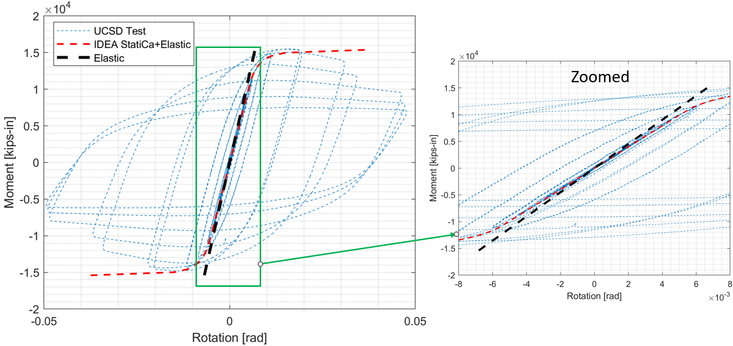
Figura 1.21: Comparație moment-rotație.
IDEA StatiCa prezintă o estimare foarte bună a rigidității inițiale și a curgerii. Diferența după curgere poate fi atribuită modelului de material biliniar utilizat de IDEA StatiCa. Aceasta a condus la faptul că ecruisajul materialului de oțel măsurat în timpul testului nu este surprins de IDEA StatiCa.
Capacitatea la încovoiere a specimenului de încercare și a celor cinci variații, calculată folosind IDEA StatiCa și conform cerințelor codului AISC, este prezentată în Tabelul 1.7. Diferențele dintre capacitățile calculate sunt mai mici de 4%.
Tabelul 1.7: Capacitatea la încovoiere a specimenului de încercare și a celor cinci variații
| Nr. specimen | Dimensiune stâlp | Dimensiune grindă | Capacitatea disponibilă la încovoiere a grinzii calculată conform procedurii AISC (kip-in.) | Capacitatea disponibilă la încovoiere a grinzii calculată folosind IDEA StatiCa (kip-in.) |
| LS-1 | W14X176 | W30X99 | 11.754 | 11.445 |
| Var-1 | W14X176 | W27X94 | 9.644 | 9.454 |
| Var-2 | W14X176 | W24X68 | 6.587 | 6.407 |
| Var-3 | W18X192 | W30X99 | 10.490 | 10.076 |
| Var-4 | W12X170 | W24X68 | 6.587 | 6.407 |
| Var-5 | W12X136 | W24X68 | 6.587 | 6 |
În concluzie, pe baza analizelor efectuate în acest capitol, s-a constatat o bună concordanță în surprinderea capacității de curgere a îmbinării RBS folosind IDEA StatiCa.
Citiți studiul complet privind îmbinările preverificate!
Referințe
Uang, C., Yu, K., and Gilton, C. (2000) Cyclic Response of RBS Moment Connections: Loading Sequence and Lateral Bracing Effects, Report No. SSR-99/13, C. L. Powell Structural Research Laboratories, University of California at San Diego.
AISC (2016), "Specification for Structural Steel Buildings," American Institute of Steel Construction ANSI/AISC 360-16, Chicago, Illinois.
AISC (2016), "Prequalified Connections for Special and Intermediate Steel Moment Frames for Seismic Applications, including Supplement No. 1," American Institute of Steel Construction ANSI/AISC 358-16, Chicago, Illinois.
AISC (2016), "Seismic Provisions for Structural Steel Buildings," American Institute of Steel Construction ANSI/AISC 341-16, Chicago, Illinois.
AISC (2020), "Seismic Design Manual," 3rd edition, American Institute of Steel Construction, Chicago.
AISC (2017), "Steel Construction Manual," 15th edition, American Institute of Steel Construction, Chicago, Illinois.
ABAQUS 2021, Dassault Systemes Simulia Corporation, Providence, RI, USA.
IDEA StatiCa s.r.o., Sumavska 519/35, Brno, 602 00 Czech Republic; https://www.ideastatica.com/support-center/general-theoretical-background