BGT-resultaten in RCS - Spanningsbegrenzing, Scheurwijdte, Detaillering
Er zijn vier tabbladen gericht op BGT-resultaten in de applicatie.
- Algemene resultaten
- Spanningsbegrenzing
- Scheurwijdte
- Detaillering
In het eerste tabblad vindt u een beknopt overzicht van de algemene resultaten. U ziet alleen de resultaten van de analyse die u hebt geselecteerd via de berekeningsbesturing.
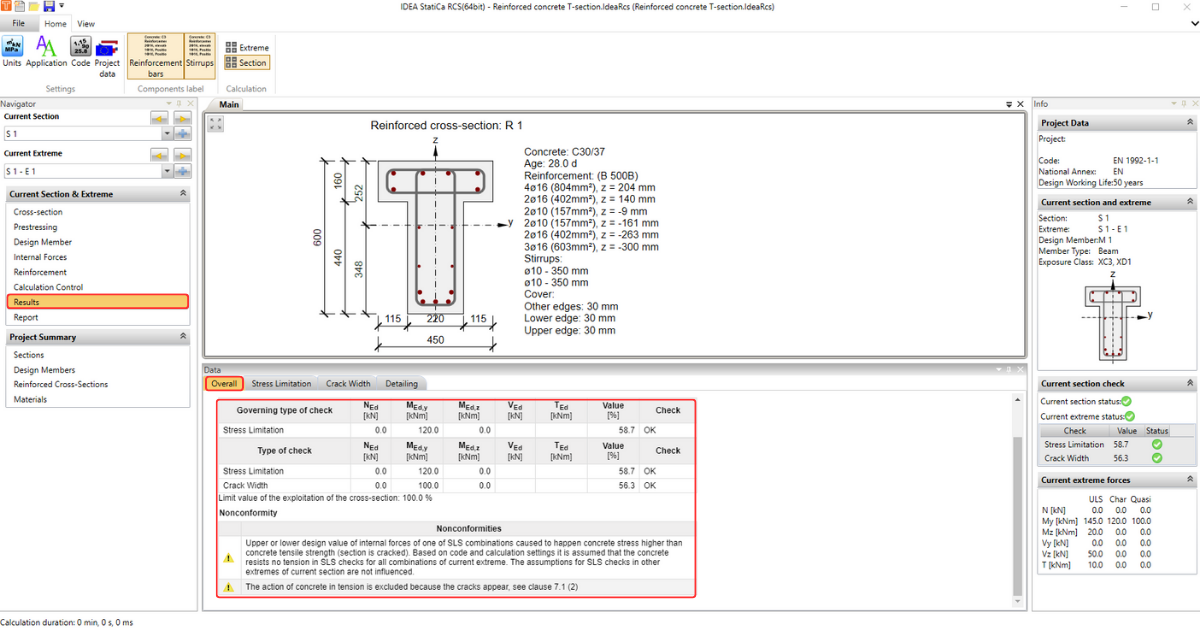
De overige tabbladen zijn gewijd aan afzonderlijke normtoetsingen. Maar voordat we deze bekijken, moeten we de aannames van de berekening begrijpen. Lees daarom het artikel: Berekeningsaannames voor BGT. Met deze kennis kunnen we vervolgens de afzonderlijke resultaten stap voor stap doorlopen.
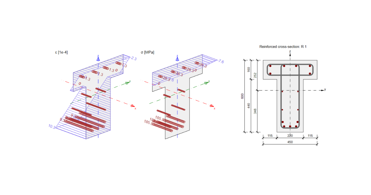
Spanningsbegrenzing
Als eerste is er de normtoetsing voor spanningsbegrenzing. Deze berekening geeft een vergelijking van de berekende spanning met grenswaarden volgens de Eurocode. Hoe specifieke waarden worden verkregen en welke basisgevallen (in termen van spanningsgrens) worden opgelost, kunt u vinden in het artikel: Normtoetsing spanningsbegrenzing.
We onderzoeken hoe u met de resultaten kunt werken en hoe u deze eventueel kunt beïnvloeden, zodra we een idee hebben van de indeling en weergaveopties.
Indeling
Controleer het bovenste lint; het gedeelte Instellingen is gewijd aan Code- en projectgegevens. Dit is hetzelfde voor alle stappen van de workflow.
De volgende onderdelen zijn al anders. Let op de onderstaande afbeelding; er zijn opties gemarkeerd voor het aanpassen van de grafische weergave van het resultaat:
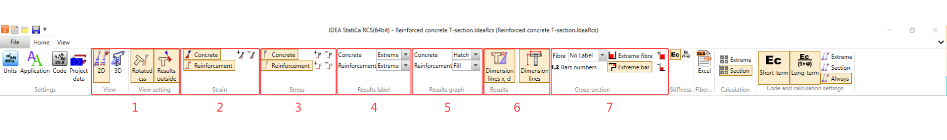
Beschrijving van opties:
- Optie om te schakelen tussen 2D- en 3D-weergave. Voor de 2D-weergave kan worden gekozen of een geroteerde doorsnede of het resultaat aan de binnen-/buitenzijde van de doorsnede wordt weergegeven.
- Het tabblad wordt gebruikt om het rekdiagram voor de beton- en wapeningsdoorsnede in/uit te schakelen en de grootte ervan aan te passen.
- Het tabblad wordt gebruikt om het spanningsdiagram voor de beton- en wapeningsdoorsnede in/uit te schakelen en de grootte ervan aan te passen.
- De optie om extreme waarden van de diagrammen weer te geven: alle of geen.
- Vervolgens kan de vulling van het diagram worden aangepast.
- Met de volgende twee knoppen kunnen maatlijnen in/uit worden geschakeld.
- Het laatste gedeelte is gewijd aan de doorsnede. Er is de optie om staaf- en vezelnummers weer te geven en hun positie aan te passen. Ook kunnen de extreme staaf en vezel worden weergegeven.
Berekening
De overige knoppen in het bovenste lint zijn gerelateerd aan de berekening zelf.
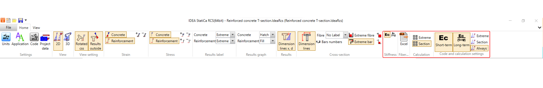
Voor de spanningsbegrenzing zijn er 4 normtoetsingen, zoals vermeld aan het begin van het hoofdstuk. De eerste twee toetsingen, volgens 7.2 (2) en 7.2 (3), worden uitgevoerd voor beide gevallen: met of zonder invloed van de langetermijneffecten (reologie van beton).
Voor de kortetermijneffecten wordt de elasticiteitsmodulus Ecm gebruikt.
Voor de langetermijneffecten wordt de effectieve elasticiteitsmodulus Ec,eff = Ecm/(1+φ) gebruikt. Waarbij φ de kruipfactor is.
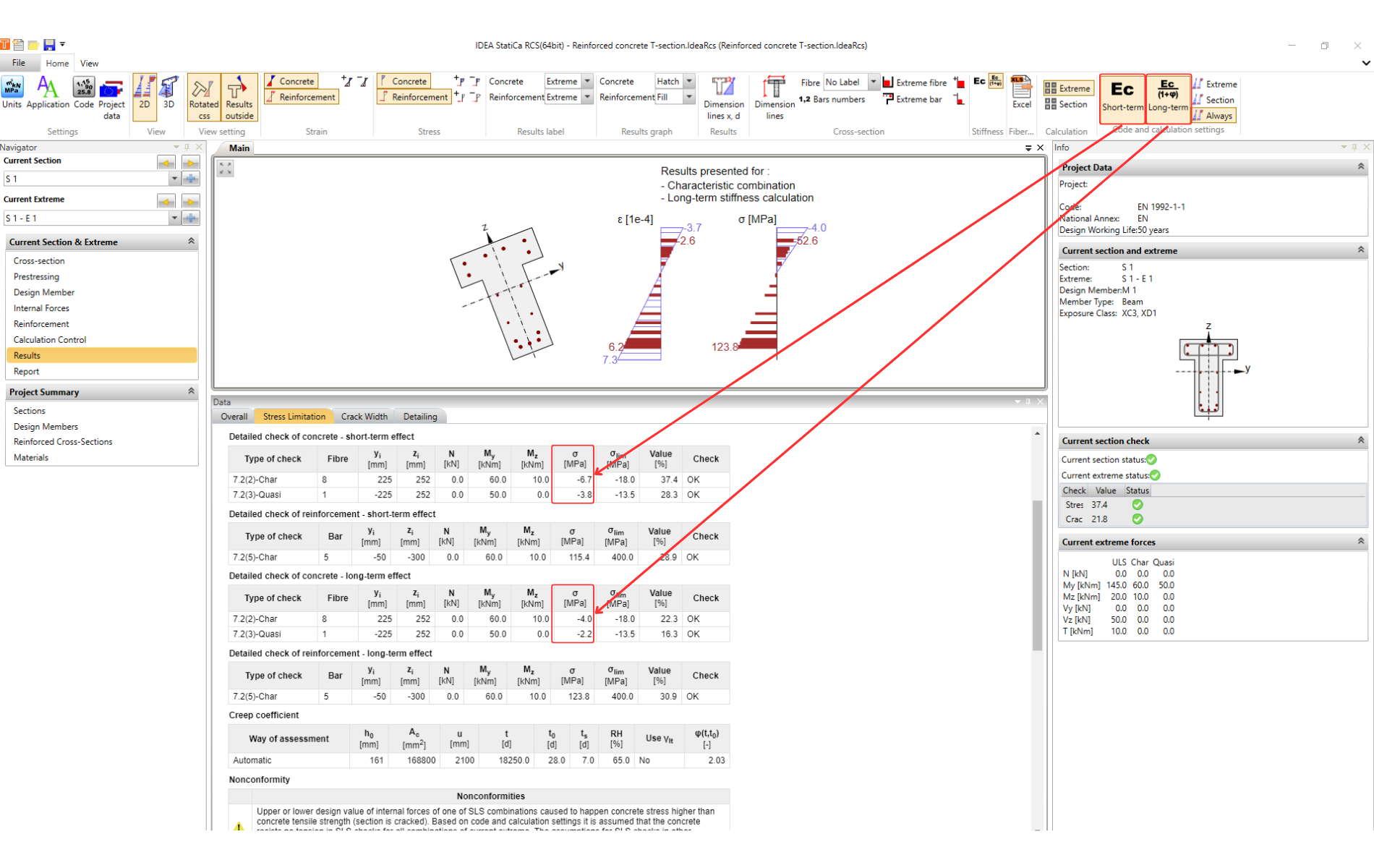
De langetermijneffecten zijn dus opgenomen in de kruip.
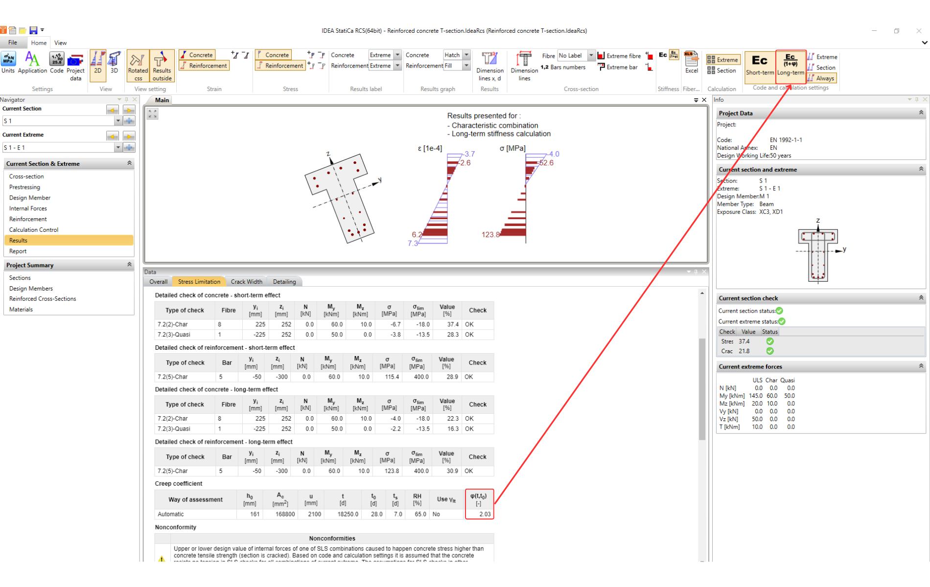
De kruipfactor kan worden berekend door de software (standaardoptie) of kan handmatig worden ingesteld in Ontwerpelement. Houd er rekening mee dat in RCS de lineaire berekening wordt gebruikt voor de kruipfactor.
De normtoetsing wordt uitgevoerd door de berekende spanning in het beton en in de wapening te vergelijken met grenswaarden volgens EN 1992-1-1 7.2.
Tip voor gevorderde gebruikers
Er is een optie om de resultaten te beïnvloeden wanneer de grens wordt overschreden voor 7.2 (3). Het is toegestaan een hogere waarde van de k2-factor te hanteren wanneer de niet-lineaire berekening van de kruipfactor wordt beschouwd.
U kunt de waarde van k2 wijzigen in de Code-instellingen:
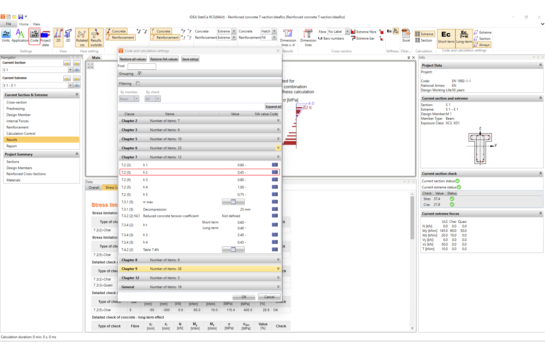
Maar onthoud dat het noodzakelijk is de kruipfactor nauwkeuriger te bepalen.
Laten we de beschikbare opties samenvatten:
- De kruipcoëfficiënt wordt berekend door de software met behulp van lineaire berekening. Dan moet factor k2 = 0,45 (standaard ingesteld) worden gebruikt.
- De kruipcoëfficiënt wordt ingesteld als gebruikersinvoer. Bij het beschouwen van niet-lineaire kruip kan de factor worden verhoogd naar k2 = 0,6.
Scheurwijdte
Als de betonspanning hoger is dan de betonsterkte bij trek, wordt de doorsnede beschouwd als een gescheurde doorsnede. De volgende normtoetsing uit de BGT-toetsing is de scheurwijdte.
Zie de Theoretische achtergrond - Scheuren voor de theorie, aannames en de implementatie van de scheurwijdteberekening in RCS.
Voor een volledig begrip wordt ook aanbevolen het volgende artikel te lezen: Scheurwijdtetoetsing van doorsneden met een grote betondekking.
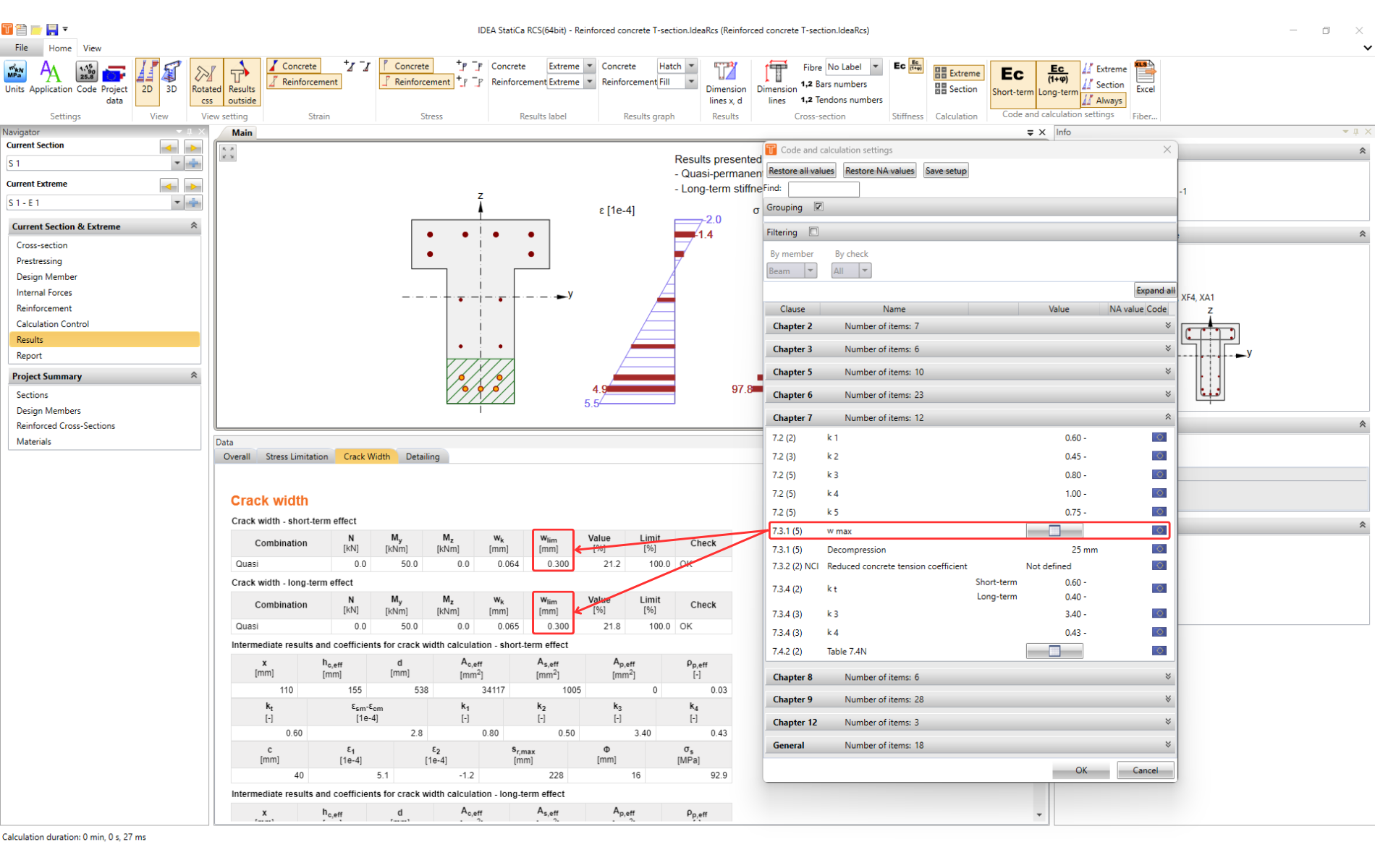
De normtoetsing van de scheurwijdte wordt uitgevoerd door de berekende breedte wk te vergelijken met de breedte wlim volgens 7.3.1 (5).
Geïmplementeerde grenswaarden zijn te vinden in de Code-instellingen.
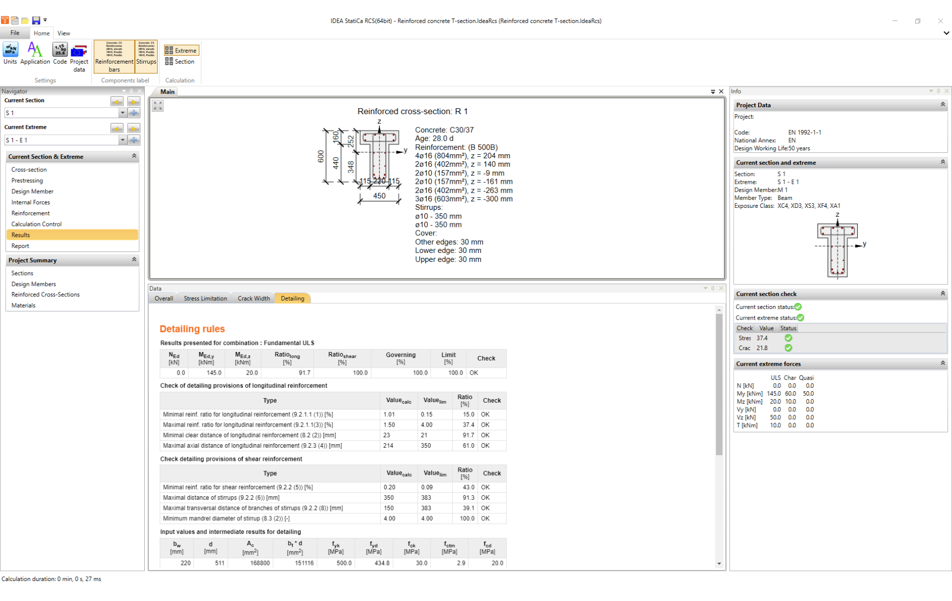
Detaillering
Detaillering is de laatste normtoetsing uit de BGT-toetsingen.
De inwendige krachten waarvoor de toetsing wordt uitgevoerd, worden aan het begin van de tabel vermeld.
Hierna volgen de voorwaarden van de toetsing. Alle zijn ontleend aan de Eurocode. De verwijzing naar het specifieke artikel wordt altijd naast de titel vermeld.
Dit wordt gevolgd door informatie over de waarden die worden gebruikt in de berekening op basis van de invoergegevens.
Tip voor gevorderde gebruikers
Het kan voorkomen dat we, om het ontwerp te versnellen, een vereenvoudigd schema van de wapening invoeren in RCS. In dat geval raden we aan de detaillering uit te schakelen in de berekeningsbesturing en deze handmatig te controleren aan de hand van meer gedetailleerde tekeningen.