Sezioni cave rettangolari
Descrizione
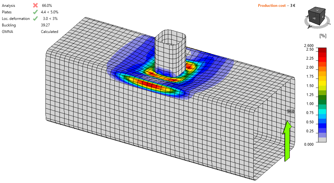
In questo capitolo, vengono verificati mediante CBFEM giunti uniplanari saldati di tipo T, X e K con gap, realizzati con sezioni cave rettangolari e quadrate. Il corrente in sezione cava quadrata (SHS) è saldato direttamente sul corrente in RHS senza l'utilizzo di piastre di rinforzo. I giunti sono caricati da una forza assiale. Nel CBFEM, la resistenza di progetto è limitata dal 5 % di deformazione o da una forza corrispondente a una deformazione del giunto pari a 0,03b0 e nel FMM generalmente dalla deformazione fuori piano della piastra pari a 0,03b0, dove b0 è l'altezza del corrente RHS; si veda Lu et al. (1994).
Metodo dei modi di rottura
Nel caso di giunti T, Y, X o K con gap a carico assiale di sezioni cave rettangolari saldate, possono verificarsi cinque modi di rottura. Questi sono: rottura della faccia del corrente, plastificazione del corrente, rottura della parete laterale del corrente, rottura dell'anima del corrente, rottura a taglio del corrente, rottura a punzonamento e rottura del corrente secondario. In questo studio, vengono esaminati la rottura della faccia del corrente, la rottura del corrente secondario e la rottura a punzonamento per i giunti T, Y e X, mentre per il giunto K con gap vengono esaminati la rottura della faccia del corrente, la rottura a taglio del corrente, la rottura del corrente secondario e la rottura a punzonamento; si veda Fig. 7.2.1. Le saldature progettate secondo EN 1993-1-8:2005 non costituiscono i componenti più deboli del giunto.

\[ \textsf{\textit{\footnotesize{Fig. 7.2.1 Modi di rottura esaminati: a) Rottura della faccia del corrente, b) Rottura a taglio del corrente, c) Rottura del corrente secondario, d) Rottura a punzonamento}}}\]
Rottura della faccia del corrente
La resistenza di progetto della faccia del corrente RHS è determinata dal modello FMM nella sezione 9.5 di EN 1993‑1-8:2020. Il metodo è riportato anche nella ISO/FDIS 14346 ed è descritto in dettaglio in Wardenier et al. (2010). La resistenza di progetto del giunto T, Y o X a carico assiale di sezioni cave rettangolari saldate è
\[ N_{i,Rd} = C_f \frac{f_{y0} t_0^2}{\sin{\theta_i}} \left ( \frac{2 \eta}{(1-\beta) \sin{\theta_i}} + \frac{4}{\sqrt{1-\beta}} \right ) Q_f / \gamma_{M5} \]
La resistenza di progetto del giunto K con gap a carico assiale di sezioni cave rettangolari saldate è
\[ N_{i,Rd} = 8.9 C_f \beta \gamma^{0.5} \frac{f_{y,0} t_0^2}{\sin{\theta_i}} Q_f / \gamma_{M5} \]
dove Cf è il fattore di materiale, fy0 è la tensione di snervamento del corrente, t0 è lo spessore della parete del corrente, η è il rapporto tra l'altezza del corrente secondario e la larghezza del corrente principale, β è il rapporto tra la larghezza del corrente secondario e la larghezza del corrente principale, qi è l'angolo compreso tra il corrente secondario i e il corrente principale (i = 1, 2), Qf è la funzione di tensione del corrente e γ è il rapporto di snellezza del corrente.
Rottura del corrente secondario
La resistenza di progetto della faccia del corrente RHS può essere determinata utilizzando il metodo fornito dal modello FMM nella sezione 9.5 di EN 1993-1-8:2020. La resistenza di progetto del giunto T, Y o X a carico assiale di sezioni cave rettangolari saldate è
\[ N_{i,Rd} = C_f f_{yi} t_i (2 h_i - 4 t_i + 2 b_{eff} ) / \gamma_{M5} \]
La resistenza di progetto del giunto K con gap a carico assiale di sezioni cave rettangolari saldate è
\[ N_{i,Rd} = C_f f_{yi} t_i (2 h_i - 4 t_i + b_i + b_{eff} ) / \gamma_{M5} \]
dove Cf è il fattore di materiale, fyi è la tensione di snervamento del corrente secondario i (i = 1, 2), ti è lo spessore della parete del corrente secondario i, hi è l'altezza del corrente secondario i, bi è la larghezza del corrente secondario i, beff è la larghezza efficace del corrente secondario.
Punzonamento
La resistenza di progetto del giunto T, Y o X a carico assiale di sezioni cave rettangolari saldate è
\[ N_{i,Rd} = C_f \frac{f_{y0} t_0}{\sqrt{3}\sin{\theta_i}} \left( \frac{2h_i}{\sin{\theta_i}} + 2b_{e,p} \right ) / \gamma_{M5} \]
La resistenza di progetto del giunto K con gap a carico assiale di sezioni cave rettangolari saldate è
\[ N_{i,Rd} = C_f \frac{f_{y0} t_0}{\sqrt{3}\sin{\theta_i}} \left( \frac{2h_i}{\sin{\theta_i}} + b_i+b_{e,p} \right ) / \gamma_{M5} \]
Dove Cf è il fattore di materiale, fy0 è la tensione di snervamento del corrente, t0 è lo spessore della parete del corrente, qi è l'angolo compreso tra il corrente secondario i e il corrente principale (i = 1, 2), hi è l'altezza del corrente secondario i, bi è la larghezza del corrente secondario i e be,p è la larghezza efficace per il punzonamento.
Rottura a taglio del corrente
La resistenza di progetto del giunto K con gap a carico assiale di sezioni cave rettangolari saldate è
\[ N_{i,Rd} = \frac{f_{y0}A_{V,0,gap}}{\sqrt{3}\sin{\theta_i}}/\gamma_{M5} \]
dove fy0 è la tensione di snervamento del corrente, Av,0,gap è l'area efficace per la rottura a taglio del corrente e qi è l'angolo compreso tra il corrente secondario i e il corrente principale (i = 1, 2).
Campo di validità
Il CBFEM è stato verificato per giunti tipici T, Y, X e K con gap di sezioni cave rettangolari saldate. Il campo di validità per questi giunti è definito nella Tabella 9.2 della prEN 1993-1-8:2020; si veda Tab. 7.2.1. Lo stesso campo di validità è applicato al modello CBFEM. Al di fuori del campo di validità del FMM, è necessario predisporre una sperimentazione per la validazione o eseguire una verifica secondo un modello di ricerca validato.
Tab. 7.2.1 Campo di validità per il metodo dei modi di rottura, Tabella 9.2 di EN 1993-1-8:2020
| Generale | \(0.2 \le \frac{d_i}{d_0} \le 1.0 \) | \( \theta_i \ge 30^{\circ} \) | \(\frac{e}{d_0} \le 0.25 \) |
| \(g \ge t_1+t_2 \) | \(f_{yi} \le f_{y0} \) | \( t_i \le t_0 \) |
| Corrente | Compressione | Classe 1 o 2 e \( d_0 / t_0 \le 50 \) (ma per giunti X: \( d_0/t_0 \le 40 \)) |
| Trazione | \(d_0 / t_0 \le 50 \) (ma per giunti X: \( d_0/t_0 \le 40 \)) | |
| Correnti secondari CHS | Compressione | Classe 1 o 2 e \(b_i / t_i \le 35\) e \(\frac{h_i}{t_i} \le 35 \) |
| Trazione | \(b_i / t_i \le 35\) e \(\frac{h_i}{t_i} \le 35 \) |
7.2.2 Giunto uniplanare T e Y-SHS
Una panoramica degli esempi considerati è riportata nella Tab. 7.2.2. I casi selezionati coprono un ampio intervallo di rapporti geometrici del giunto. La geometria dei giunti con le relative dimensioni è mostrata in Fig. 7.2.2. I giunti selezionati hanno raggiunto la rottura secondo il metodo basato sul FMM per rottura della faccia del corrente o rottura del corrente secondario.
Tab. 7.2.2 Panoramica degli esempi
| Esempio | Corrente principale | Corrente secondario | Angoli | Materiale | ||
| Sezione | Sezione | θ1 | fy | fu | E | |
| [°] | [MPa] | [MPa] | [GPa] | |||
| 1 | SHS200/6.3 | SHS90/8.0 | 90 | 355 | 490 | 210 |
| 2 | SHS200/8.0 | SHS90/8.0 | 90 | 355 | 490 | 210 |
| 3 | SHS200/12.5 | SHS120/12.5 | 90 | 355 | 490 | 210 |
| 4 | SHS200/6.3 | SHS140/12.5 | 60 | 355 | 490 | 210 |
| 5 | SHS200/8.0 | SHS80/8.0 | 60 | 355 | 490 | 210 |
| 6 | SHS200/10.0 | SHS120/12.5 | 60 | 355 | 490 | 210 |
| 7 | SHS200/12.5 | SHS90/8.0 | 60 | 355 | 490 | 210 |
| 8 | SHS200/6.3 | SHS100/10.0 | 30 | 355 | 490 | 210 |
| 9 | SHS200/8.0 | SHS150/16.0 | 30 | 355 | 490 | 210 |
| 10 | SHS200/10.0 | SHS100/10.0 | 30 | 355 | 490 | 210 |
| 11 | SHS200/12.5 | SHS100/10.0 | 30 | 355 | 490 | 210 |

\[ \textsf{\textit{\footnotesize{Fig. 7.2.2 Dimensioni del giunto T}}}\]
Verifica della resistenza
I risultati del FMM sono confrontati con i risultati del CBFEM. Il confronto è incentrato sulla resistenza e sul modo di rottura di progetto. I risultati sono presentati nella Tab. 7.2.3.
Tab. 7.2.3 Confronto dei risultati delle resistenze di progetto a trazione/compressione previste da CBFEM e FMM
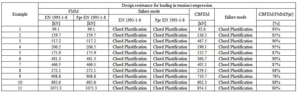
Lo studio mostra una buona concordanza per i casi di carico applicati. I risultati sono riassunti in un diagramma che confronta le resistenze di progetto di CBFEM e FMM; si veda Fig. 7.2.3. I risultati mostrano che la differenza tra i due metodi di calcolo è in tutti i casi inferiore al 10 %.
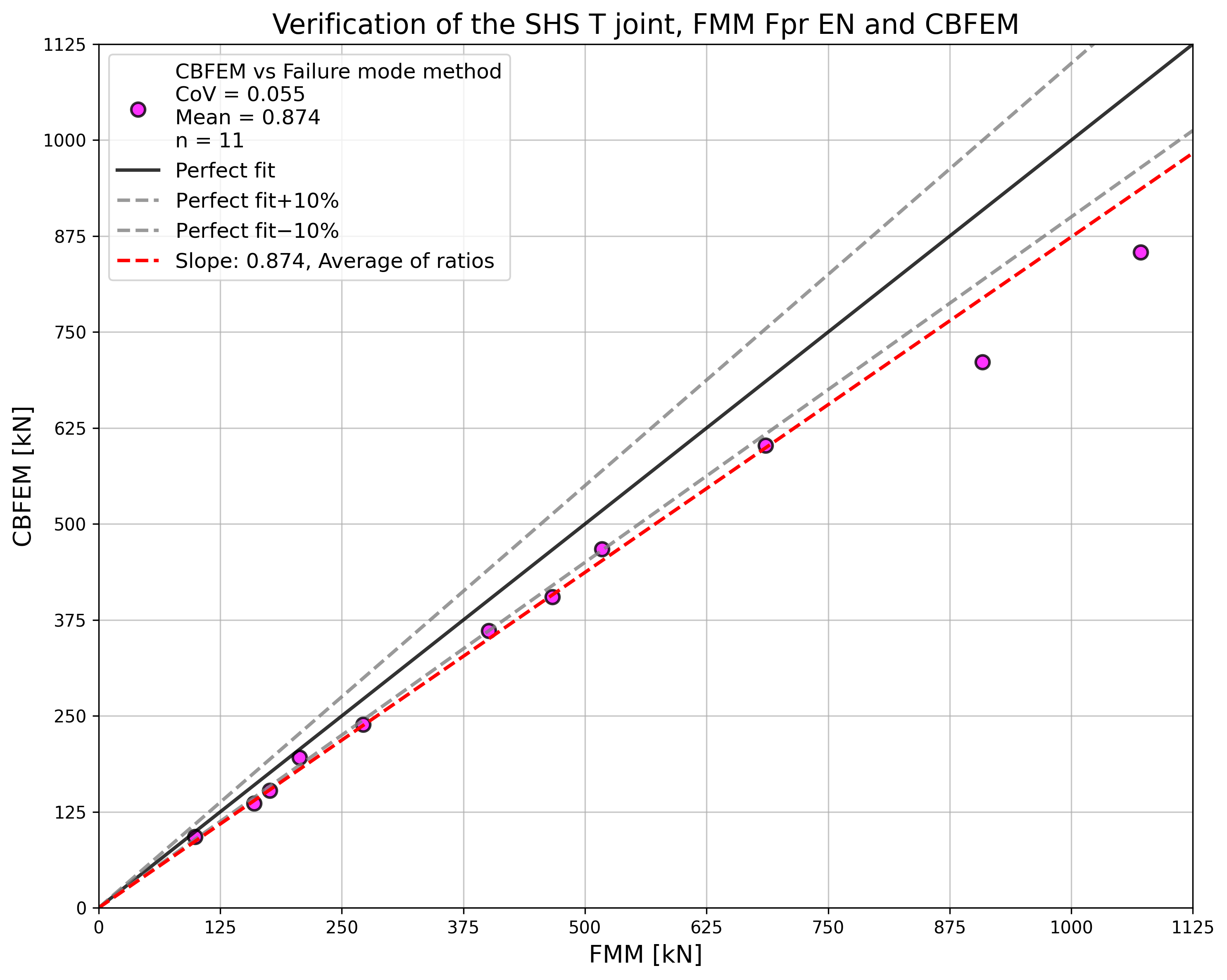
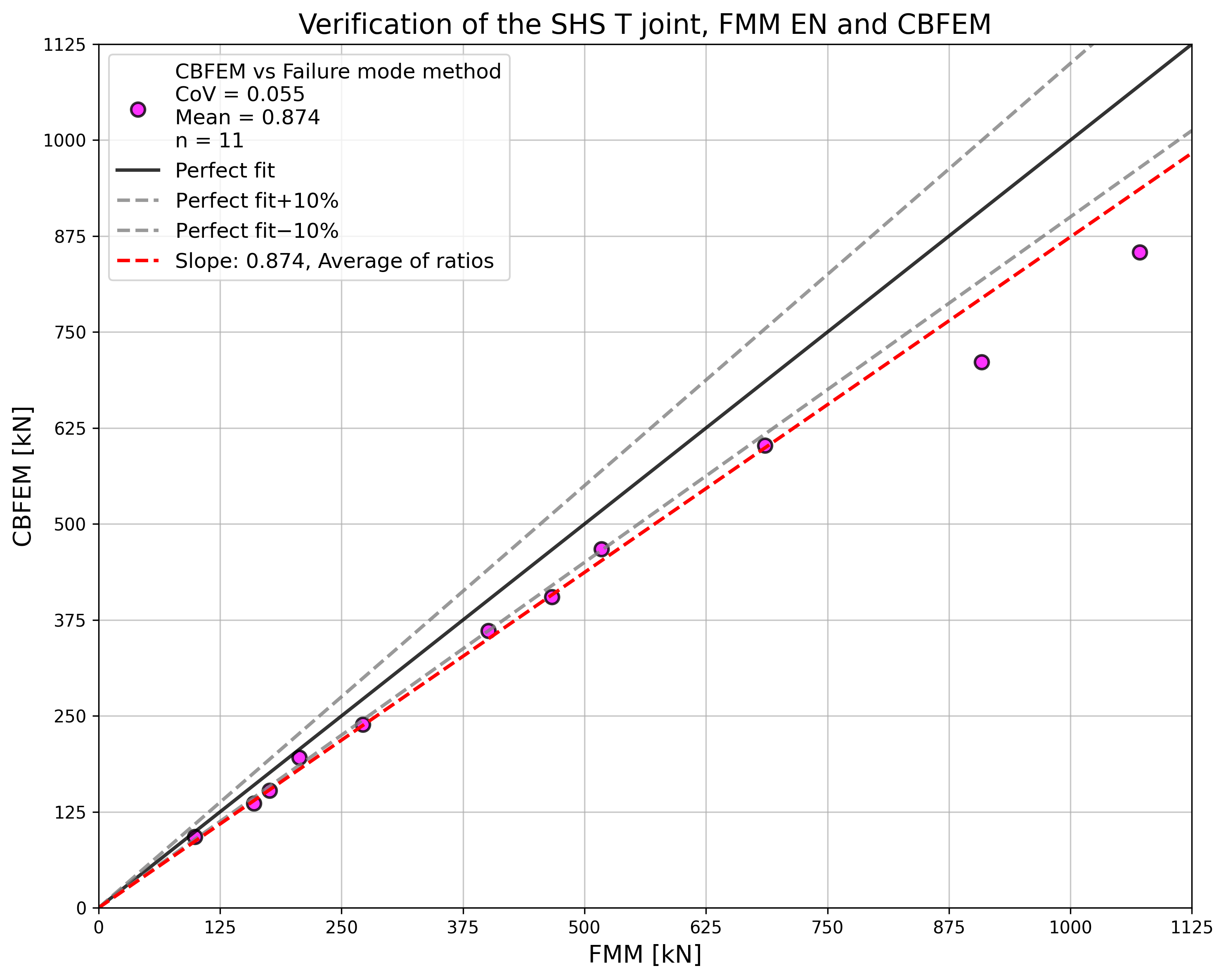
\[ \textsf{\textit{\footnotesize{Fig. 7.2.3 Verifica della resistenza determinata da CBFEM rispetto a FMM per il giunto uniplanare SHS T e Y}}}\]
Esempio di riferimento
Dati di input
Corrente principale
- Acciaio S355
- Sezione SHS 200×200×6.3
Corrente secondario
- Acciaio S355
- Sezione SHS 90×90×8.0
- Angolo tra il corrente secondario e il corrente principale 90°
Saldatura
- Saldatura di testa
Dimensione della rete
- 16 elementi sulla parete più grande dell'elemento cavo rettangolare
Carico applicato
- Forza sul corrente secondario in compressione/trazione
Risultati
- La resistenza di progetto a compressione/trazione è NRd = 92.6 kN
- Il modo di rottura di progetto è la rottura della faccia del corrente
Giunto uniplanare X-SHS
Una panoramica degli esempi considerati è riportata nella Tab. 7.2.4. I casi selezionati coprono un ampio intervallo di rapporti geometrici del giunto. I giunti selezionati hanno raggiunto la rottura secondo il metodo basato sul FMM per rottura della faccia del corrente o rottura del corrente secondario.
Tab. 7.2.4 Panoramica degli esempi
| Esempio | Corrente principale | Corrente secondario | Angoli | Materiale | ||
| Sezione | Sezione | θ | fy | fu | E | |
| [°] | [MPa] | [MPa] | [GPa] | |||
| 1 | SHS200/6.3 | SHS140/12.5 | 90 | 355 | 490 | 210 |
| 2 | SHS200/8.0 | SHS70/8.0 | 90 | 355 | 490 | 210 |
| 3 | SHS200/10.0 | SHS120/12.5 | 90 | 355 | 490 | 210 |
| 4 | SHS200/12.5 | SHS90/8.0 | 90 | 355 | 490 | 210 |
| 5 | SHS200/6.3 | SHS90/8.0 | 60 | 355 | 490 | 210 |
| 6 | SHS200/8.0 | SHS80/8.0 | 60 | 355 | 490 | 210 |
| 7 | SHS200/10.0 | SHS150/6.3 | 60 | 355 | 490 | 210 |
| 8 | SHS200/12.5 | SHS140/12.5 | 60 | 355 | 490 | 210 |
| 9 | SHS200/16.0 | SHS120/12.5 | 60 | 355 | 490 | 210 |
| 10 | SHS200/6.3 | SHS100/8.0 | 30 | 355 | 490 | 210 |
| 11 | SHS200/8.0 | SHS150/16.0 | 30 | 355 | 490 | 210 |
| 12 | SHS200/10.0 | SHS100/10.0 | 30 | 355 | 490 | 210 |
| 13 | SHS200/16.0 | SHS90/8.0 | 30 | 355 | 490 | 210 |
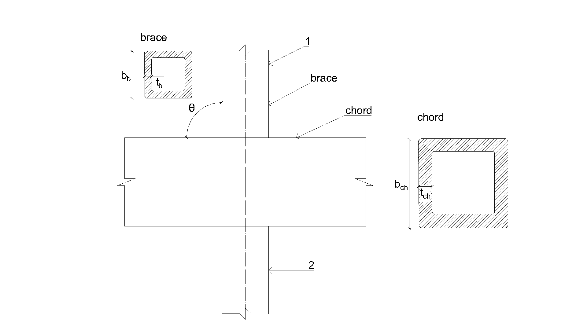
\[ \textsf{\textit{\footnotesize{Fig. 7.2.4 Dimensioni del giunto X}}}\]
Verifica della resistenza
I risultati del metodo basato sui modi di rottura (FMM) sono confrontati con i risultati del CBFEM. Il confronto è incentrato sulla resistenza e sul modo di rottura di progetto; si veda Tab. 7.2.5.
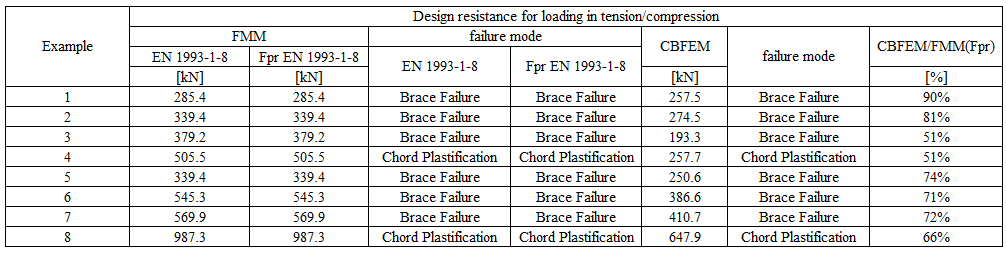
Tab. 7.2.5 Confronto dei risultati della previsione della resistenza da CBFEM e FMM

Lo studio mostra una buona concordanza per i casi di carico applicati. I risultati sono riassunti in un diagramma che confronta le resistenze di progetto di CBFEM e FMM; si veda Fig. 7.2.4. I risultati mostrano che la differenza tra i due metodi di calcolo è in tutti i casi inferiore al 13 %.
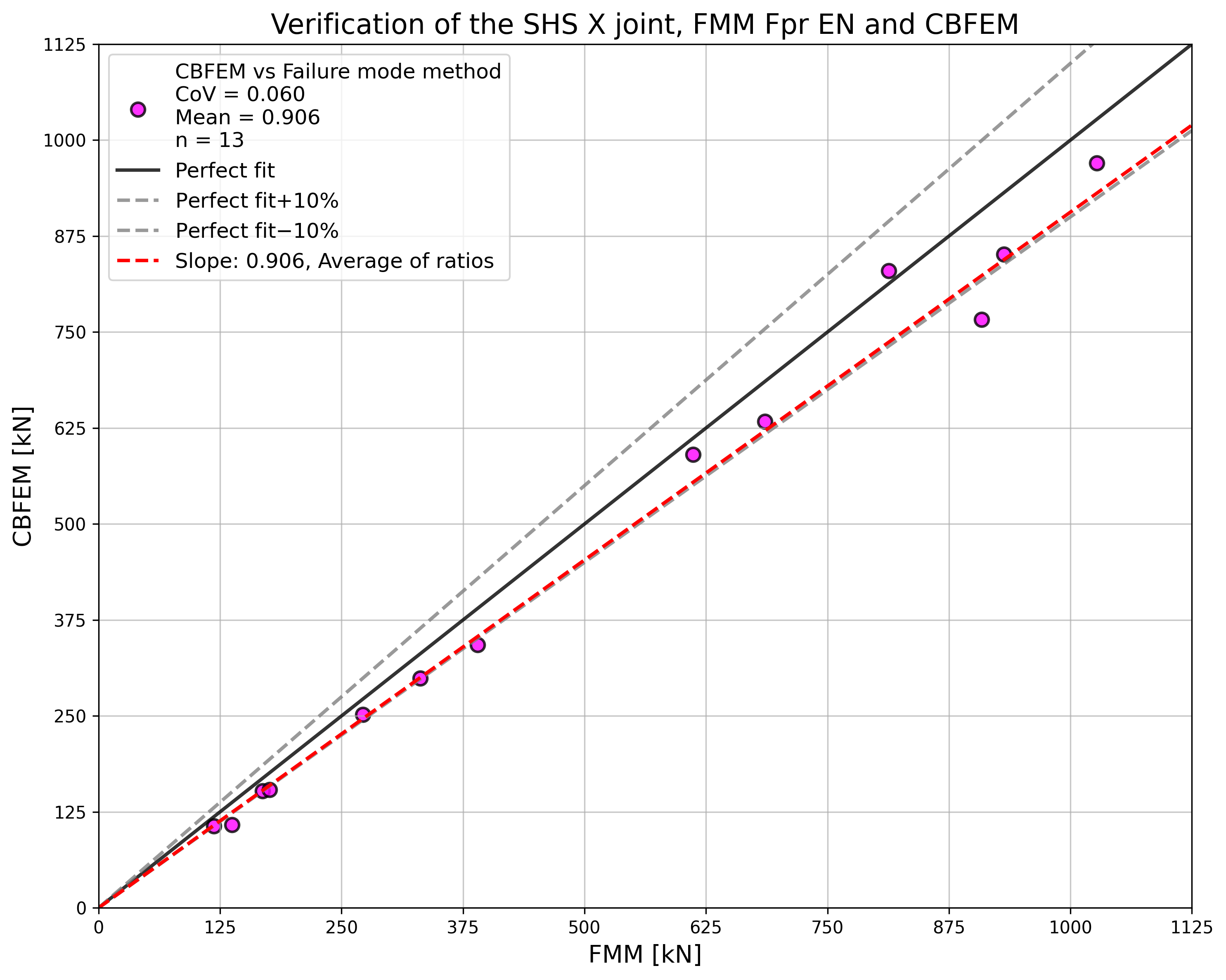

\[ \textsf{\textit{\footnotesize{Fig. 7.2.5 Verifica della resistenza determinata da CBFEM rispetto a FMM per il giunto uniplanare SHS X}}}\]
Esempio di riferimento
Dati di input
Corrente principale
- Acciaio S355
- Sezione SHS 200×200×6,3
Correnti secondari
- Acciaio S355
- Sezioni SHS 140×140×12,5
- Angolo tra i correnti secondari e il corrente principale 90°
Saldature
- Saldature di testa
Dimensione della rete
- 16 elementi sulla parete più grande dell'elemento cavo rettangolare
Carico applicato
- Forza sul corrente secondario in compressione/trazione
Risultati
- La resistenza di progetto a compressione/trazione è NRd = 152.4 kN
- Il modo di rottura di progetto è la rottura della faccia del corrente
7.2.4 Giunto uniplanare K-SHS
Una panoramica degli esempi considerati è riportata nella Tab. 7.2.6. I casi selezionati coprono un ampio intervallo di rapporti geometrici del giunto. I giunti selezionati hanno raggiunto la rottura secondo il metodo basato sul FMM per rottura della faccia del corrente o rottura del corrente secondario.
Tab. 7.2.6 Panoramica degli esempi
| Esempio | Corrente principale | Correnti secondari | Angoli | Materiale | ||
| Sezione | Sezioni | θ | fy | fu | E | |
| [°] | [MPa] | [MPa] | [GPa] | |||
| 1 | SHS180/10.0 | SHS70/3.0 | 45 | 355 | 490 | 210 |
| 2 | SHS180/10.0 | SHS70/3.6 | 45 | 355 | 490 | 210 |
| 3 | SHS200/8.0 | SHS80/3.6 | 45 | 355 | 490 | 210 |
| 4 | SHS200/8.0 | SHS100/10.0 | 45 | 355 | 490 | 210 |
| 5 | SHS200/200/10.0 | SHS70/3.6 | 45 | 355 | 490 | 210 |
| 6 | SHS200/200/10.0 | SHS100/4.0 | 45 | 355 | 490 | 210 |
| 7 | SHS200/200/12.5 | SHS70/6.3 | 45 | 355 | 490 | 210 |
| 8 | SHS200/200/12.5 | SHS100/8.0 | 45 | 355 | 490 | 210 |
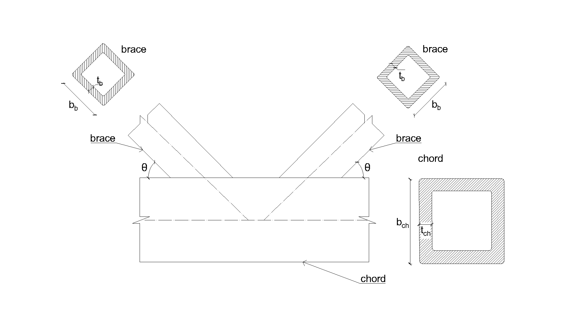
\[ \textsf{\textit{\footnotesize{Fig. 7.2.6 Dimensioni del giunto K}}}\]
Verifica
I risultati del CBFEM sono confrontati con i risultati del FMM. Il confronto è incentrato sulla resistenza e sul modo di rottura di progetto. I risultati sono presentati nella Tab. 7.2.7.
Tab. 7.2.7 Confronto dei risultati della previsione delle resistenze da CBFEM e FMM
Lo studio mostra una buona concordanza per i casi di carico applicati. I risultati sono riassunti in un diagramma che confronta le resistenze di progetto di CBFEM e FMM; si veda Fig. 7.2.5. I risultati mostrano che il CBFEM è conservativo in tutti i casi rispetto al FMM.
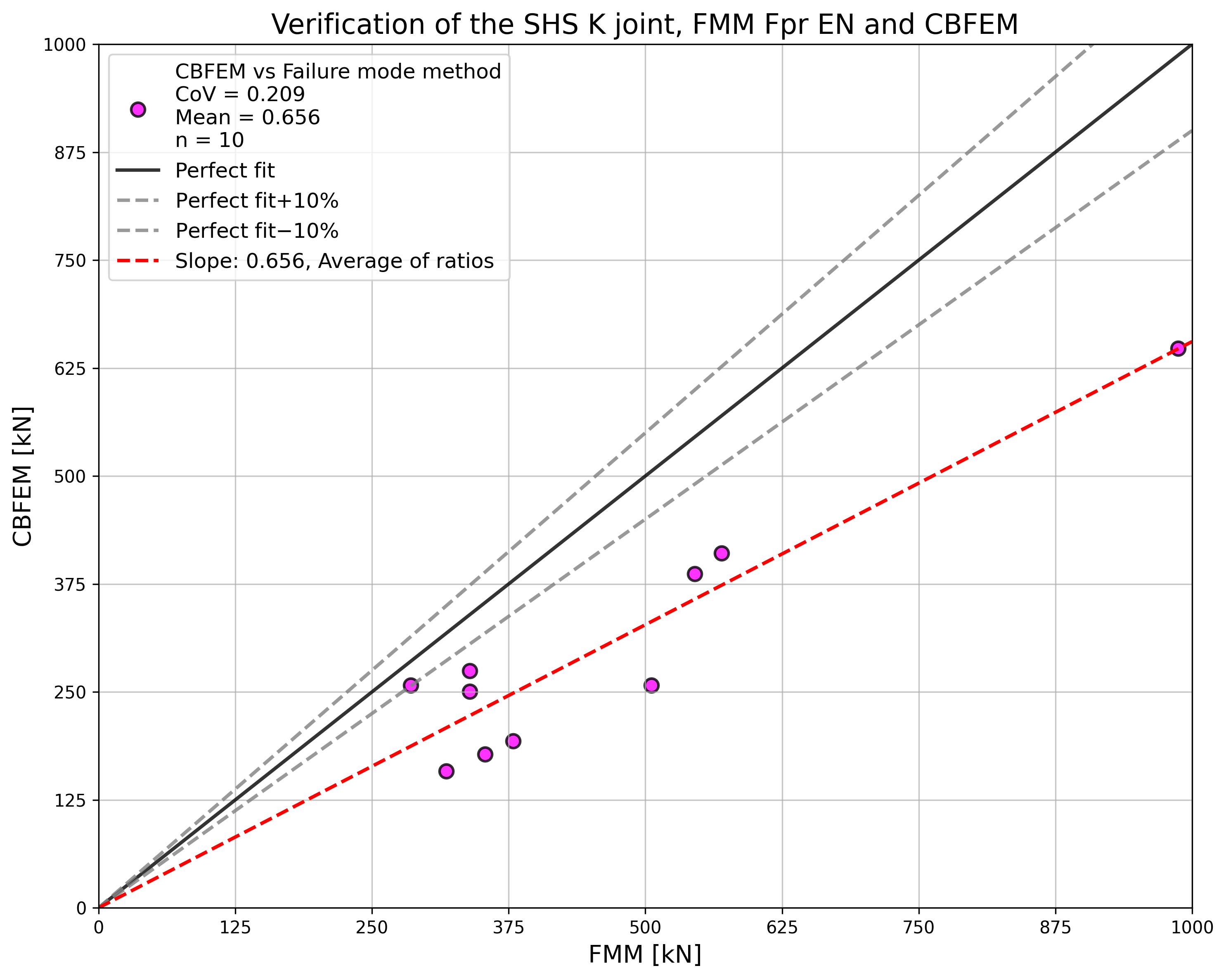
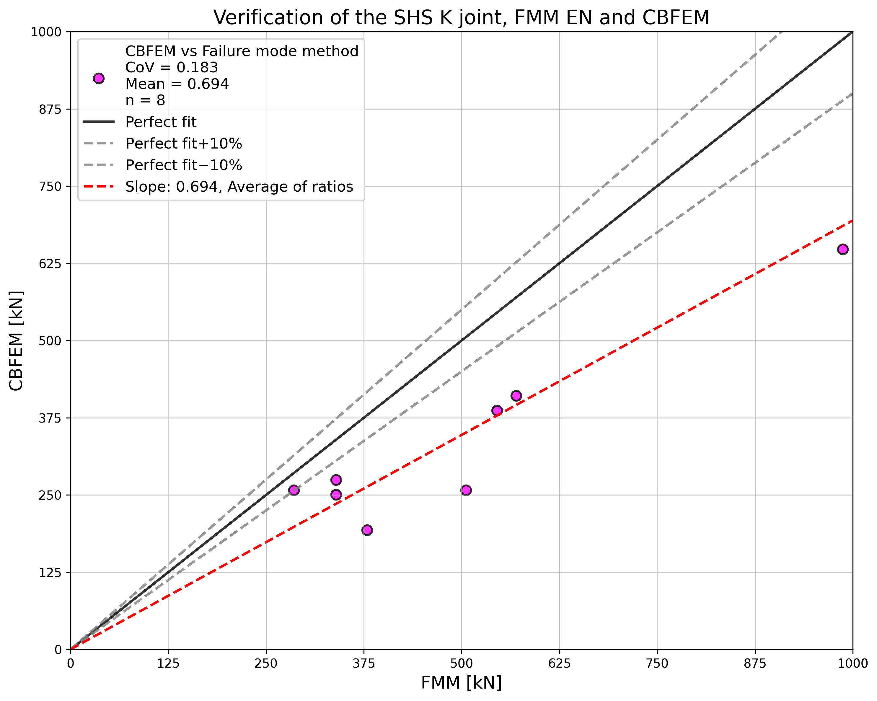
\[ \Fig. 7.2.7 Verifica della resistenza determinata da CBFEM rispetto a FMM per il giunto uniplanare SHS K}}}\]
Esempio di riferimento
Dati di input
Corrente principale
- Acciaio S355
- Sezione SHS 180×180×10,0
Correnti secondari
- Acciaio S355
- Sezioni SHS 70×70×3,0
- Angolo tra i correnti secondari e il corrente principale 45°
Saldature
- Saldature di testa
Dimensione della rete
- 16 elementi sulla parete più grande dell'elemento cavo rettangolare
Carico applicato
- Forza sul corrente secondario in compressione/trazione
Risultati
- La resistenza di progetto a compressione/trazione è NRd = 257.5 kN
- Il modo di rottura di progetto è la rottura della faccia del corrente