
Progettazione strutturale di una fondazione con diagonale (EN)
1 Nuovo progetto
Avviamo IDEA StatiCa e selezioniamo l'applicazione Connection. Creare un nuovo progetto selezionando il modello parametrico più vicino al progetto desiderato, inserendo il nome e scegliendo il codice di progetto e le proprietà dei materiali predefinite – S 235.

2 Geometria
Una colonna e una piastra di base con ancoraggi sono stati aggiunti automaticamente.
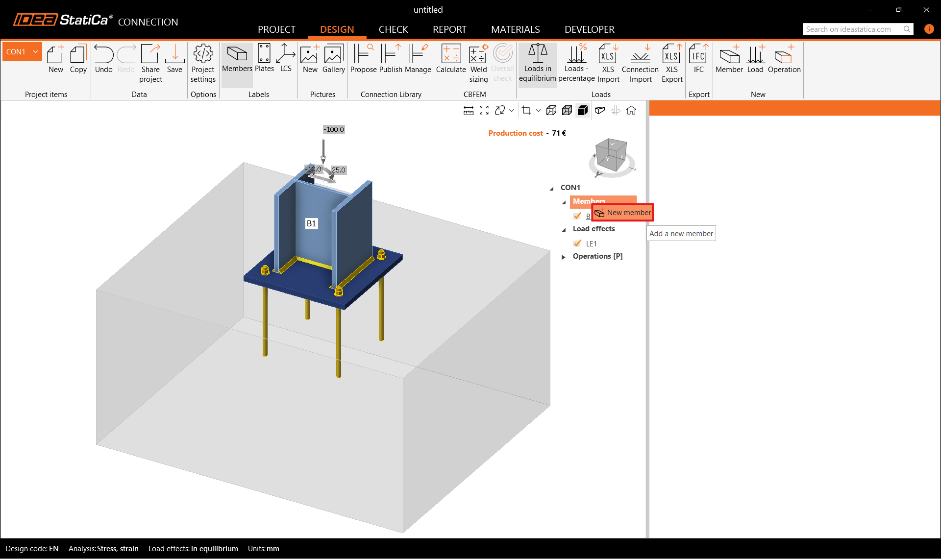
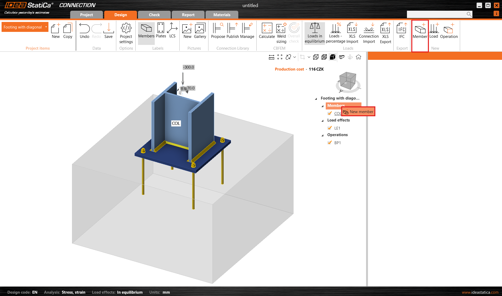
Aggiungere un nuovo elemento. È possibile utilizzare il pulsante Elemento nella barra multifunzione superiore oppure fare clic con il tasto destro del mouse sugli Elementi nell'albero del navigatore.
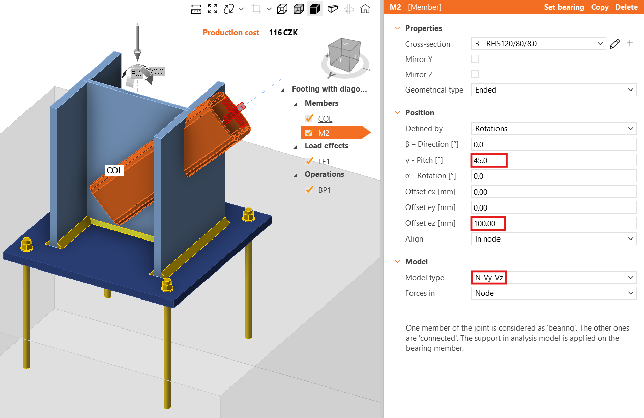
E modificare la sua sezione trasversale in RHS120/80/8.0.

Modificare l'inclinazione dell'elemento e il valore dell'offset ez. Impostare il tipo di modello su N-Vy-Vz poiché questo elemento è in grado di trasferire solo forze assiali; in caso contrario potrebbe verificarsi un meccanismo/singolarità o l'analisi potrebbe non convergere.
Per ulteriori informazioni sul tipo di modello, vedere qui.
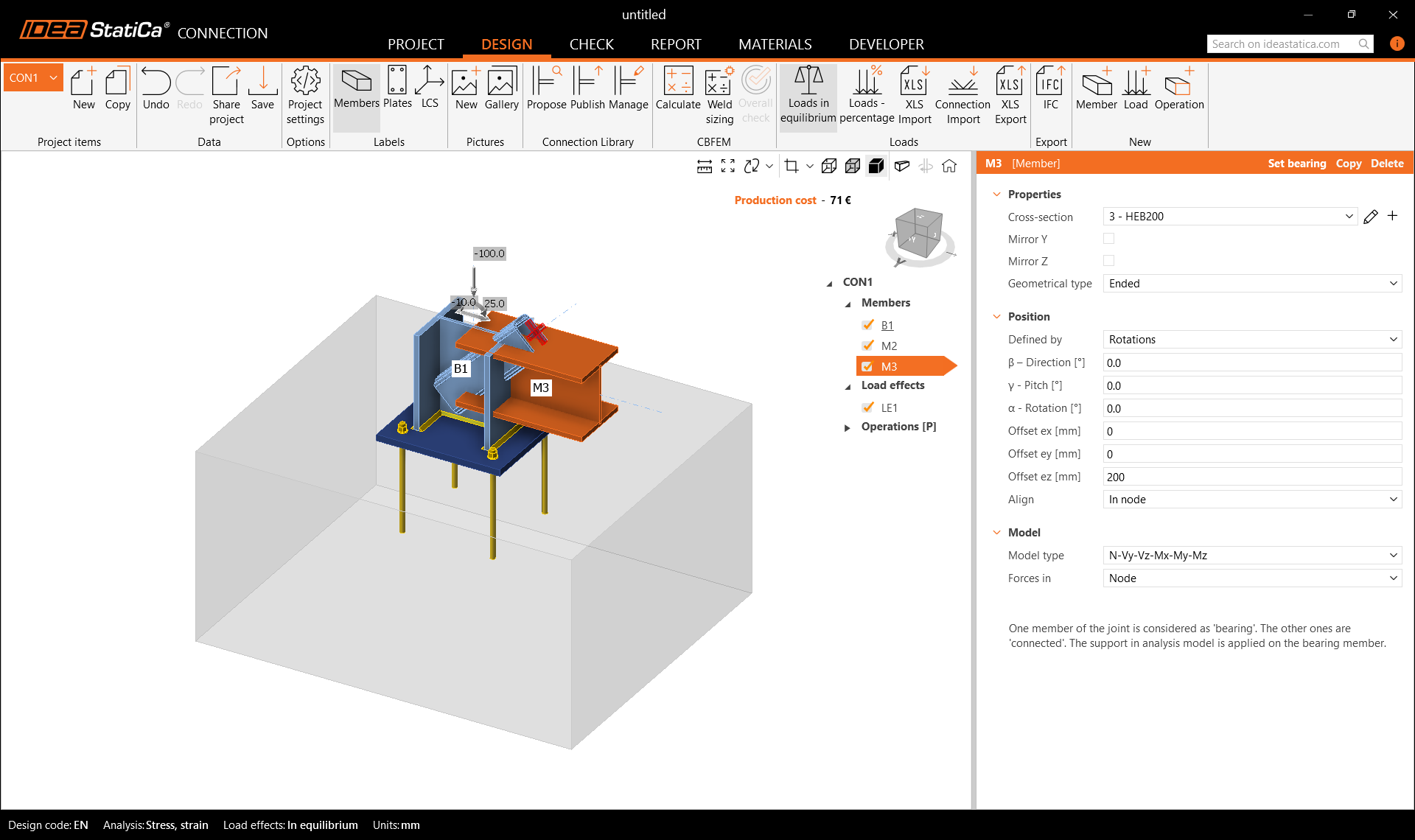
Aggiungere un altro elemento e modificarne la sezione trasversale.

Quindi modificarne le proprietà.

Verificare la geometria dell'intero modello.
3 Effetti del carico
Un effetto del carico è stato aggiunto automaticamente. Inserire i valori delle forze interne nella tabella. È possibile aggiungere ulteriori combinazioni di carico.

4 Progettazione
L'operazione di produzione Piastra di base è definita nel modello parametrico; pertanto è possibile modificarne le proprietà direttamente nella scheda Operazioni.
È anche possibile Esplodere il modello parametrico e utilizzare invece l'operazione di produzione.

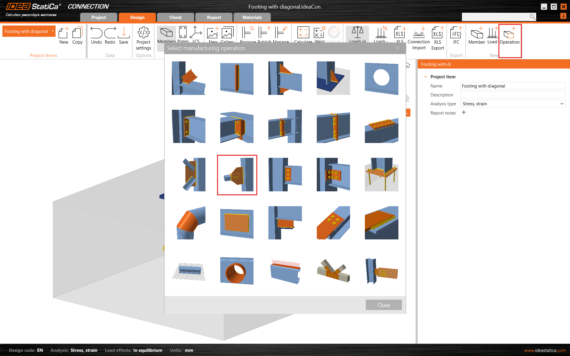
Procedere aggiungendo un'altra operazione di produzione e selezionare la Piastra d'estremità.

Modificare le proprietà dell'operazione EP1.

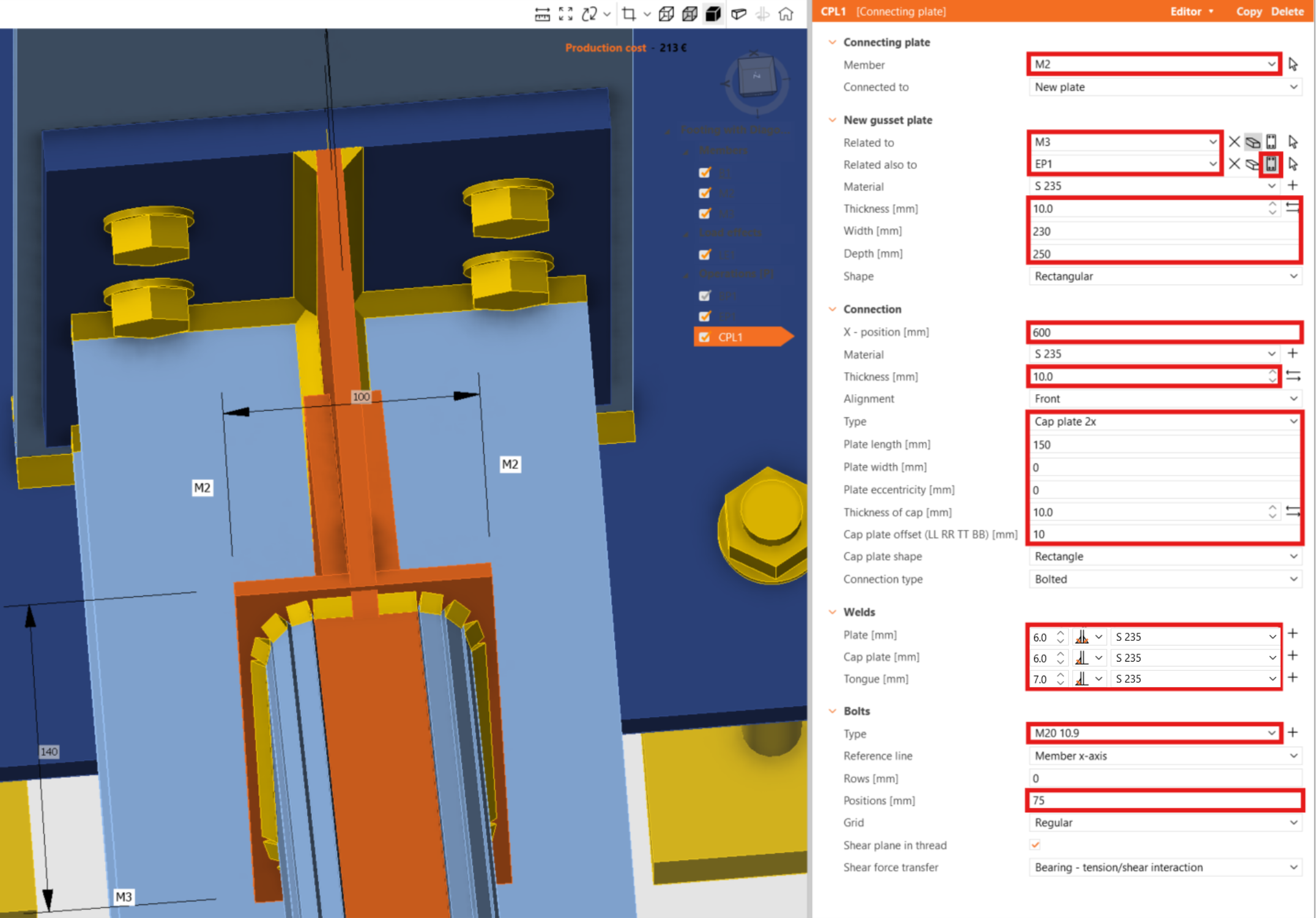
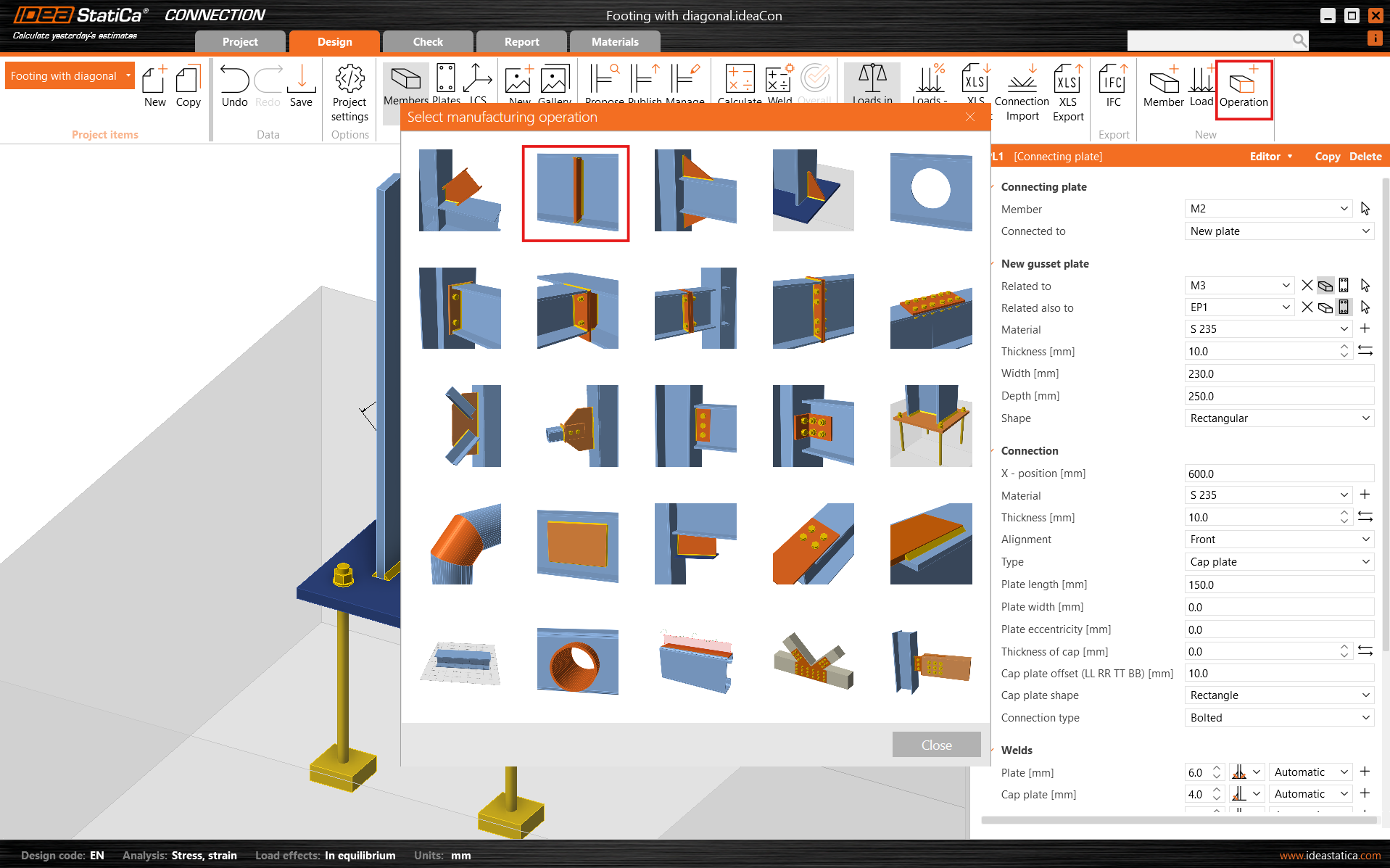
Ora aggiungere la Piastra di collegamento.
E ridefinirne le proprietà.
Nell'angolo in alto a sinistra è possibile visualizzare i messaggi di avviso relativi alle interferenze tra piastre e saldature. Inoltre, attivando la modalità di visualizzazione Trasparente, le aree di interferenza vengono evidenziate nella finestra grafica 3D.
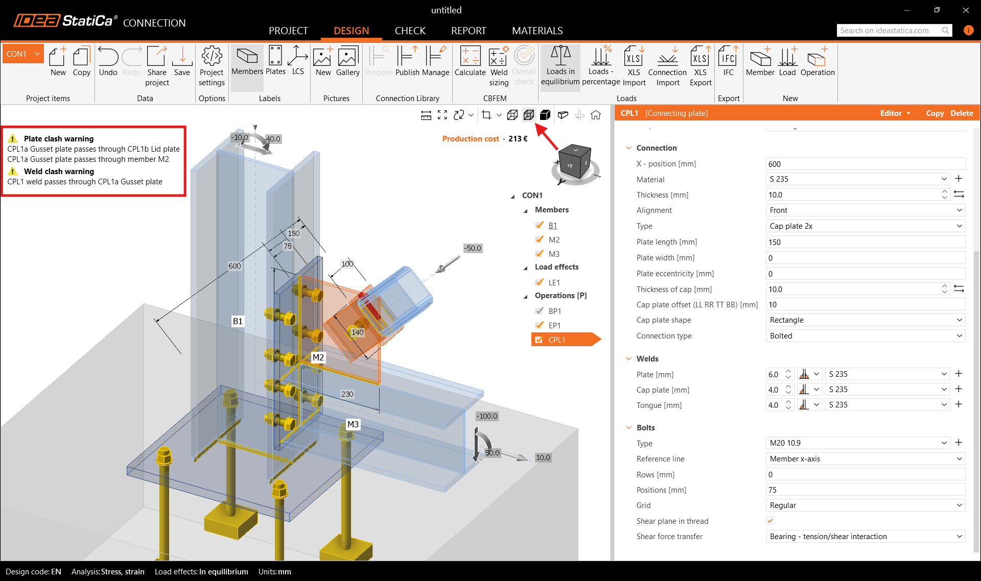
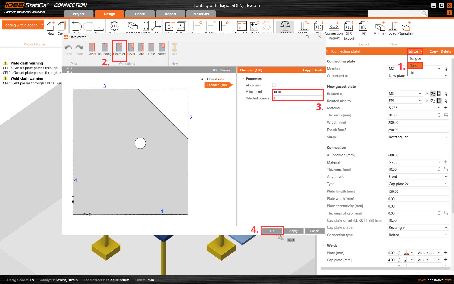
Per eliminare le interferenze tra piastre e saldature, tagliare un angolo della piastra di collegamento CPL1. A tale scopo, accedere all'Editor - Piastra di nodo oppure fare clic con il tasto destro del mouse sulla piastra di nodo e creare uno Smusso all'angolo numero 2.
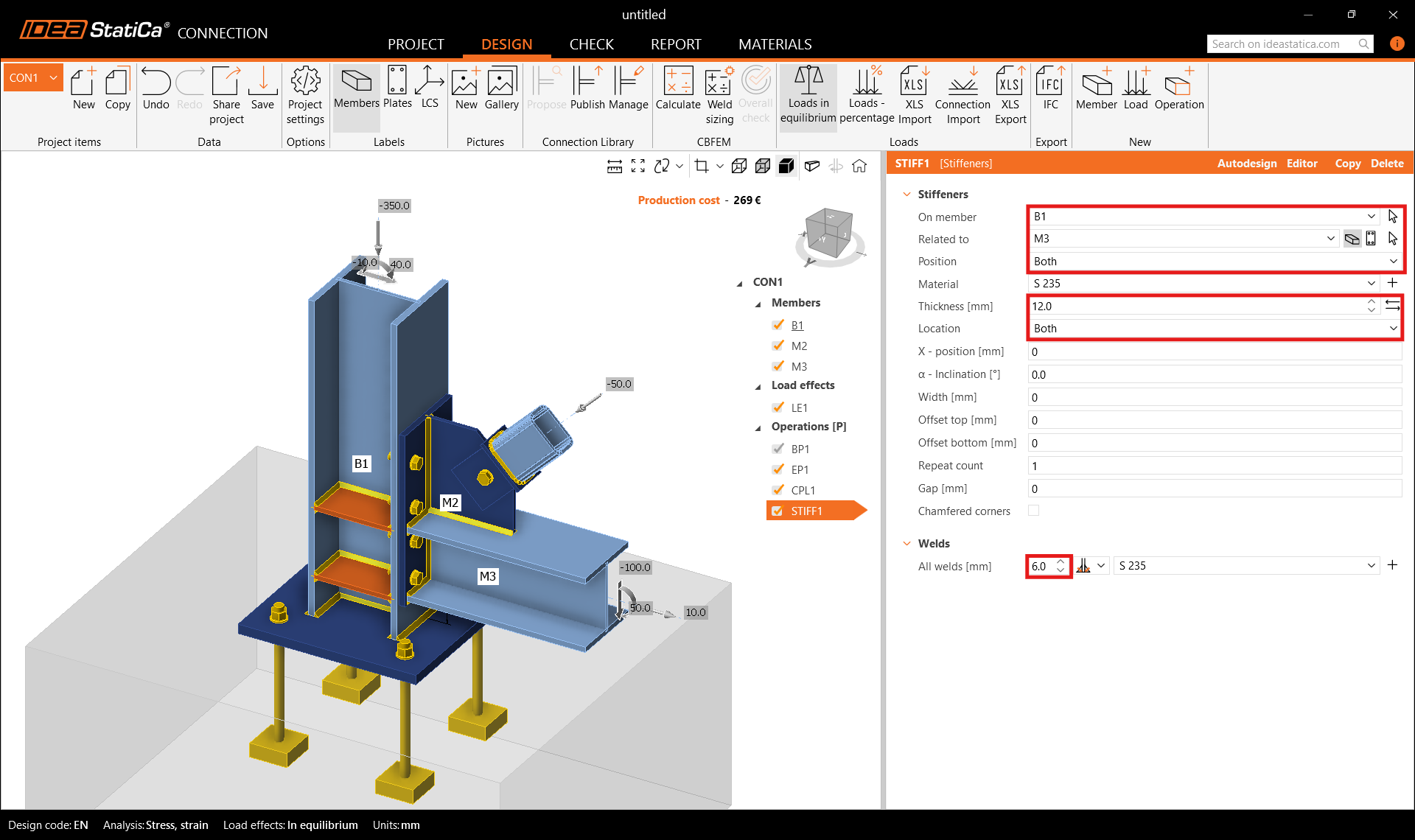
Completare la progettazione con l'operazione Irrigidimento.
E impostare le proprietà corrette di STIFF1.
Verifichiamo il progetto finale del giunto.

5 Verifica
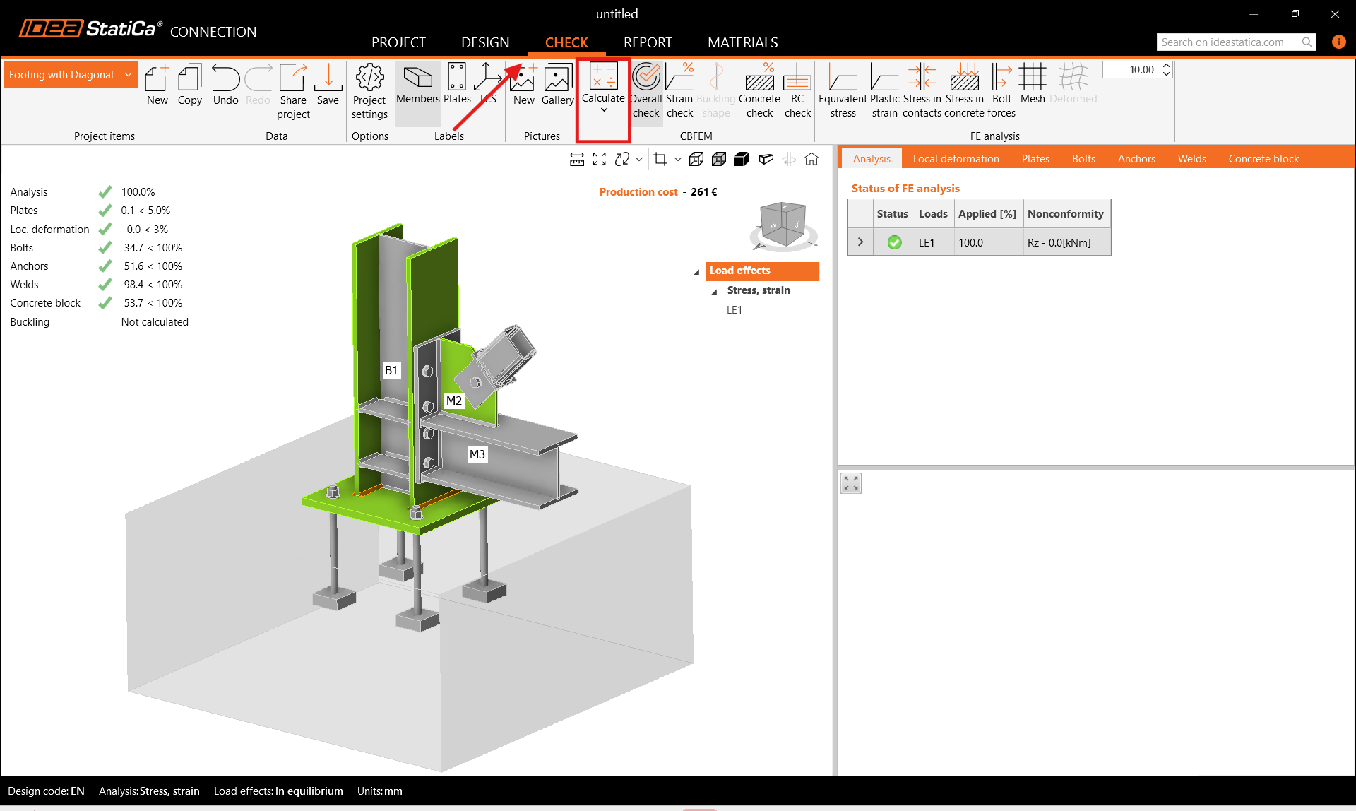
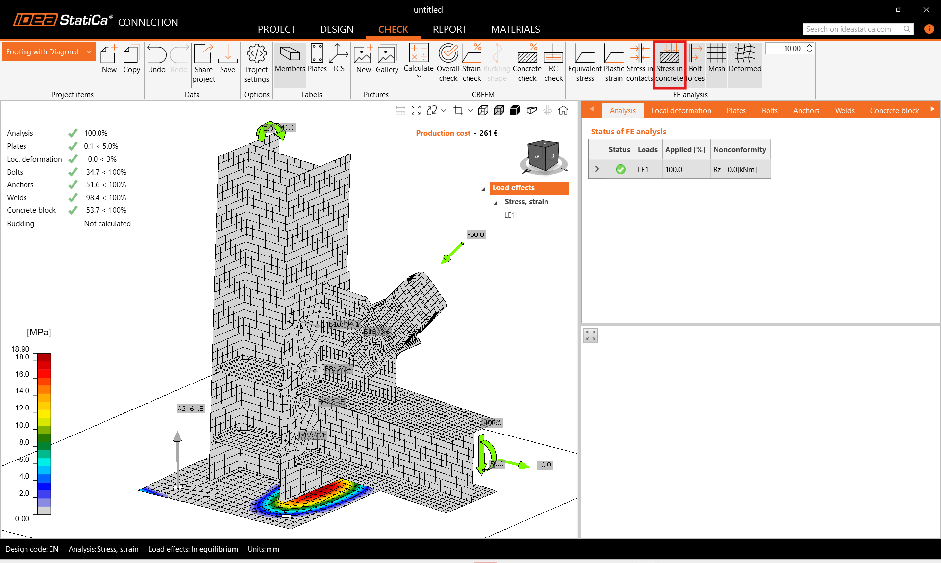
Avviare l'analisi facendo clic su Calcola nella barra multifunzione. Il modello di analisi viene generato automaticamente, il calcolo basato su CBFEM viene eseguito e si può visualizzare la verifica complessiva insieme ai valori di base dei risultati della verifica.
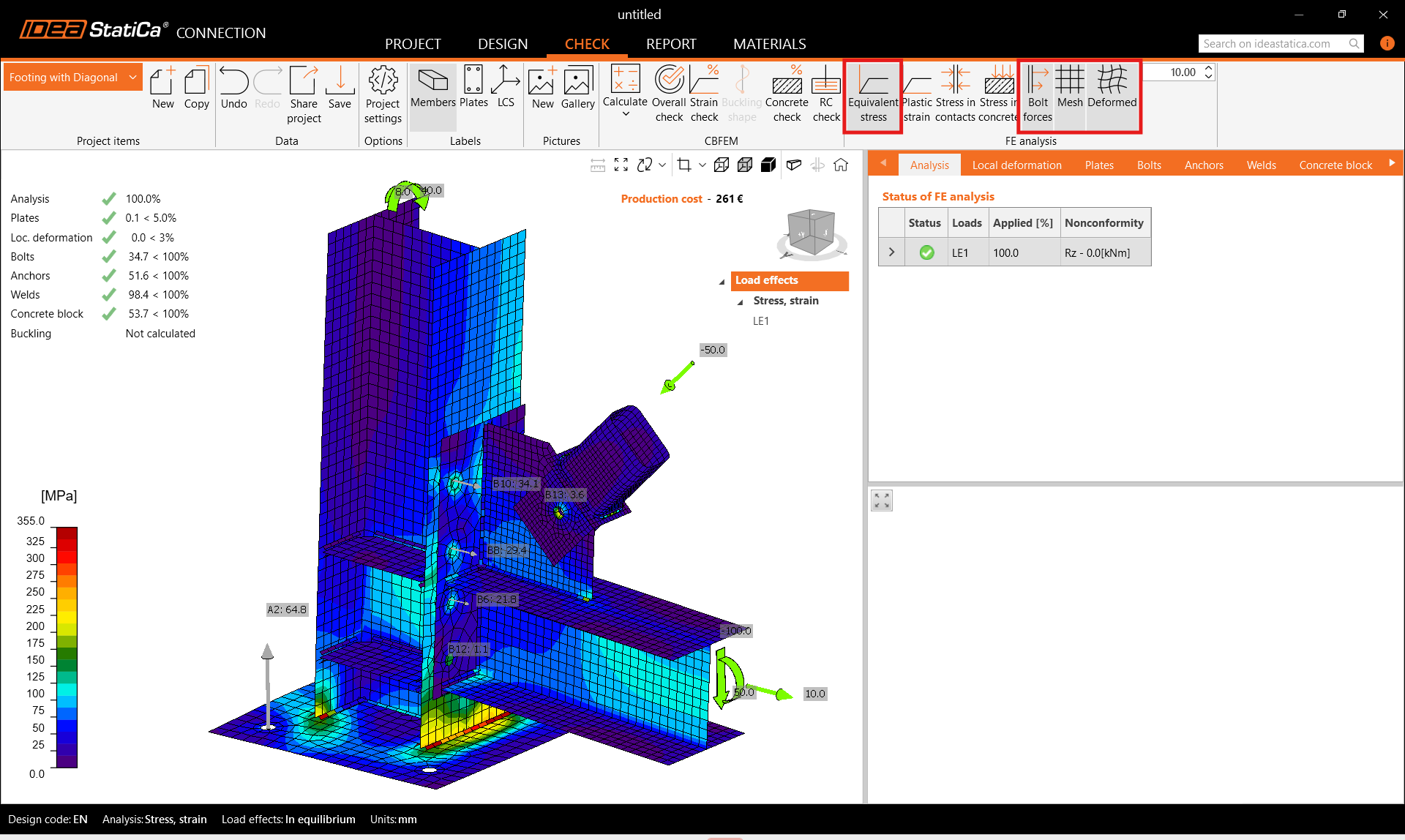
Accedere alla sezione Verifica nella barra multifunzione superiore, e attivare Tensione equivalente, Forze nei bulloni, Rete e la forma Deformata della struttura per ottenere un quadro completo del comportamento del giunto.
Inoltre, attivare Tensione nel calcestruzzo dalla barra multifunzione superiore. Aprire la scheda Blocco di calcestruzzo per visualizzare i risultati dettagliati per questa voce.
6 Relazione
Infine, accedere alla scheda Relazione. IDEA StatiCa offre una relazione completamente personalizzabile da stampare o salvare in formato modificabile.
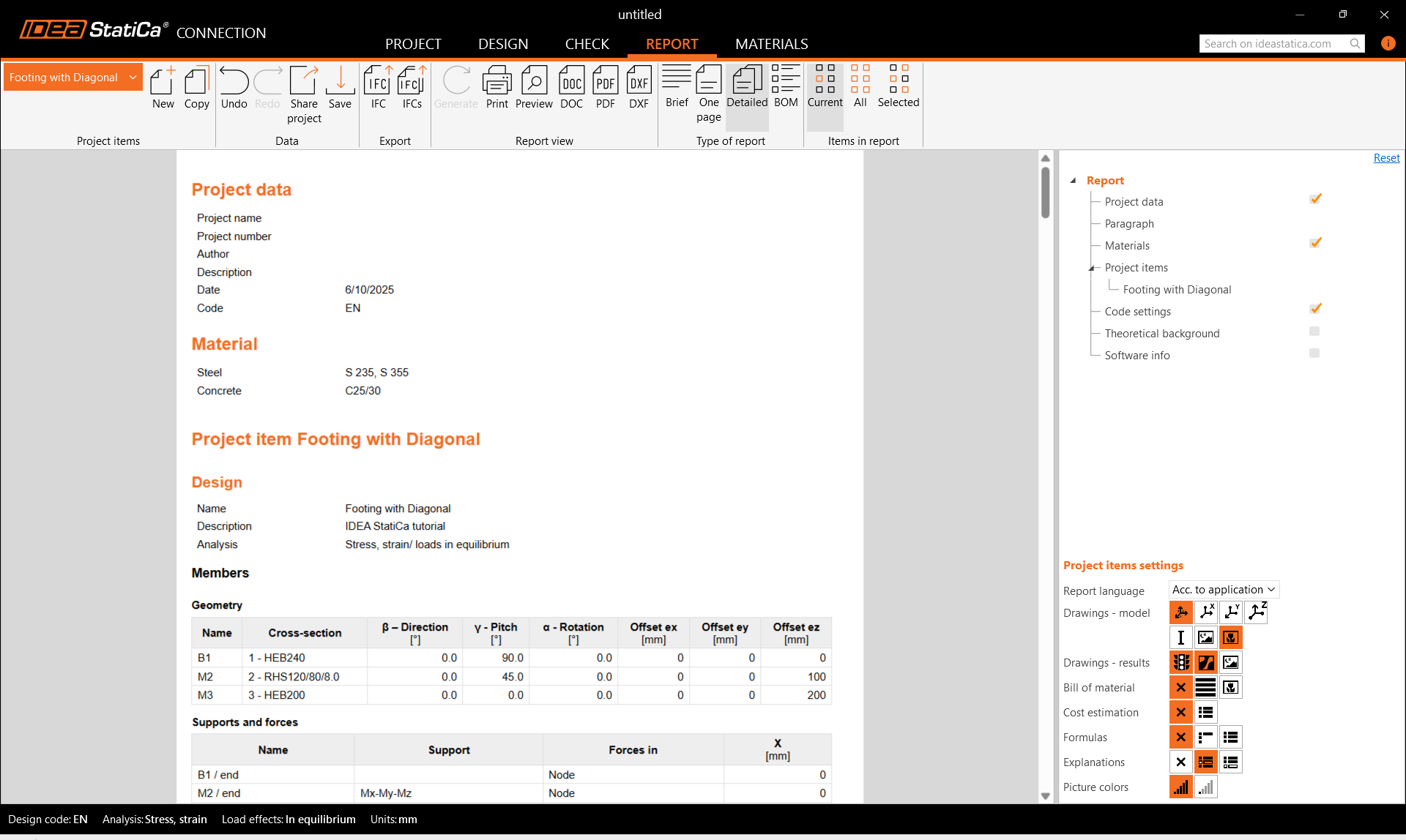
Hai progettato, ottimizzato e verificato normativamente un giunto in acciaio strutturale secondo l'Eurocodice (EN).