3D Detail – fondazioni in calcestruzzo armato (BETA)
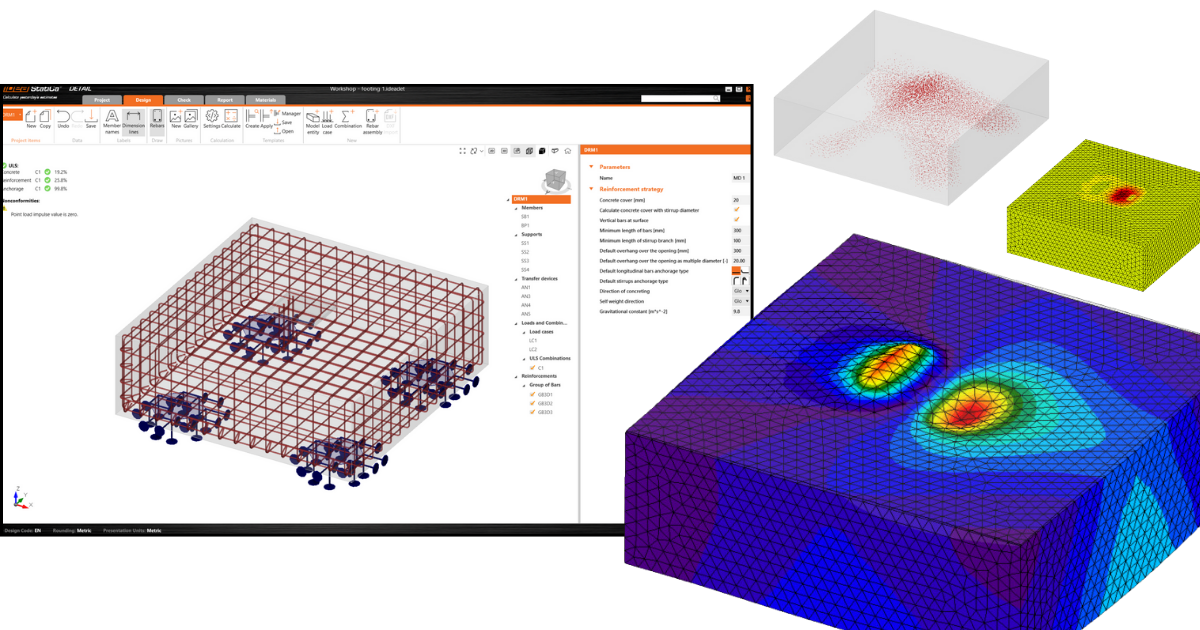
IDEA StatiCa introduce Detail (3D Beta) per la risoluzione di problemi 3D come l'ancoraggio in blocchi di calcestruzzo. La soluzione consente di eseguire la progettazione senza semplificazioni eccessive e di ottenere verifiche basate sullo Stato Limite Ultimo (SLU). Il metodo implementato in IDEA StatiCa Detail (3D Beta) si basa sul già collaudato Metodo del Campo di Tensioni Compatibile, che è stato adattato per poter risolvere problemi 3D (tensione triassiale). Anche l'elemento di base è stato modificato nella terza dimensione. Il blocco solido è l'elemento di base che rappresenta il calcestruzzo e può essere deformato in tutte e tre le direzioni. Per consentire la creazione di un modello complesso per le fondazioni, sono state implementate entità quali supporto superficiale, piastra di base, ancoraggi e altro. Tutte queste entità sono descritte, insieme alle loro funzionalità, nell'articolo seguente.
La forma del blocco solido
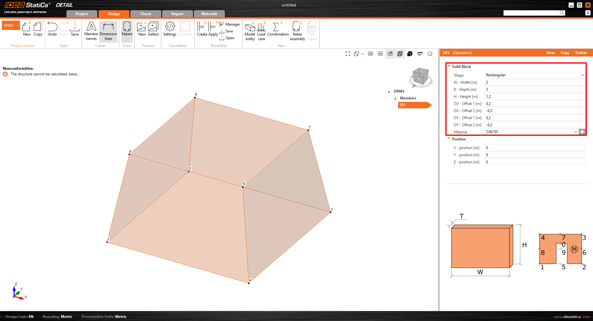
Il blocco di calcestruzzo può essere modellato grazie al tipo di elemento denominato "Blocco solido", la cui geometria può essere definita in due modi:
- Forma rettangolare – Questa opzione è adatta per definire la fondazione con base rettangolare e altezza costante. La definizione degli offset per tutti i lati del blocco consente anche la modellazione di fondazioni inclinate.
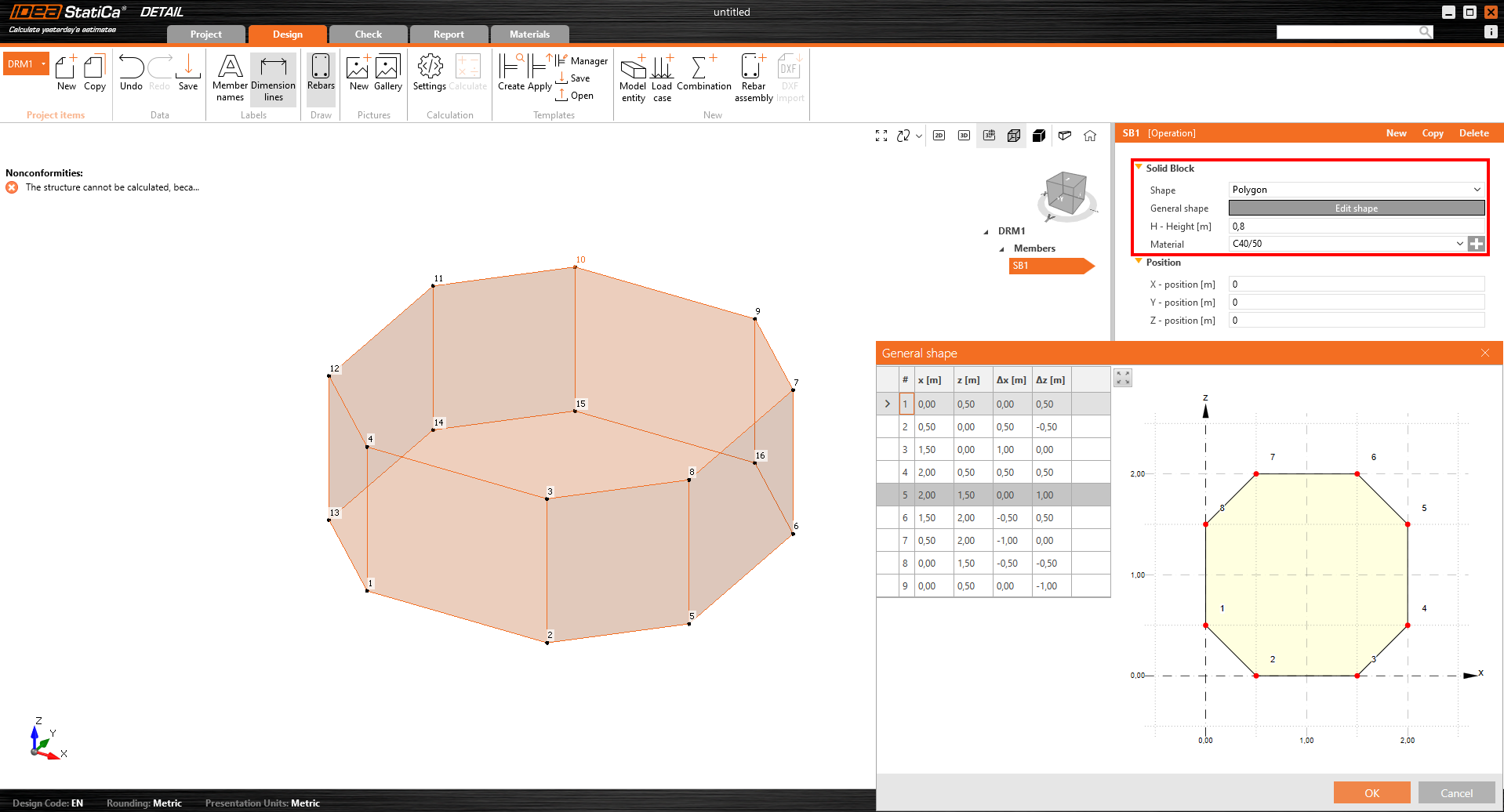
- Base poligonale con altezza definita – La seconda opzione per la definizione della forma della fondazione è la definizione della forma della base come poligono generico. Tuttavia, non è possibile creare fondazioni inclinate come descritto nell'opzione precedente.
Supporti superficiali
Il supporto superficiale è l'unico tipo di supporto che può essere definito per il modello solido. Sono disponibili due opzioni per la definizione della forma – può essere definito per l'intera superficie o come area generica il cui contorno è determinato da una polilinea.
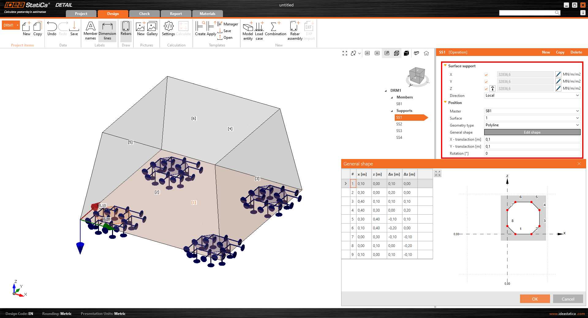
Il vantaggio del supporto superficiale è la possibilità di definire la rigidezza e impostare un comportamento non lineare che simula il contatto con il terreno. I supporti definiti da forma generica (polilinea) possono essere utilizzati per simulare i pali.
Dispositivi di trasferimento del carico
In particolare per l'ancoraggio, sono state sviluppate due entità per il trasferimento dei carichi:
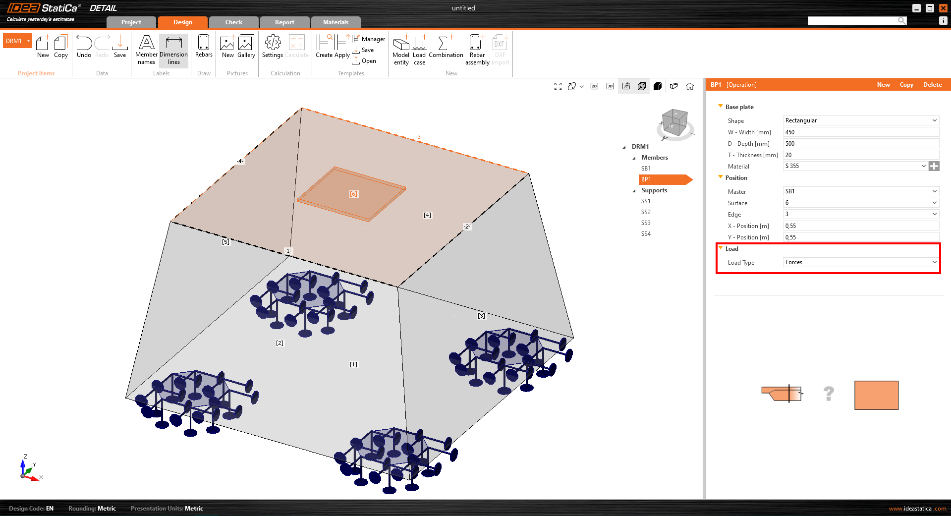
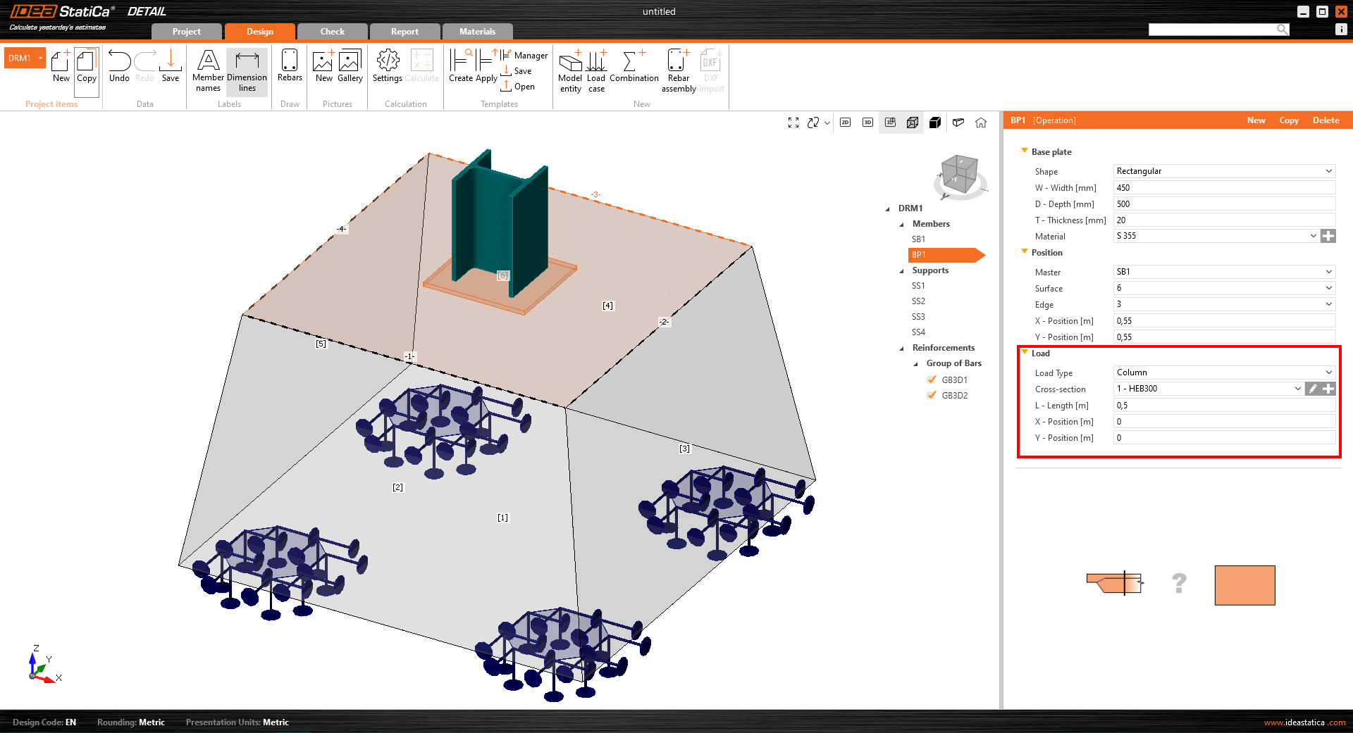
- Piastra di base – La forma della piastra di base può essere definita come rettangolo o come polilinea generica. La piastra di base può essere modellata con la parte del pilastro (opzione "Trasferimento del carico – Pilastro") o senza il pilastro (opzione "Trasferimento del carico – Forze"). Quando si seleziona l'opzione "Trasferimento del carico – Forze", il carico definito viene applicato direttamente alla piastra di base. Quando il pilastro in acciaio è definito (tramite la sua sezione trasversale e lunghezza), il carico viene applicato alla sommità del pilastro e la sua rigidezza contribuisce a distribuire correttamente le tensioni sulla piastra di base.
- Ancorante singolo – Un ancorante singolo è un elemento 1D che consente il trasferimento del carico assiale. L'ancorante può essere automaticamente collegato alla piastra di base oppure può essere caricato direttamente da un carico concentrato*.
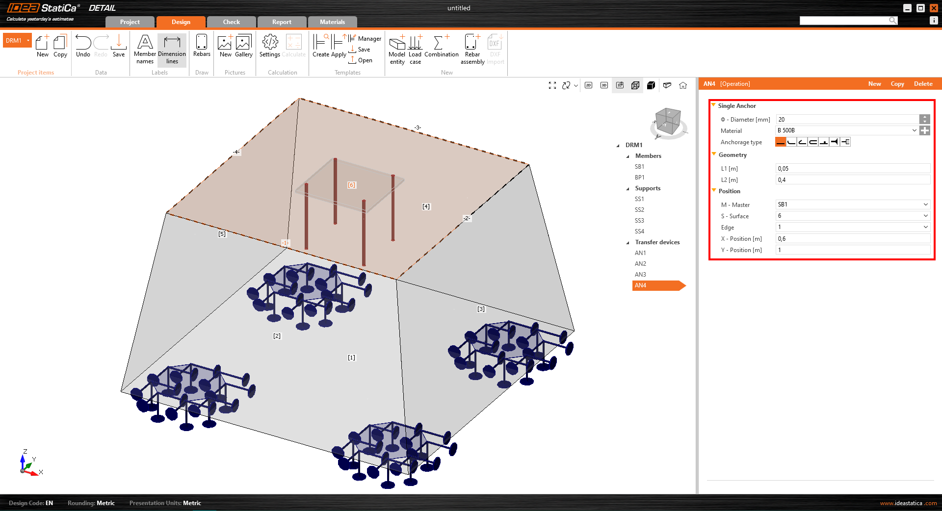
*Esistono alcune limitazioni per gli ancoraggi nella versione BETA.
L'ancorante trasmette solo compressione e trazione. Il taglio, se importato da Connection, viene trasferito per attrito tra il blocco di calcestruzzo e la piastra di base. All'ancorante può essere applicata solo la forza assiale.
Nell'applicazione Detail sono disponibili due diversi tipi di ancoraggi:
- Gettato in opera – Armatura
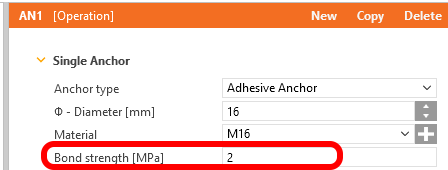
- Ancorante chimico
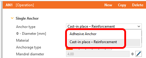
Per l'ancorante chimico, nell'analisi entra in gioco un ulteriore parametro – la resistenza di aderenza. Questo valore è impostato per default a 2 MPa e deve essere adeguato dall'utente in base alle informazioni della scheda tecnica del produttore dell'ancorante.
Carichi
L'aggiunta di un gruppo di forze e di un carico superficiale è essenziale per la facilità d'uso. In totale, sono supportati tre tipi di carico:
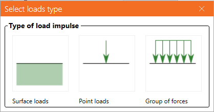
- Carico superficiale – Il carico superficiale può essere applicato a qualsiasi superficie in calcestruzzo. Può essere applicato all'intera superficie o solo su una sua parte su una determinata area, il cui contorno è definito dalla polilinea.
- Carico concentrato
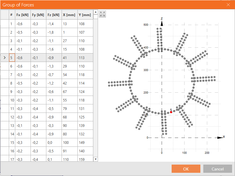
- Gruppo di forze – Un gruppo di forze è un'entità che definisce più carichi concentrati che agiscono come un gruppo. Può essere applicato sulla piastra di base o sulla superficie in calcestruzzo. Questo tipo di carico può essere utilizzato per simulare le forze nelle saldature che trasferiscono le tensioni dal pilastro alla piastra di base.
Armatura
È stato sviluppato un nuovo tipo di armatura che consente di armare adeguatamente una fondazione. Un Gruppo di barre offre diverse opzioni per la definizione delle barre di armatura:
- Per due punti
- Sul bordo della superficie – Sul bordo della superficie – viene creato uno strato di armatura parallelo alla superficie selezionata. L'utente definisce il numero di barre in uno strato e il numero di strati paralleli alla superficie selezionata.
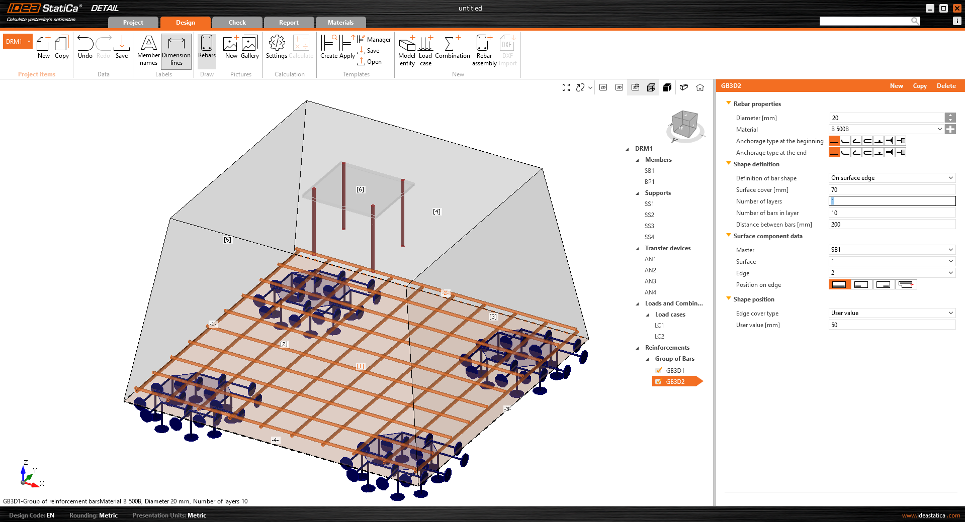
- Su un bordo o più bordi della superficie – Su un bordo o più bordi della superficie consente la modellazione di strati di armatura con forma complessa (curva piana relativa a qualsiasi superficie in calcestruzzo). Lo strato è quindi determinato da una sola barra. Tuttavia, è possibile definire più strati paralleli. Il copriferro può essere definito indipendentemente per ciascun bordo. Questa è la migliore opzione per modellare le staffe.
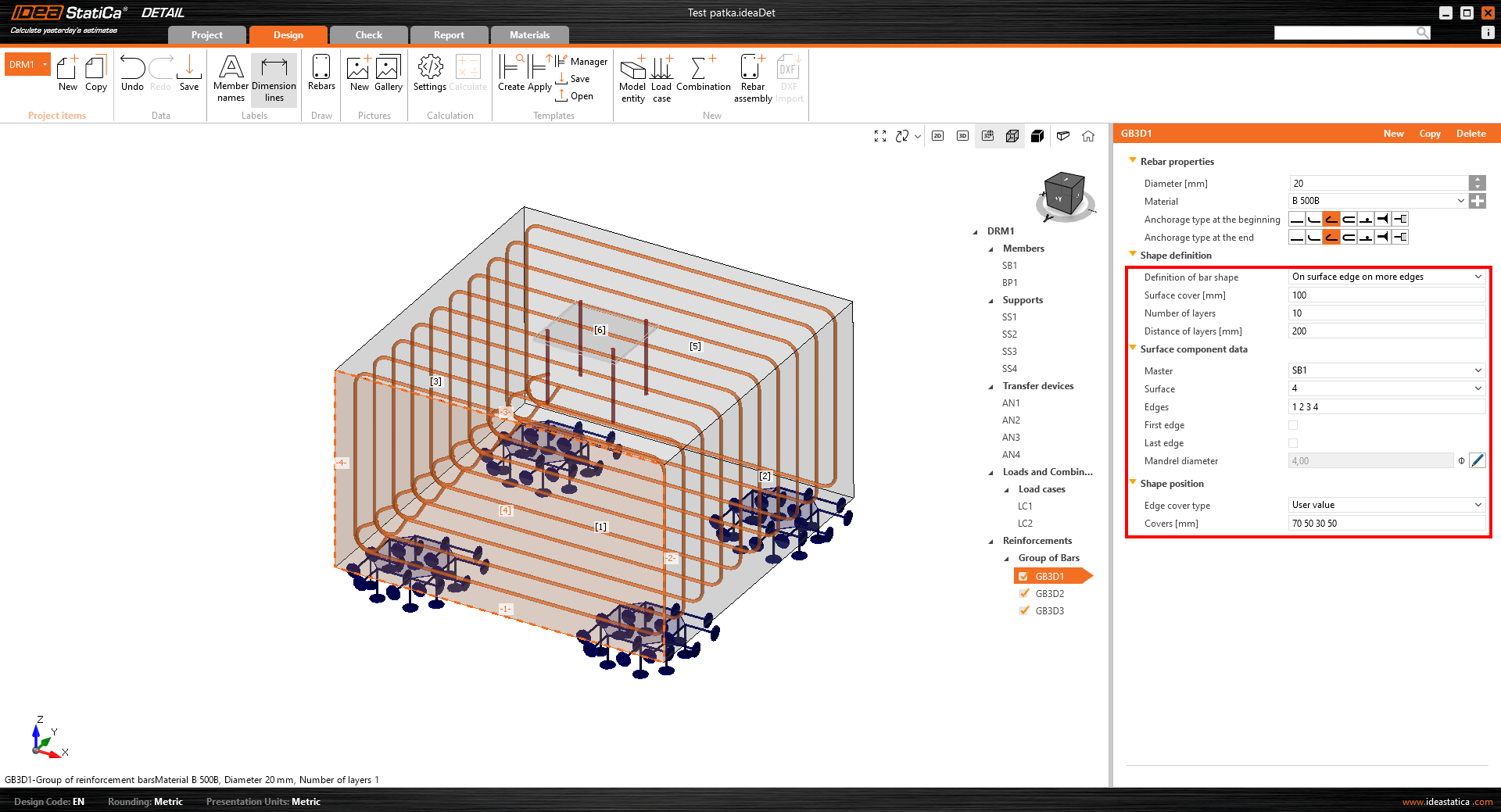
- Su polilinea
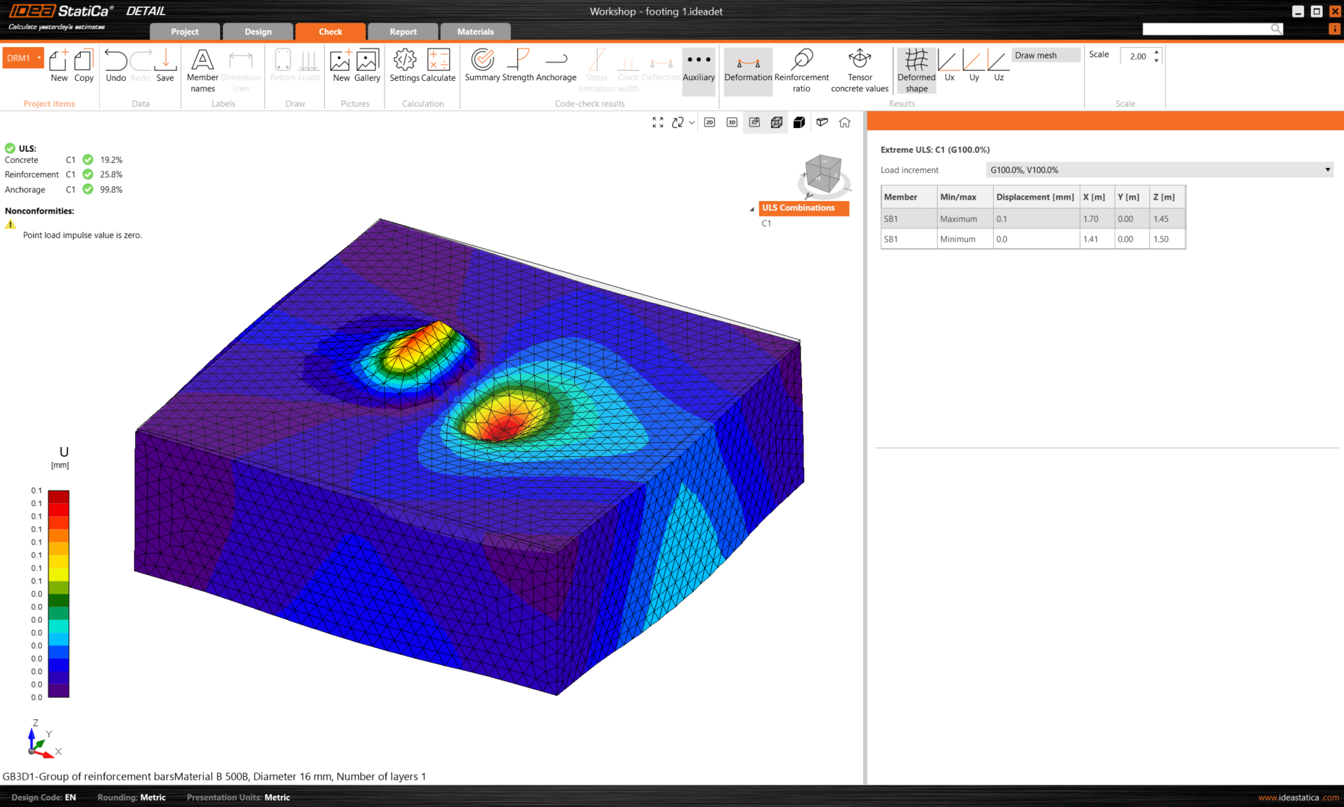
Risultati
Nella scheda dei risultati, si trovano tre valutazioni fondamentali in conformità con lo SLU (Stato Limite Ultimo).
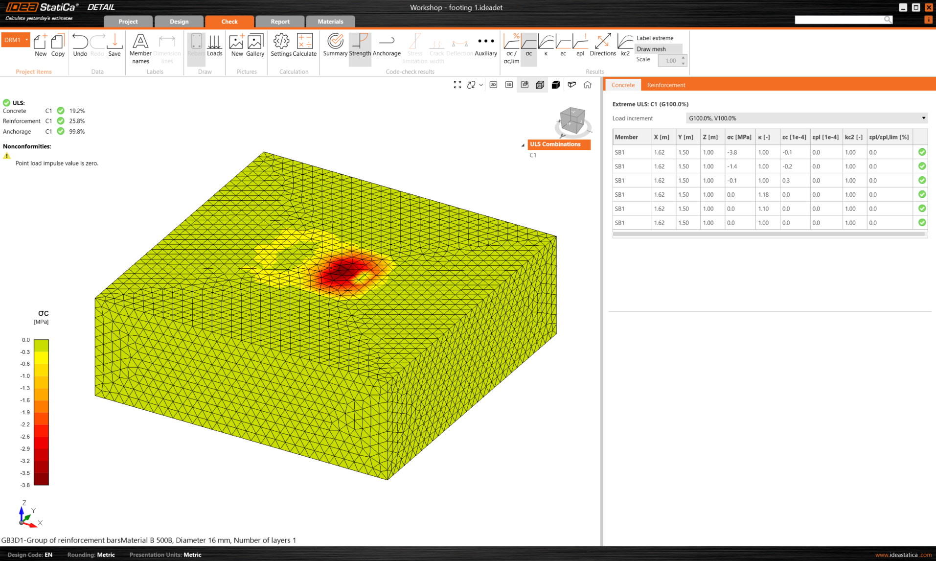
I risultati delle tensioni e delle deformazioni nel calcestruzzo e nell'armatura sono presentati nella sezione "Resistenza". Le tensioni di aderenza e i valori correlati si trovano nella verifica "Ancoraggio". Un valore molto importante della deformazione non lineare è presentato nella verifica "Ausiliaria".
Limitazioni della versione 3D BETA
L'obiettivo della versione BETA rilasciata è quello di offrire agli utenti la possibilità di familiarizzare con essa, testare la soluzione e fornirci un feedback. Per chiarire le aspettative dalla versione BETA di 3D Detail, nella versione attuale sono presenti alcune limitazioni:
- Non è previsto il trasferimento di forza di taglio negli ancoraggi – il taglio viene trasferito solo per attrito tra la piastra di base e la superficie del blocco di calcestruzzo.
- I risultati dell'analisi e le verifiche normative sono limitati allo SLU (stato limite ultimo)
- Il tempo di calcolo di un singolo modello di un blocco di calcestruzzo e di una piastra di base con una griglia di ancoraggi può richiedere fino a 10 minuti
- Le Sezioni per la visualizzazione dei risultati saranno disponibili nella BETA 2
- Il peso proprio degli elementi del modello non viene preso in considerazione
- Nel modello può essere utilizzato solo un blocco solido di calcestruzzo
La soluzione 3D per Detail è in fase di sviluppo intensivo e di processo di verifica. Con la versione 24.0 viene rilasciata la prima BETA di 3D Detail; la BETA 2 è prevista per luglio 2024 con miglioramenti nell'interpretazione dei risultati, la riduzione dell'elenco delle limitazioni attuali e l'introduzione di funzionalità aggiuntive. La BETA di 3D Detail sarà trasferita alla versione ALPHA al termine di un approfondito processo di verifica e rilasciata con la versione 24.1.
Descrizione del modello e verifiche
Per saperne di più sul modello analitico 3D Detail, leggere l'articolo sul background teorico:
Inoltre, le prime verifiche del modello e dei risultati di 3D Detail sono state pubblicate nei seguenti articoli:
- Verifica 3D Detail: Prova di flessione semplice
- Verifica 3D Detail: Prova di ancoraggio
- Verifica 3D Detail: Prove a taglio in travi con bassa quantità di staffe
È inoltre possibile fare riferimento agli articoli sul background teorico di Detail, validi sia per i modelli 2D che 3D, riguardanti gli elementi finiti e l'interpretazione dei risultati SLU:
Offriamo un accesso anticipato a questa versione Beta per consentirvi di provarla direttamente, mentre continuiamo a sottoporla al nostro rigoroso processo di verifica. Questa è accessibile agli utenti attuali con l'ultima versione e una manutenzione valida. Se si soddisfano i prerequisiti, è possibile richiedere l'accesso gratuito facendo clic sull'icona Beta Detail nella barra multifunzione dell'applicazione Connection, che rimanda a questa pagina di destinazione, dove è possibile compilare il modulo e richiedere di aderire al programma Beta e ottenere l'accesso gratuito a 3D Detail.
Nota: Le verifiche normative in 3D Detail sono attualmente disponibili solo per l'Eurocodice (EN).