Elementi di traliccio e IDEA StatiCa
Contesto e considerazioni preliminari
Benvenuti al mio sesto post del blog! Come è diventata tradizione, mi piace portare un tocco personale. Quanti di noi ricordano quando hanno analizzato la loro prima travatura reticolare? Per me avevo 18 anni ed ero al secondo anno del sesto anno di studi per gli A Level. La materia era Disegno Tecnico e il metodo era la Notazione di Bow.
Quanti ingegneri (più anziani) se lo ricordano? Avanzando di qualche anno, una travatura reticolare è stato il primo sistema strutturale che ho realizzato all'università – ammettendo, con altri tre membri del team. È stata tagliata, forata, imbullonata e testata fino alla rottura – il che non ha richiesto molto tempo, mi affretto ad aggiungere!
Le travature reticolari ovviamente si presentano in molte forme e dimensioni e sono realizzate con materiali così diversi che è difficile contarli – ricordate le strutture con cannucce da bibita? Il denominatore comune però è sempre stato il giunto – non solo come dovrebbe essere trattato, ma anche come dovrebbe essere progettato. Per le loro dimensioni, offrono capacità portanti eccezionali, il che è uno dei motivi per cui sono una soluzione 'di riferimento' per situazioni difficili!
Ho sempre avuto un amore per il legno – molto probabilmente perché sono un appassionato di edifici storici e di costruzione. Il legno è stato il primo materiale strutturale utilizzato per formare travature reticolari. Le travature reticolari in legno risalgono al 2500 a.C. Gli antichi Greci le utilizzavano nei loro tetti e hanno avuto un ruolo importante nell'architettura medievale.
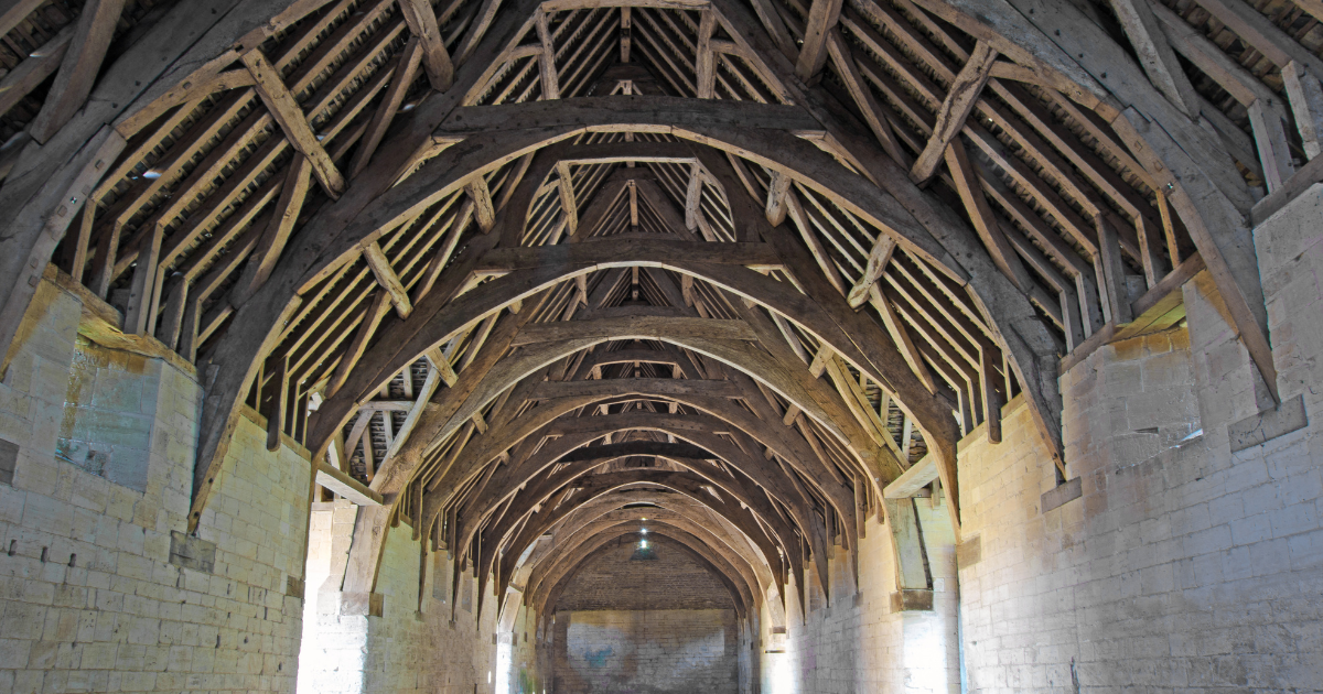
Molti dei vecchi granai delle decime furono costruiti utilizzando questi metodi. I giunti erano formati all'interno degli elementi in legno utilizzando tradizionali mortase e tenoni con cavicchi in legno o simili. Gli strumenti a cui i maestri artigiani del passato avevano accesso erano alquanto limitati, il che ha dato origine a opere d'arte tridimensionali piuttosto che a semplici strutture per tenere fuori vento e pioggia.
Le travature reticolari in legno sono sempre state utilizzate nell'edilizia residenziale, dalle dimore medievali alle abitazioni moderne. Ciò che è cambiato drasticamente sono i metodi e le forme utilizzate. Le moderne capriate in legno di oggi, con i loro elementi snelli e le piastre di collegamento ingegnerizzate, sono ben lontane dall'immagine sopra.
Quando si esamina l'evoluzione delle travature reticolari in acciaio, bisogna prima guardare al ferro, sia ghisa che ferro battuto, e al suo ruolo. Il settore in gran parte responsabile di questo sviluppo è quello dei trasporti – si pensi alle ferrovie (in tutto il mondo).
Ci sono molti ottimi esempi sparsi per il globo:
Travatura reticolare lenticolare di Brunel – Royal Albert Bridge - Ferro

Il Ponte Ferroviario del Firth of Forth - Acciaio

Con i ponti che guidano la strada nel design intelligente ed elegante, chi avrebbe fatto un passo avanti dal punto di vista edilizio? Nel 1889, la 'Dama di Ferro' fu costruita a Parigi (nota anche come Torre Eiffel). Sebbene costruita in ferro battuto, è forse uno degli edifici più iconici al mondo che presenta travature reticolari e l'azione reticolare.

Naturalmente, le strutture moderne si affidano sempre di più alle travature reticolari per superare situazioni particolari o luci libere. Esistono diversi tipi di travature reticolari, alcuni con nomi speciali:
- travatura ad arco
- travatura a ventaglio
- travatura fink
- travatura gambrel
- travatura howe
- travatura con monaco
- travatura con due monaci
- trave Vierendeel (una forma di travatura reticolare)
- travatura Warren
- ecc.
L'analisi strutturale, i metodi di progetto e i materiali sono cambiati, ma la costante riguardante il difficile progetto dei giunti rimane. Essere in grado di valutare i corretti requisiti di carico su una travatura reticolare (e su qualsiasi struttura) è fondamentale. Molte travature reticolari hanno le loro radici nella geometria, quindi è importante che la geometria sia riconosciuta anche come un fattore importante, a volte architettonico.
E IDEA StatiCa?
Gli elementi stessi (in una travatura reticolare in acciaio) sono spesso snelli e sono quindi soggetti a effetti aggiuntivi che potrebbero portare un progettista a considerare forme di analisi più avanzate. Disporre di una soluzione software in grado di combinare tutti questi requisiti con una funzionalità facile da usare è assolutamente essenziale nel mondo dell'ingegneria strutturale odierna.
Per fortuna, esiste IDEA StatiCa. IDEA StatiCa Connection può progettare i complicati collegamenti di travature reticolari di oggi in modo sicuro ed efficiente – sono disponibili anche collegamenti avanzati in legno (con piastre). Può utilizzare il modello analitico di diverse soluzioni FEA tramite un'applicazione chiamata IDEA StatiCa Checkbot. Checkbot fornisce il collegamento tra FEA e IDEA StatiCa Connection. Se il progettista è preoccupato per gli elementi all'interno della travatura reticolare, allora abbiamo IDEA StatiCa Member. IDEA StatiCa Checkbot può essere utilizzato anche per gestire questa soluzione.
Dove si inserisce IDEA StatiCa? Si consideri un esempio semplice ma essenziale:

Queste sono probabilmente le strutture più sottovalutate nelle nostre reti stradali oggi. Sono soggette a tutti i tipi di carico usuali: permanente, variabile, vento, neve e ghiaccio. Poi ci sono anche i carichi dinamici da considerare eventualmente. Il tutto nel tentativo di progettare qualcosa che possa essere fabbricato in modo efficiente e montato rapidamente.
Questo esempio è stato semplificato poiché desideriamo concentrarci sull'interazione con la soluzione IDEA StatiCa.
Passo 1 – Analisi agli Elementi Finiti
La struttura è stata modellata, analizzata e progettata in un'adeguata applicazione di analisi agli elementi finiti (FEA) – in questo caso Autodesk Robot Structural Analysis. Si prega di consultare il nostro sito web per un elenco completo delle applicazioni supportate.

Il componente aggiuntivo IDEA StatiCa Checkbot è stato avviato dall'interno di Robot. L'installazione della maggior parte di questi cosiddetti componenti aggiuntivi nelle altre applicazioni supportate viene eseguita automaticamente per renderne l'uso ancora più rapido e semplice.
Passo 2 – Esportazione in Checkbot
Gli elementi e i collegamenti vengono selezionati in Robot ed esportati in Checkbot. In caso di modifiche, il modello Checkbot può anche essere sincronizzato con il FEA. I carichi esterni inseriti nel modello FEA vengono utilizzati per l'analisi globale e le reazioni interne – forze assiali, tagli e momenti – vengono trasferite a Checkbot. Una volta in Checkbot, sono disponibili sia per Connection che per Member.

In Checkbot è possibile anche visualizzare gli effetti del carico.
Gli elementi in IDEA StatiCa Checkbot possono anche essere uniti – quindi elementi continui composti da lunghezze più piccole possono essere uniti insieme per il progetto di un collegamento. In questo esempio, gli elementi del corrente inferiore sono stati modificati in questo modo. Al contrario, il corrente superiore non lo è stato perché nel suo collegamento non è necessario. Questo è molto utile quando si utilizzano applicazioni FEA che devono modellare elementi continui in questo modo.
Passo 3 – Progetto e verifica dei collegamenti
I collegamenti possono essere progettati e verificati con IDEA StatiCa Connection e gli elementi possono essere verificati in IDEA StatiCa Member. Il posizionamento degli elementi è sempre stato un compromesso tra analisi e realtà. Gli elementi possono spostarsi in fase di fabbricazione per facilitarne la saldatura – questo può spesso causare problemi nel modello analitico. In IDEA StatiCa, possiamo modificare le eccentricità per tenere conto di questa discrepanza.

È all'interno della soluzione Connection che è necessario ricordare di far corrispondere il modello di analisi quando si esamina il Tipo di Modello. Se si intende utilizzare collegamenti a bullone singolo in una tradizionale piastra di nodo, è necessario ricordare di modificare il Tipo di Modello di conseguenza – in N,Vy,Vx – uno che non consente momenti. Tuttavia, se il collegamento (come in questo esempio) può sopportare un momento, questo passaggio può essere evitato.
Lavorare con le effettive combinazioni di carico di progetto è indispensabile per ottenere un modello di collegamento sicuro ed efficiente e una verifica normativa. Utilizzando quattro semplici operazioni per creare un giunto completamente saldato, possiamo vedere che tutti gli effetti del carico critici (le nostre combinazioni di progetto) sono stati verificati a turno e tutti risultano soddisfatti.

Passo 4 – Verifica degli elementi
Il secondo collegamento può essere progettato in modo simile prima di esaminare il controvento in IDEA StatiCa Member.

Ciò che questo mostra, tuttavia, è che c'è ampio margine per approfondire ulteriori efficienze nei materiali e nei collegamenti, poiché molti elementi di travature reticolari sono sovradimensionati per compensare questa mancanza di analisi avanzata.
Considerazioni conclusive
Le travature reticolari sono una parte essenziale dell'Ingegneria Strutturale e il loro utilizzo diventerà sempre più audace. I progressi nei materiali e nei metodi di costruzione significheranno che nei prossimi anni emergeranno nuovi progetti e concetti – ne sono certo. Ciò che vedo nell'approccio di IDEA StatiCa come archivio di dati è il meglio di entrambi i mondi: possiamo lasciare che gli esperti nel campo FEA continuino a sviluppare soluzioni di livello mondiale mentre ci colleghiamo ai loro risultati e al modello per creare i modelli di collegamento e le verifiche degli elementi – un campo in cui siamo i migliori!
Spero che abbiate apprezzato questa incursione nel mondo delle travature reticolari e come noi di IDEA StatiCa possiamo aiutarvi in diversi modi. Tenete d'occhio un articolo correlato in arrivo sui controventi.
Scopri di più sulle travature reticolari e IDEA StatiCa