General cross-section editor for concrete
There are plenty of options for defining the geometry of the cross-section in the RCS application. You can use templates, table input, or import from another file.
But there can be situations when you do not find a suitable template (especially for composite sections), you have a dxf file with a cross-section created, or your cross-section is too complicated for inputting coordinates.
For such cases, there is the General cross-section editor (CSS).
In this article, we will introduce the functionalities of the tool including composing the cross-section from individual components, importing from the DXF file, and the finite element analysis of the cross-section in the editor.
Let's start with the question of how to access the editor. Simply launch the RCS application and click on the icon in Navigator -> Cross-section -> top ribbon -> CSS.
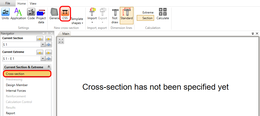
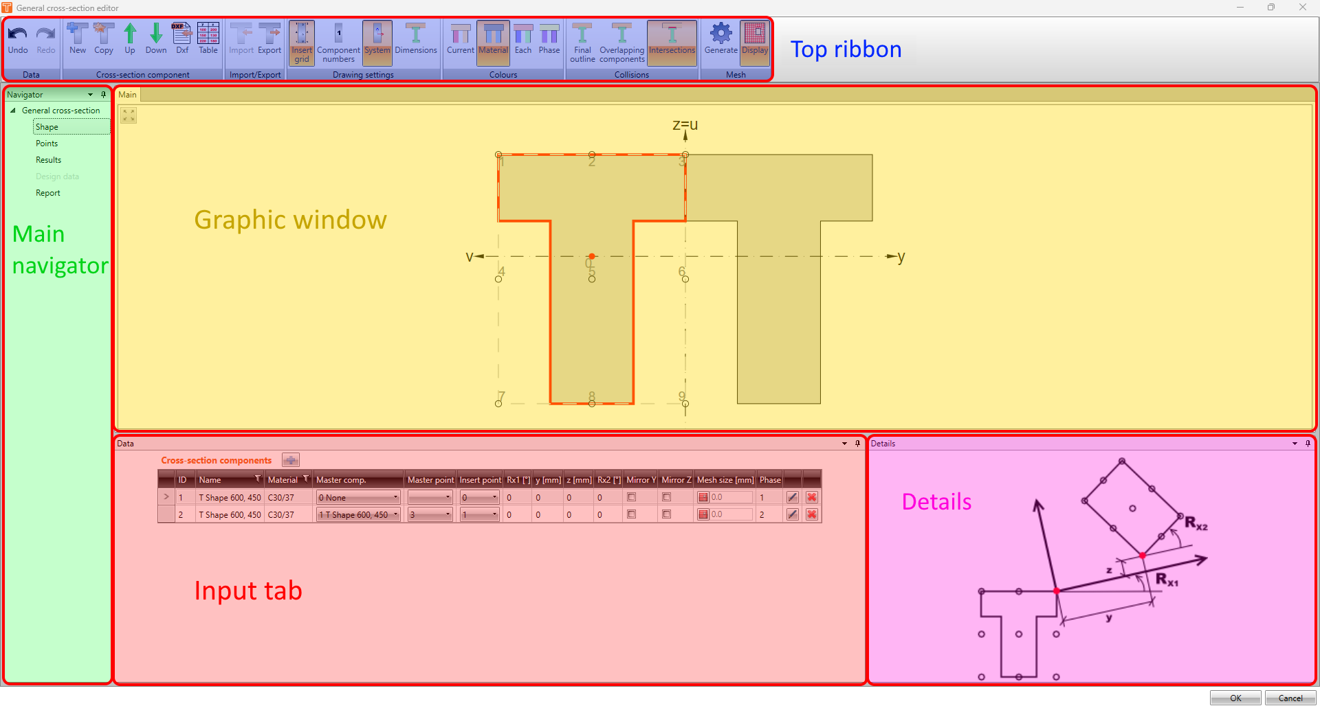
The interface of the editor is similar to the RCS application. You can see the top ribbon full of toolbars, the main Navigator on the left side, the Main graphical window, the Data window, and the Details window.
Shape
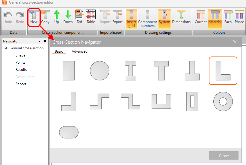
In the first section of the Navigator - Shape, you can create your section. To add a new component, use one of the options in the top ribbon in the Cross-section component toolbar. The New button allows you to add the element from the database of cross-sections.
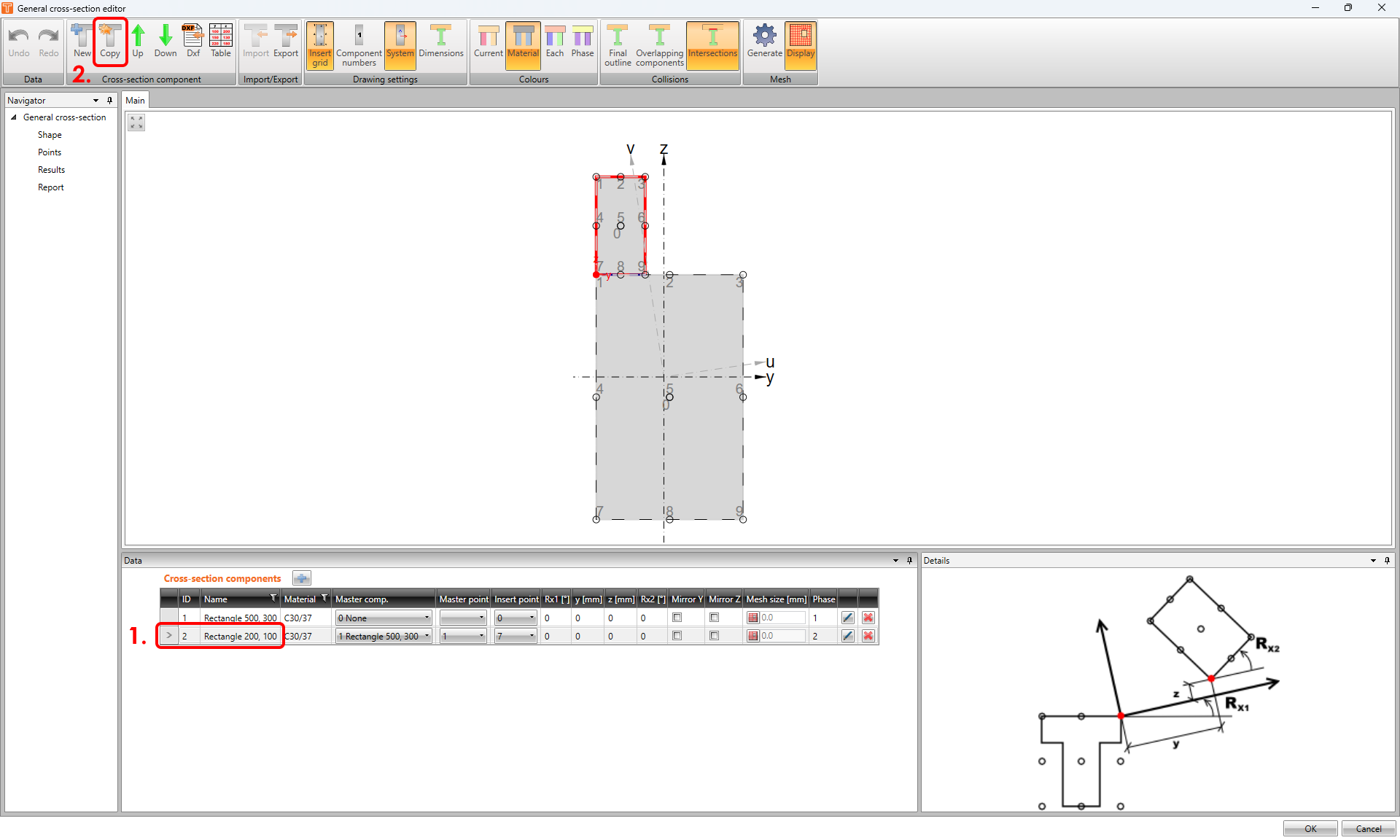
You can also copy the selected component by using the Copy button.
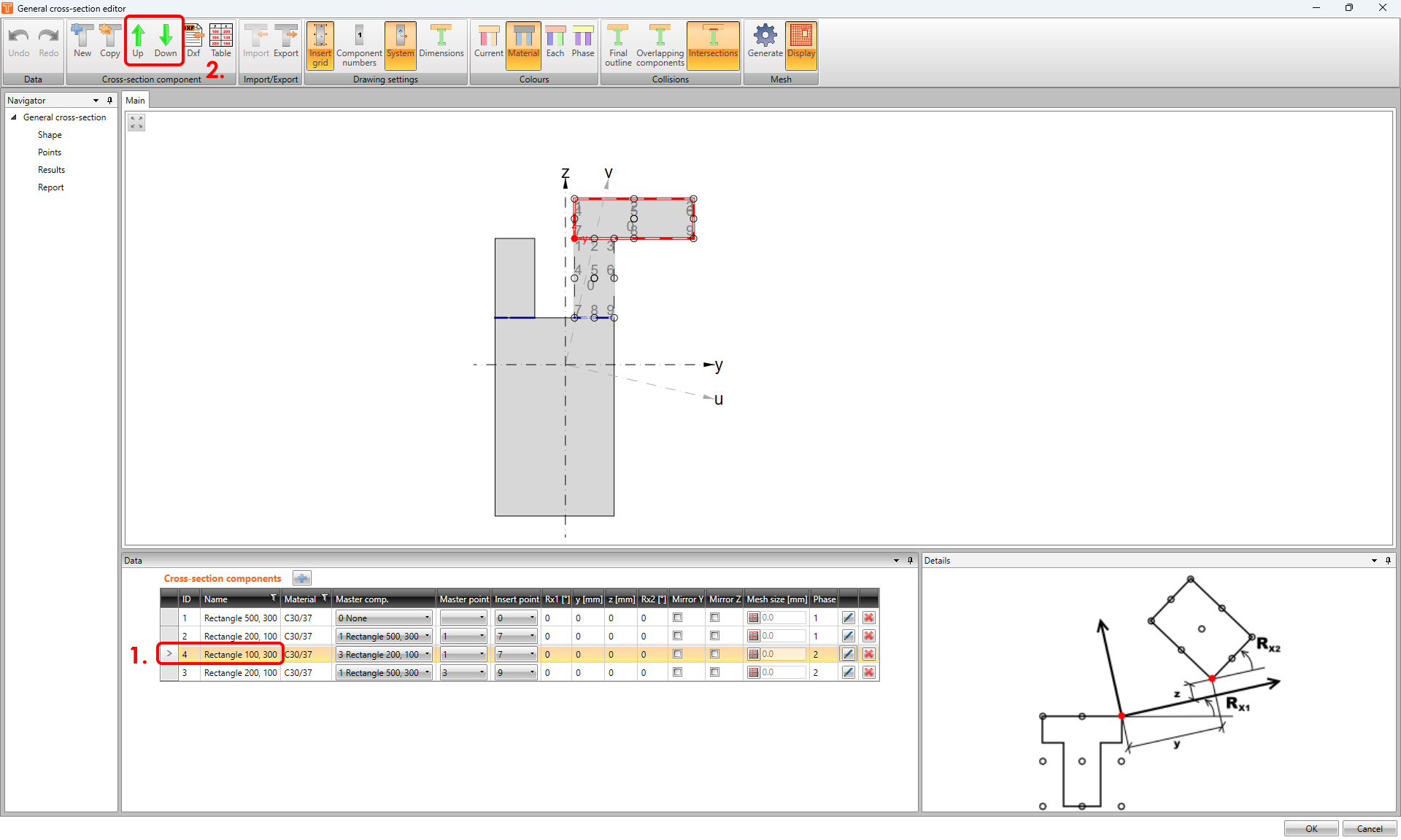
To manage the position of the components in the table use the green arrows.
Import from the DXF file
In some cases, it could be more convenient to import the cross-section's geometry from the DXF file to save time than modeling a complex shape from scratch.
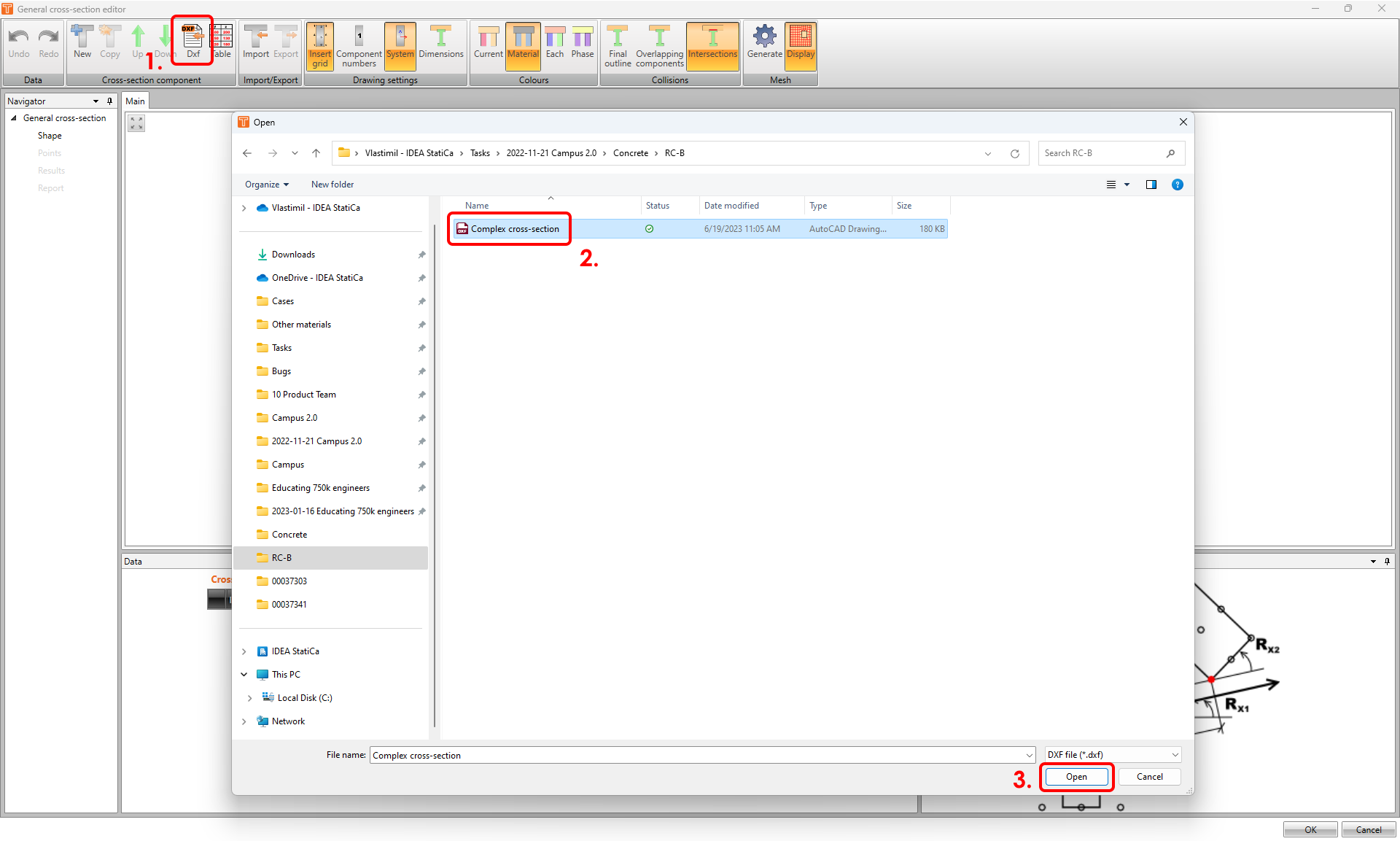
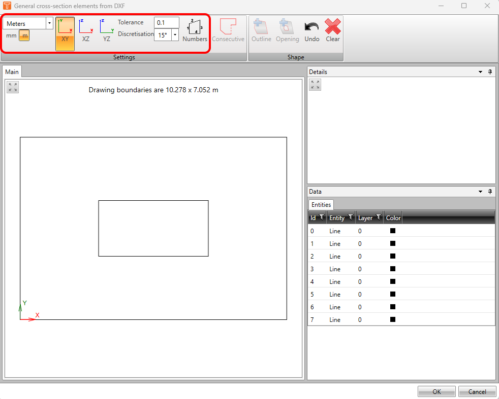
To import the section click on the DXF button in the top ribbon. Select your file and confirm.
The General cross-section elements from DXF window will appear. You can change units setting, displayed plane, tolerance, discretisation, and display (or hide) numbers of entities in the top ribbon in the Settings toolbar.
To set the outline of the cross-section select one of the lines, and click on the Consecutive button in the top ribbon in the Settings toolbar. This feature will connect all consecutive (adjacent) lines. After that, you can confirm the shape by using the Outline button.
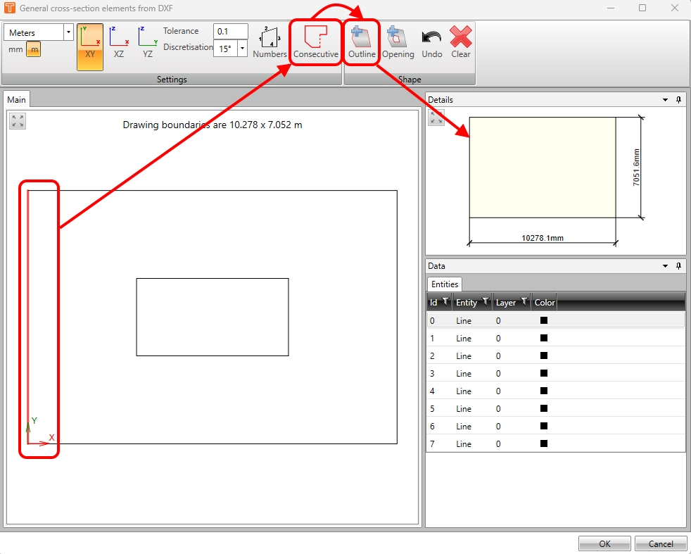
This workflow applies in case of not having the geometry in the DXF file defined by a closed polyline. If it is, you can skip the clicking Consecutive button step.
You can use the same approach to add an opening.
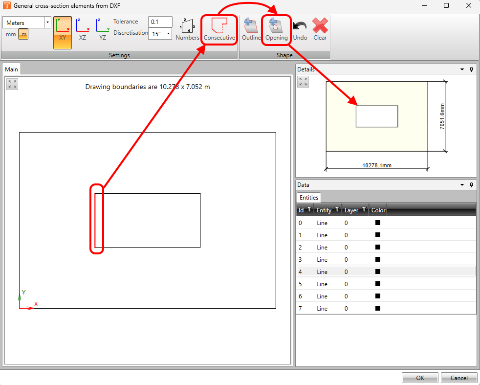
Once you are satisfied with your imported geometry, simply confirm by the OK button.
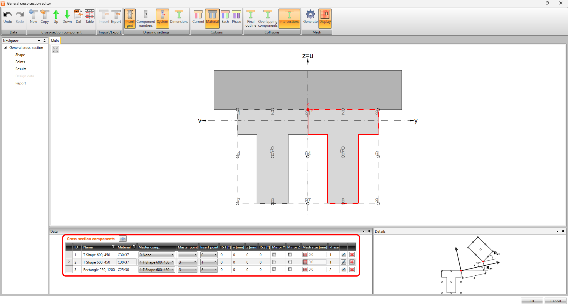
Cross-section components table
In the Data window, you can manage components of the cross-section. Each of the components can have its own name and material.
You can also set the position of the components here. The system of master and insert point is used for it.
Moreover, you can set the phase of the composite cross-section.
And last, but not least, the pencil button allows you to modify the component, and the red cross button is meant for deleting selected rows.
Displaying options
You can find three sections in the top ribbon designed for displaying tools - Drawing settings, Colours, and Collisions.
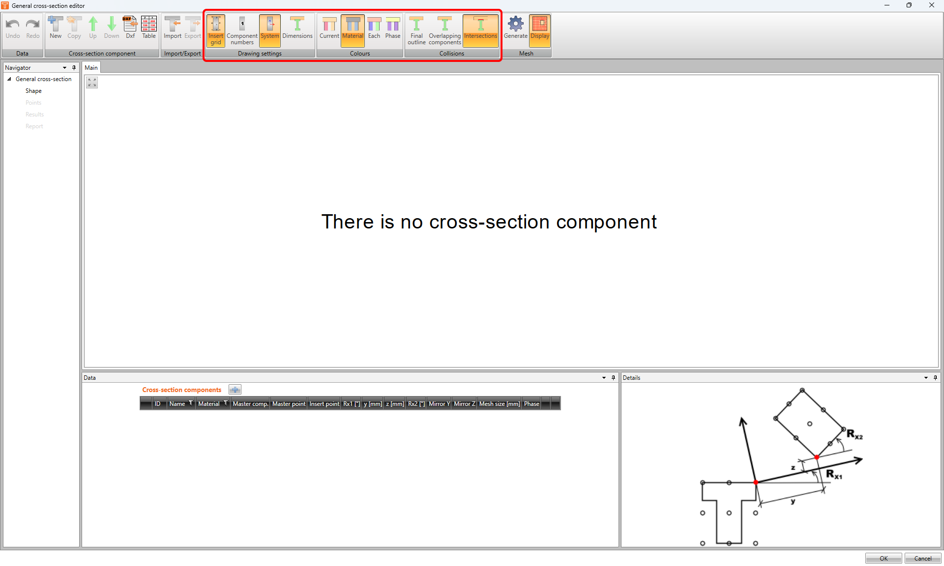
In the first one - Drawing settings, you can turn on or off the grid, numbers of the components, axis coordinate system, and dimensions.
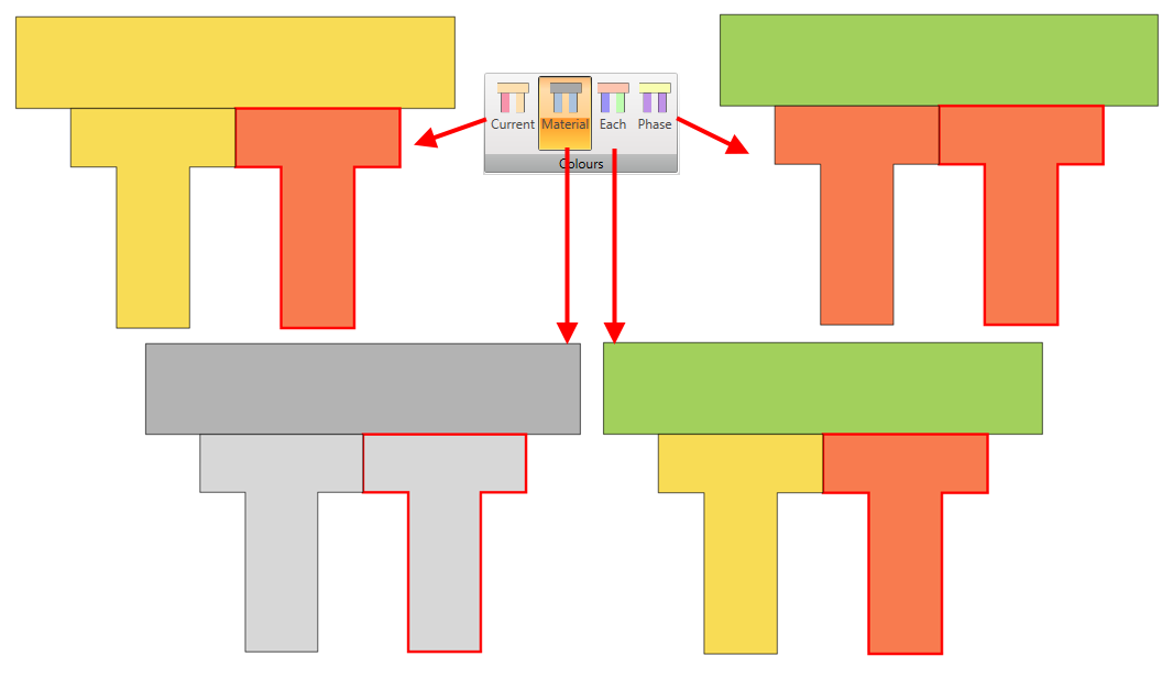
Colours section allows you to alter displaying colours for components.
And thanks to the Collisions section it's possible to see the collisions in different ways.
- Final outline crops the overlapping areas.
- Overlapping components shows collisions without highlighting them.
- Intersection highlights collisions in the scene.
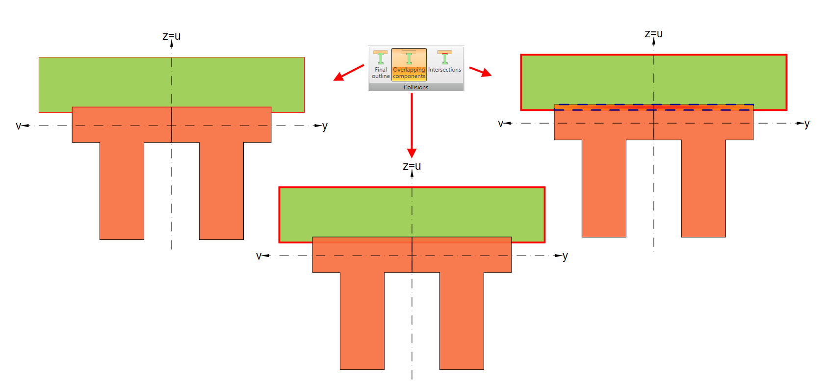
Be aware that for calculation purposes, the overlapping areas will always be cropped!
Points
As has already been mentioned, the General cross-section editor is not meant only for creating complex cross-sections. You can also calculate the section and see the corresponding results.
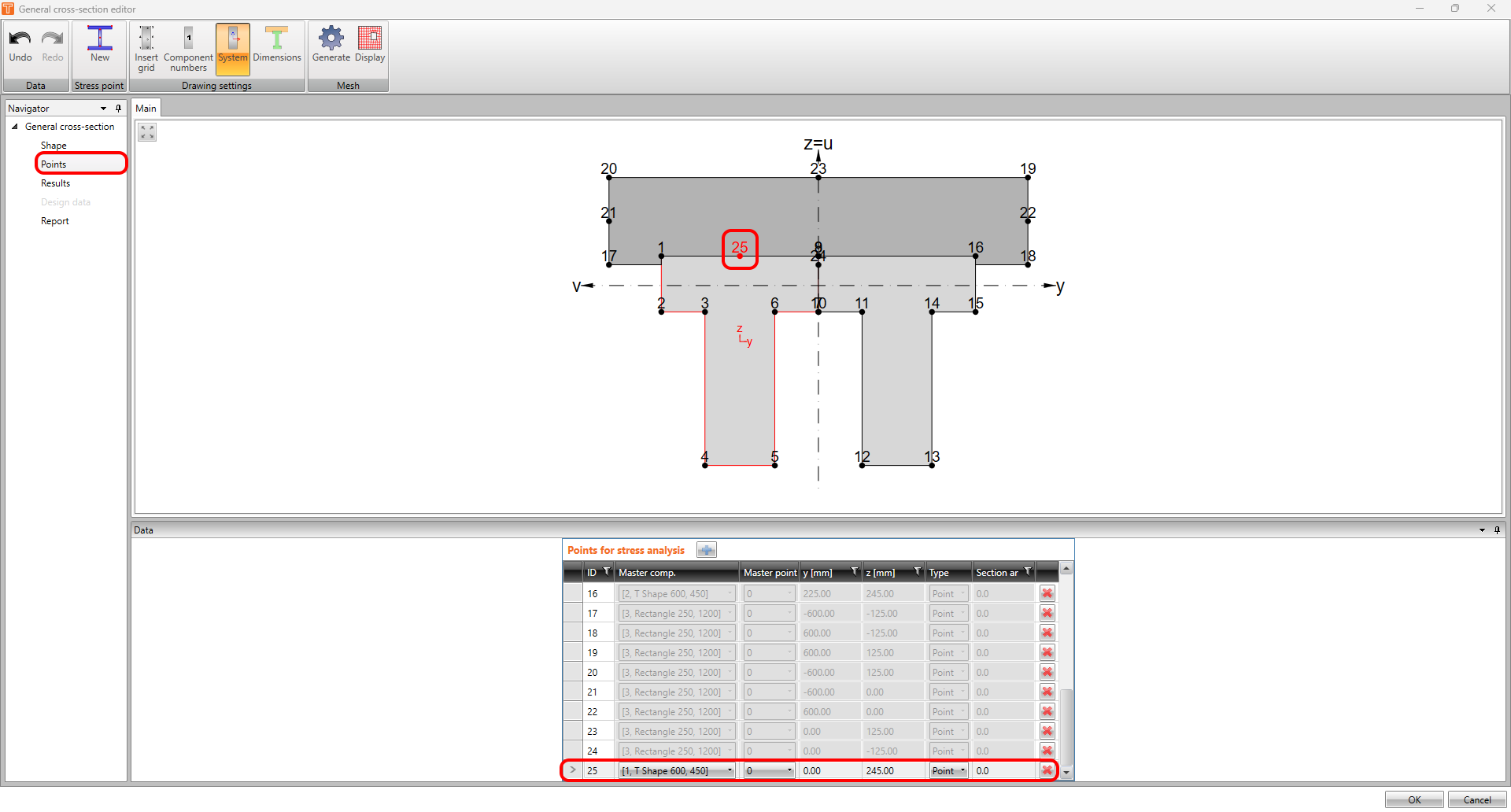
The first step is to set the calculation points. The application distinguishes two sets of points:
- Points created automatically.
- User-defined points.
The difference is shown in the following image.
The points with greyed-out rows in the table were created automatically by the software.
The highlighted last point is user-defined. The cells of the row in the table are fully editable.
Results
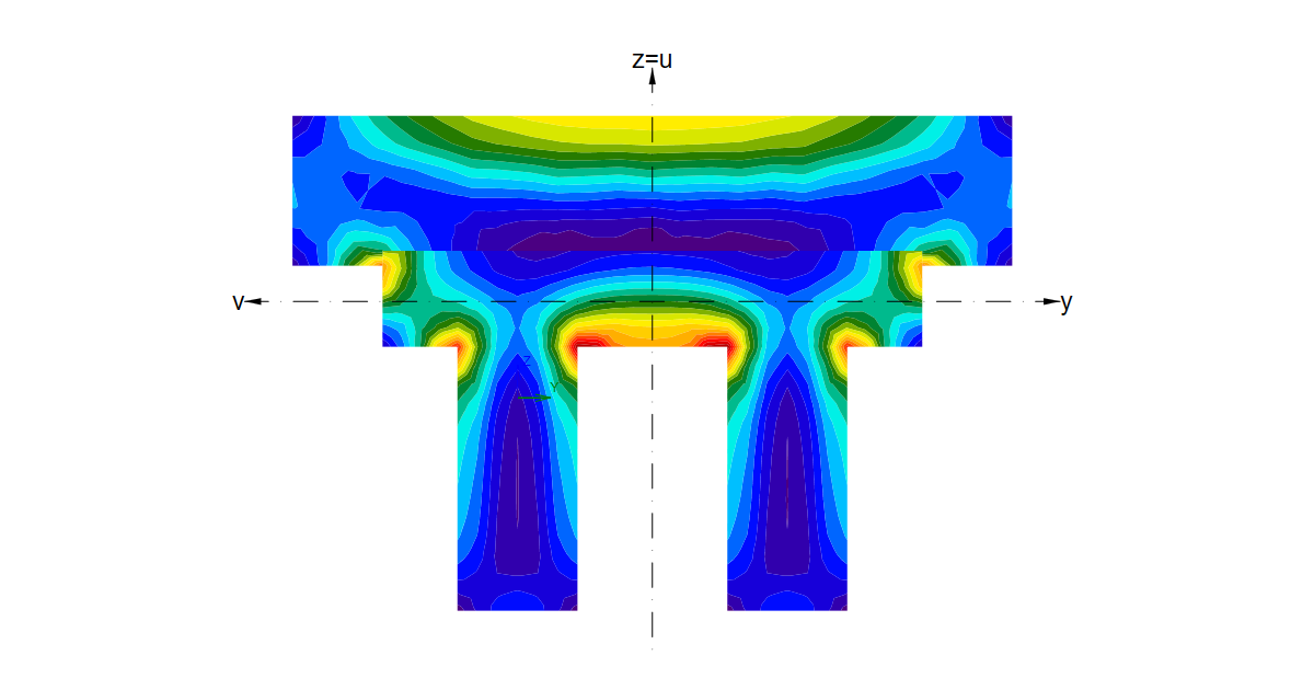
In this module, several types of finite element based calculations can be done. You can display axial or shear stresses caused by a corresponding unit internal force.
Let's show it in a practical example. In the following picture, you can see the shear stress caused by Mx = 1 kNm.
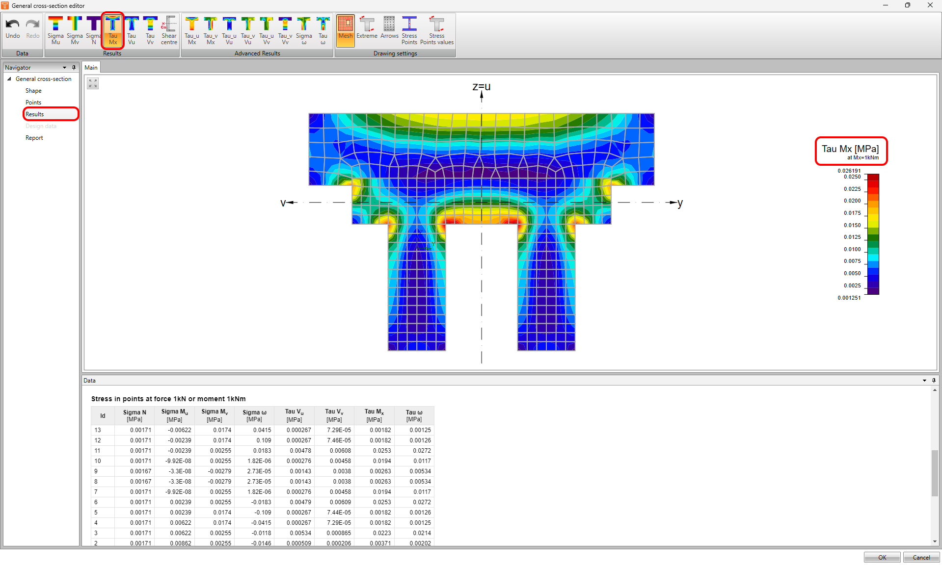
Individual results for specific points can be seen in the table in the Data window.
In the top ribbon in the Results toolbar, you can go through and display all results - Mu, Mv, N, Mx, Vu, and Vv.
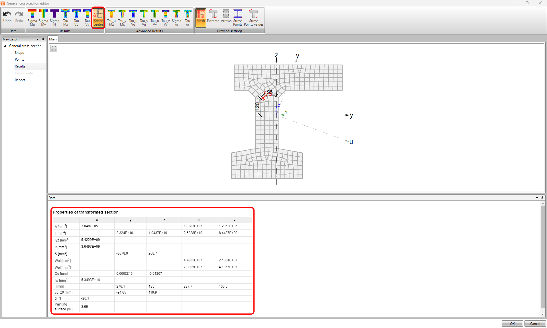
Using the Shear center button, you can display the shear center as well as other cross-section characteristics.
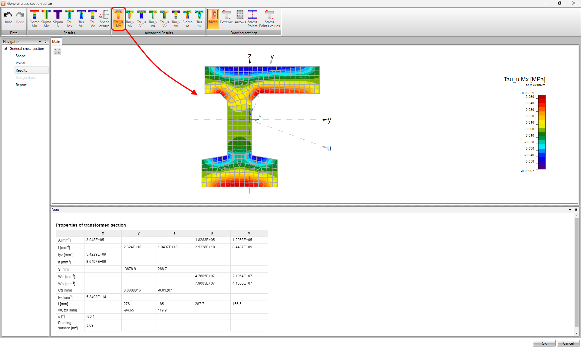
But wait, that's not all! In the top ribbon, you can even find the advanced results.
Thanks to this functionality, you can explore results such as shear stress from unit torsion, shear parallel to the first or second principal axis, direct stress due to unit bimoment, and shear stress due to unit warping moment.
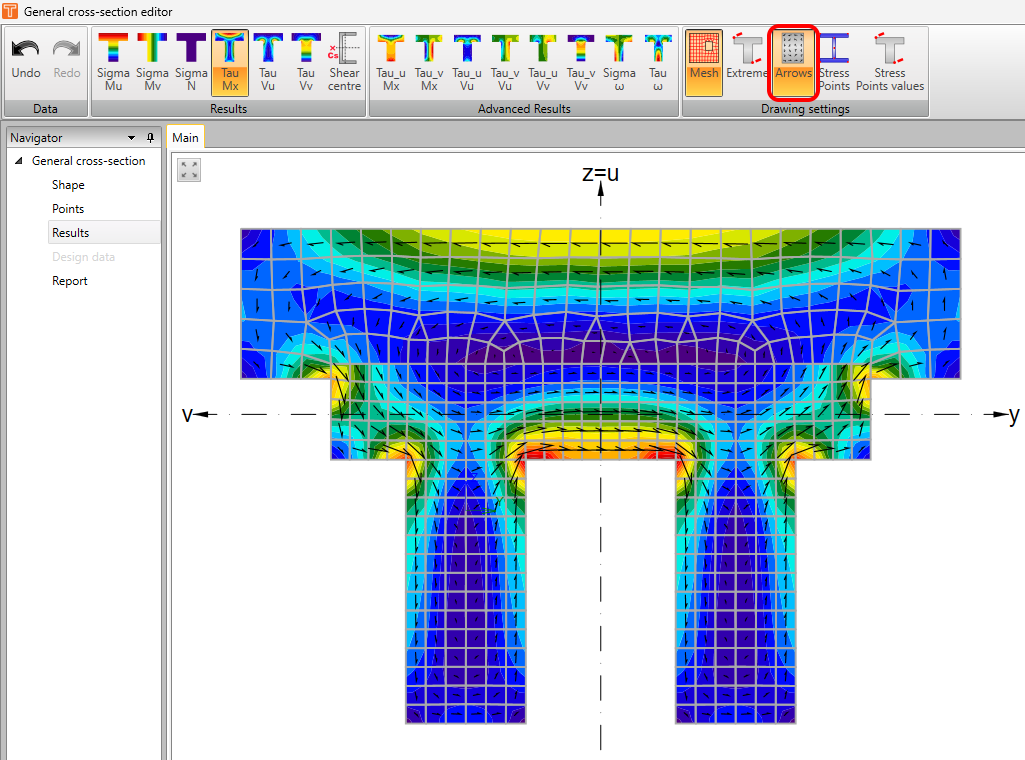
Last but not least, there is also a toolbar for Drawing settings. You can display mesh, label extremes, label stress points, and show the values in stress points. On top of that, you can display the stress flow arrows.
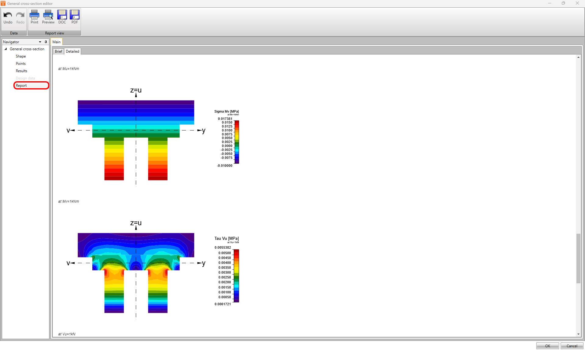
Report
Once you're finished with the cross-section, you can use the possibility of creating a report containing the above-mentioned information to make your documentation bulletproof and more eye-catching!