Csavart lemez-lemez kapcsolat tervezése (EN)
1 Új projekt
Indítsuk el az IDEA StatiCa Connection alkalmazást (töltse le a legújabb verziót).
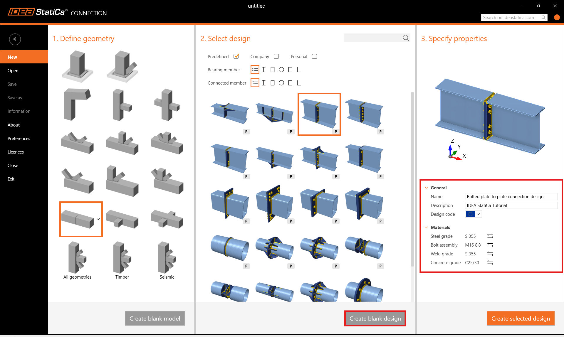
Hozzon létre egy új projektet a kívánt geometria kiválasztásával. Töltse ki a nevet, és válassza az Eurocode tervezési szabványt, az acélminőséget pedig S355-ként. Ezután hozzon létre üres tervezést.
2 Geometria
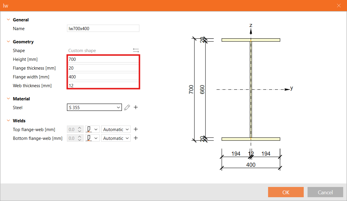
Két gerenda automatikusan hozzáadásra került. Módosítsa a B1 szerkezeti elem keresztmetszetét hegesztett I-szelvényre, és adja meg a keresztmetszet méreteit (magasság, övlemez vastagsága, valamint a gerinc szélessége és vastagsága).
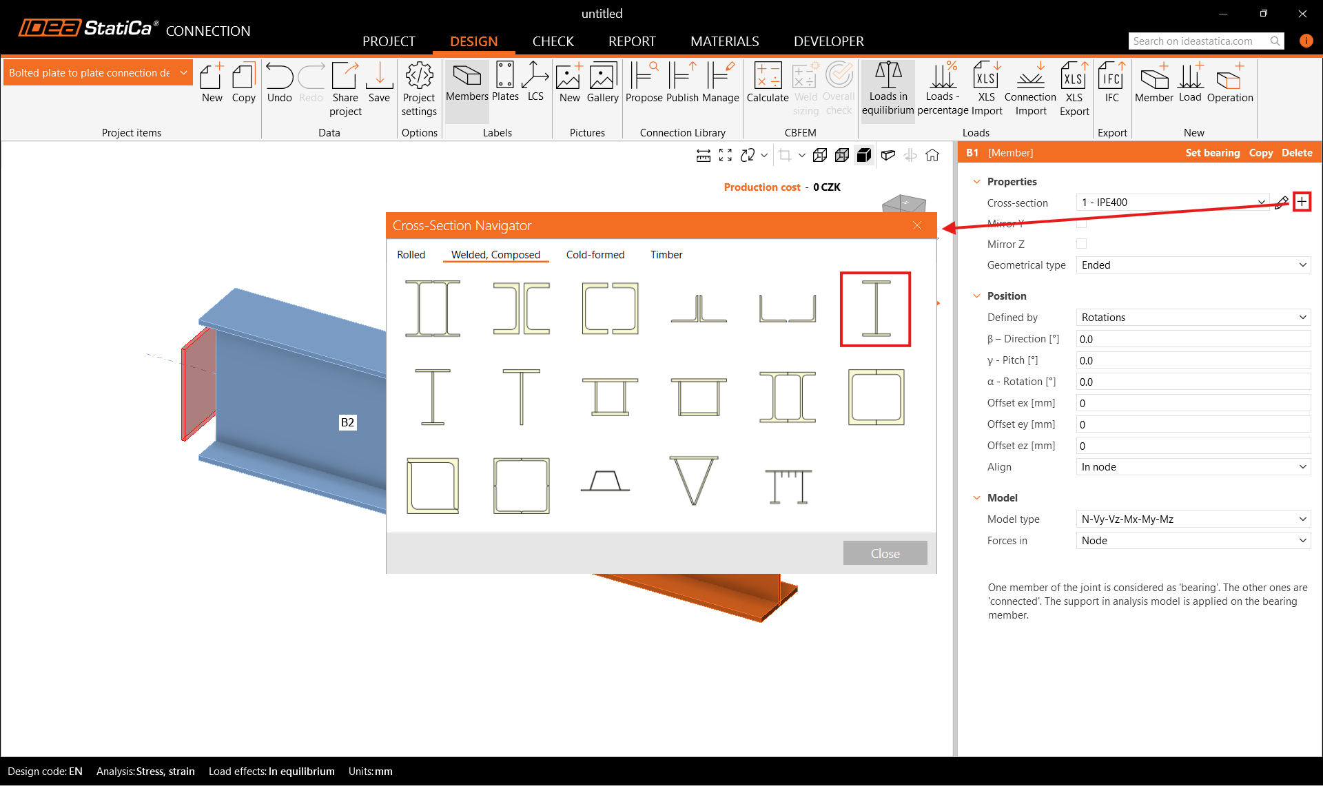
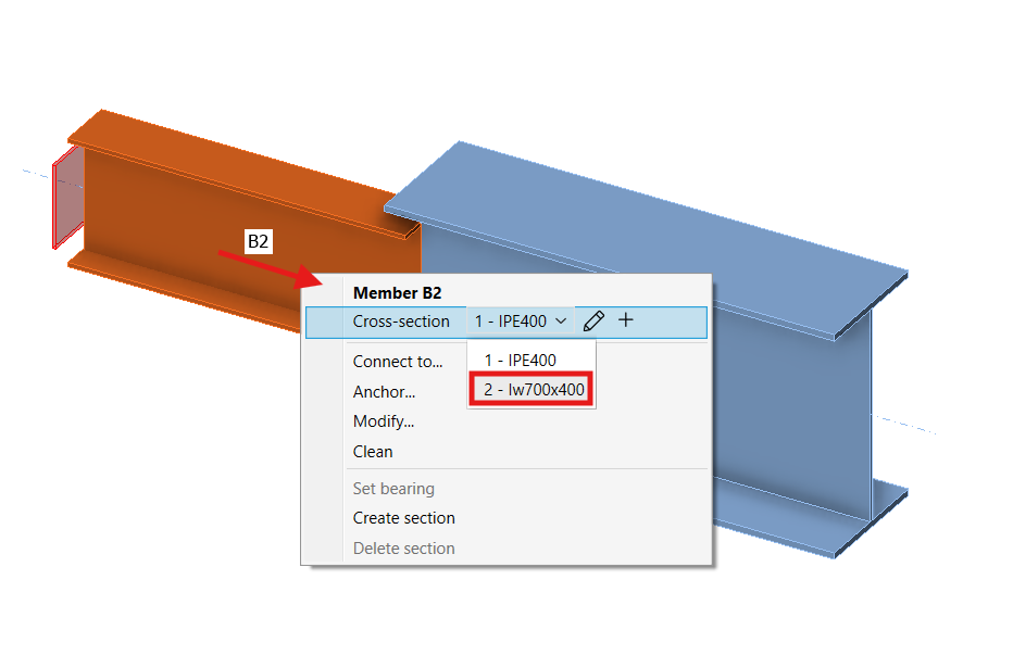
Rendelje ugyanazt a keresztmetszetet a B2 szerkezeti elemhez. Használhatja a jobb gombos menüt a 3D nézetben, vagy a legördülő menüt a paraméterek fülön.
3 Teherhatások
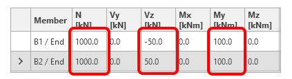
Egy teherhatás automatikusan generálódott. Adja meg a belső erők értékeit a táblázatban mindkét szerkezeti elemre.
4 Tervezés
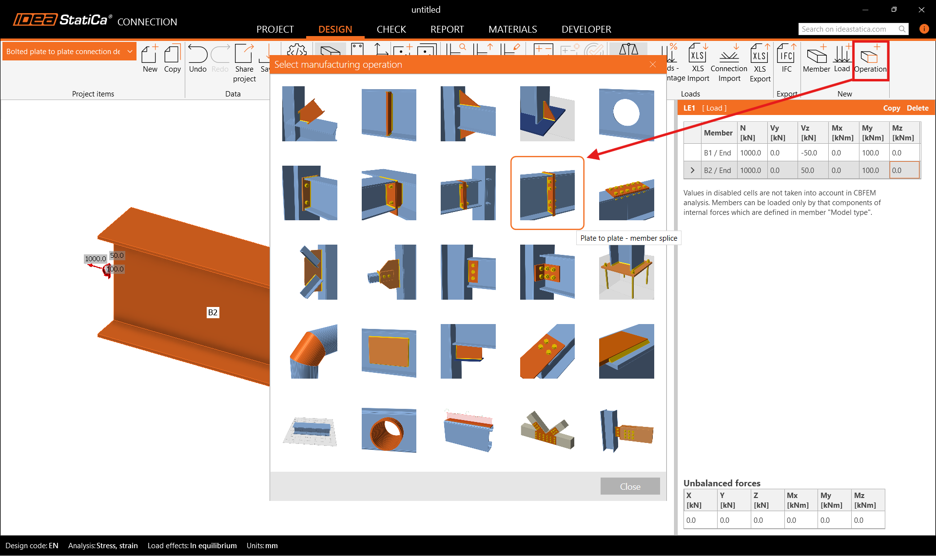
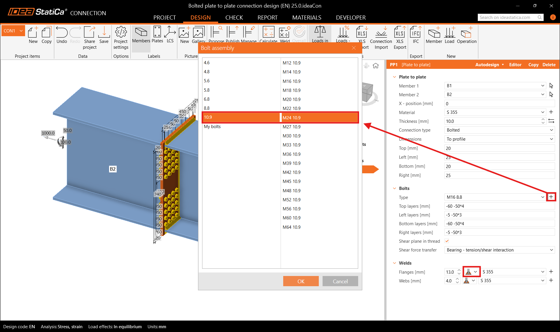
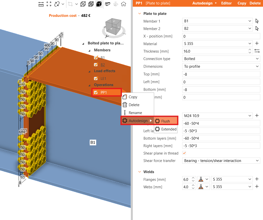
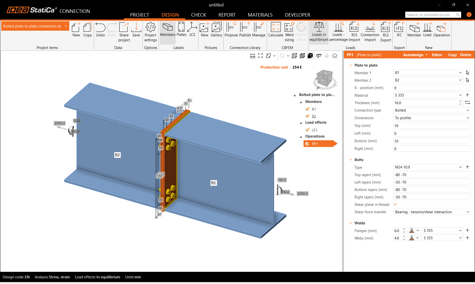
Először adja hozzá a Lemez-lemez – szerkezeti elem toldás gyártási műveletet. Módosítsa a lemez vastagságát és méreteit. Állítsa be a csavar típusát M24 10.9-re.
Ezután kattintson jobb gombbal a PP1 műveletre, és navigáljon az Autodesign és Flush lehetőségre egy javasolt kezdeti kapcsolattervezés létrehozásához.
5 Ellenőrzés
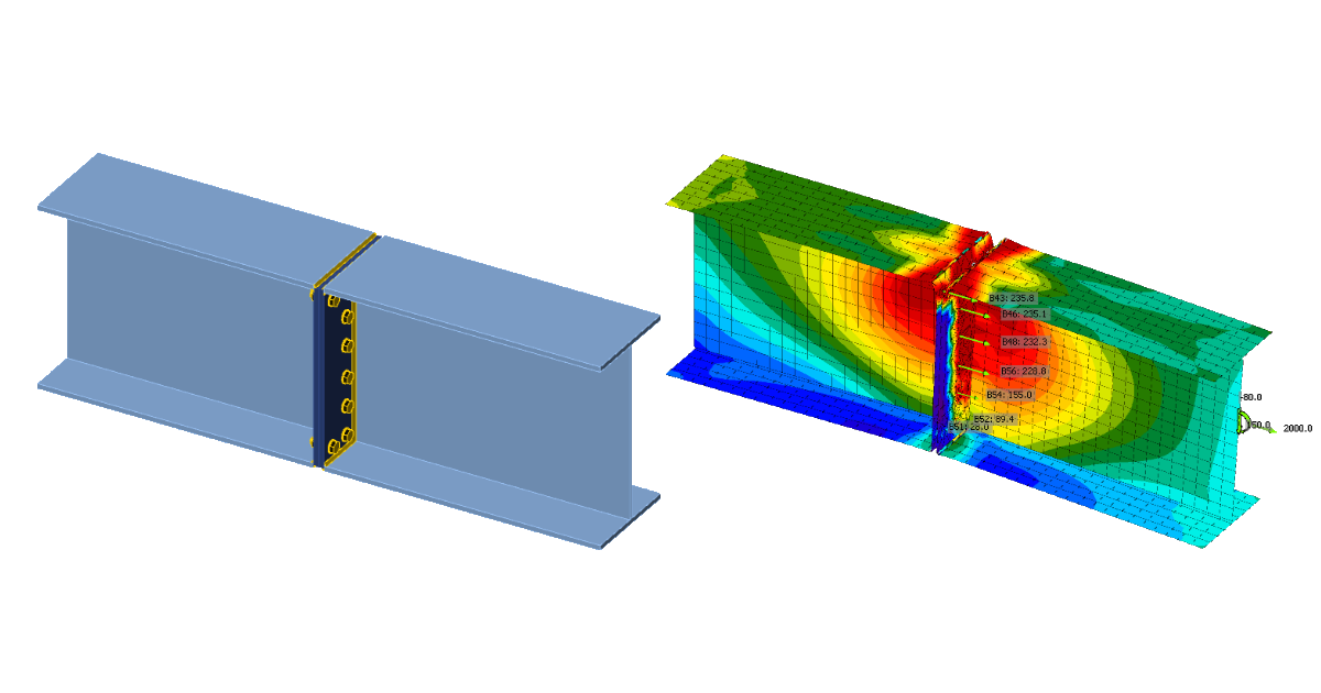
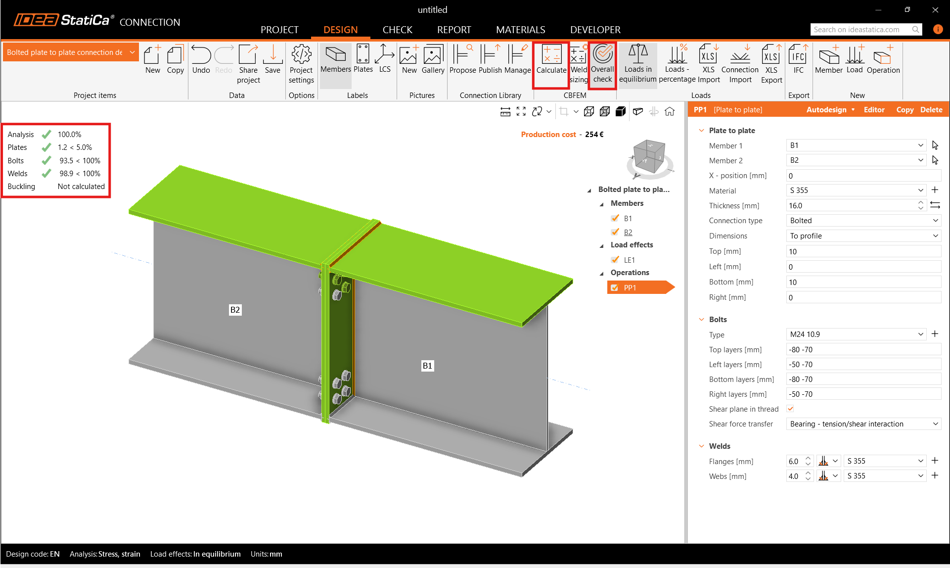
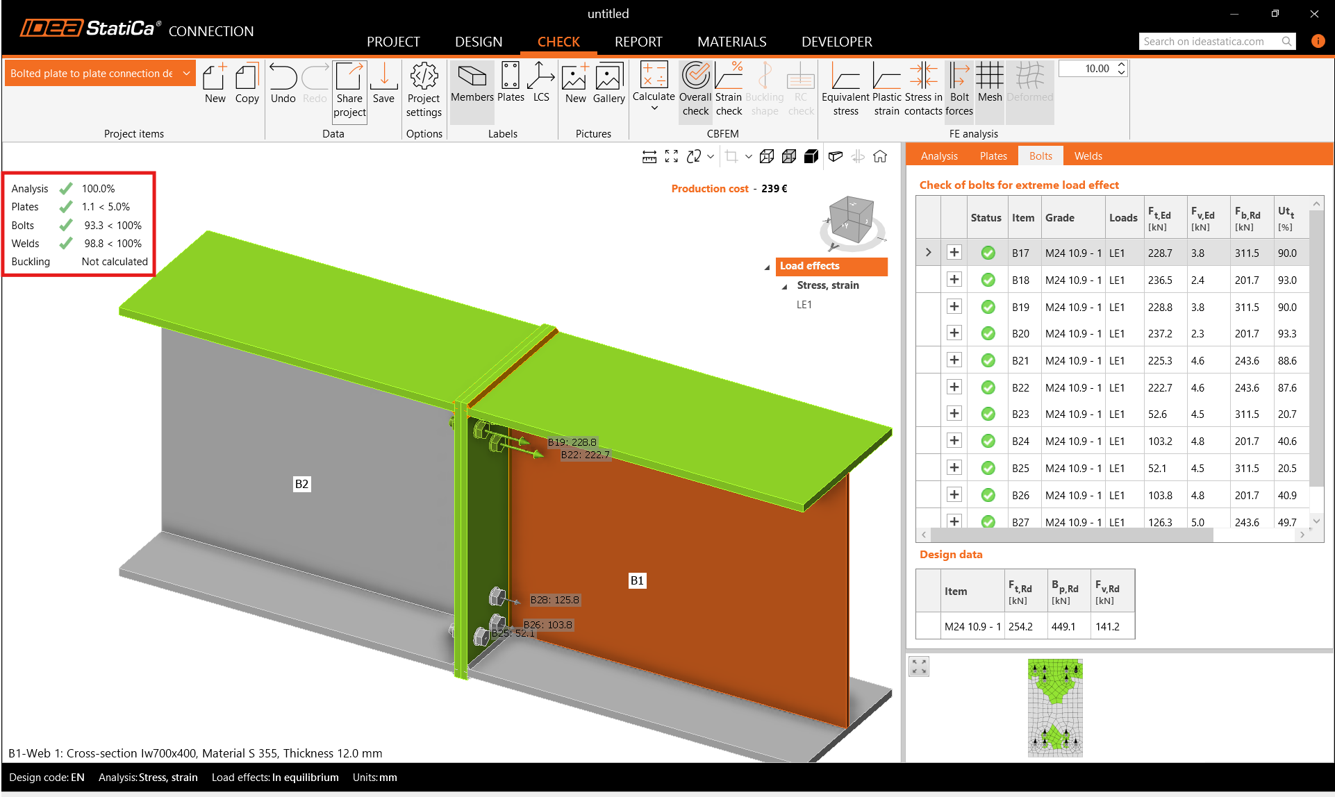
Indítsa el a CBFEM-alapú analízist a szalagon lévő Számítás gombra kattintva. Az analízismodell automatikusan generálódik, a számítás elvégzésre kerül, és az átfogó ellenőrzési eredményeket közvetlenül láthatja a nézet bal felső sarkában.
Részletesebb eredmények az Ellenőrzés fülön jeleníthetők meg. Aktiválja a Képlékeny alakváltozás, Csavarerők, Háló, és Deformált alak megjelenítését a szalagon, hogy teljes képet kapjon a modellben zajló folyamatokról.
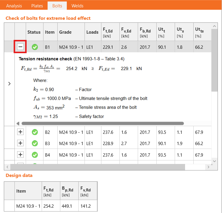
Az egyedi eredmények a megfelelő táblázatokban ellenőrizhetők. Pl. nyissa meg a Csavarok fület az egyes csavarok kihasználtságának megtekintéséhez. Láthatja, hogy egyes csavarok szinte nincsenek igénybe véve, és eltávolíthatók a tervezés optimalizálása érdekében.
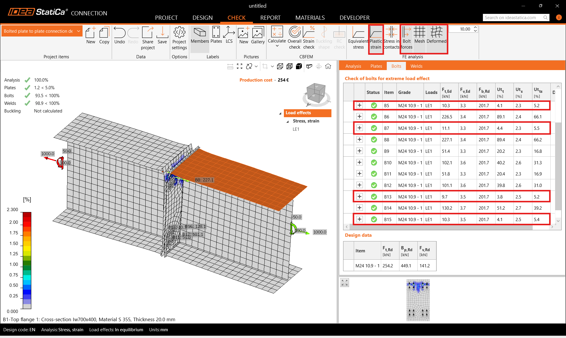
A csavar-ellenőrzési egyenleteket is megtekintheti a kibontott menüben.
6 Optimalizálás
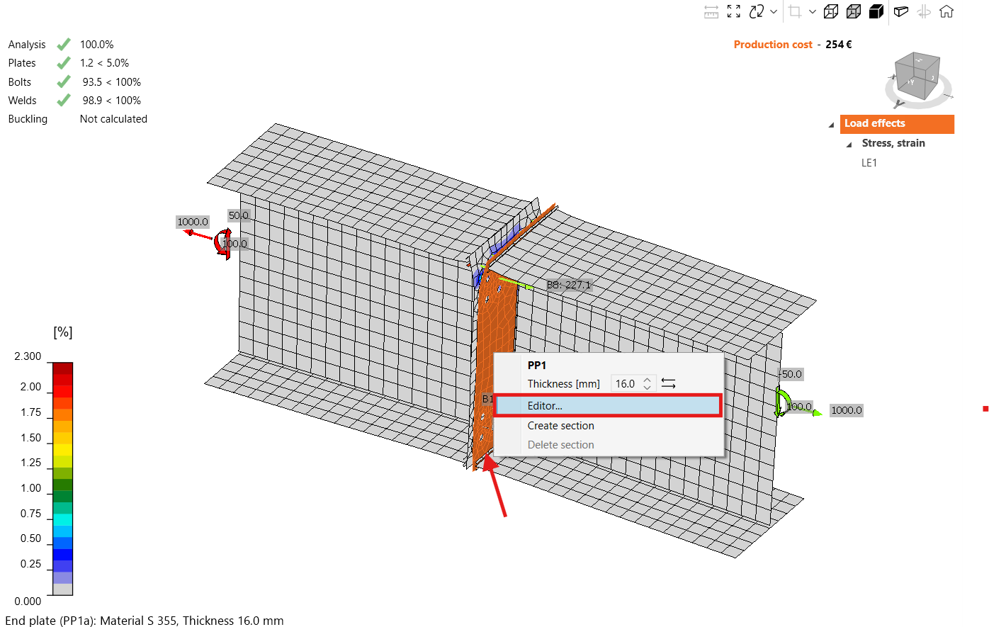
Az IDEA StatiCa Connection lehetővé teszi a tervezés egyszerű optimalizálását. Az öszzekötő lemez szerkesztőjében eltávolíthatja a felesleges csavarokat. Kattintson jobb gombbal az összekötő lemezre, és nyissa meg a Szerkesztőt.
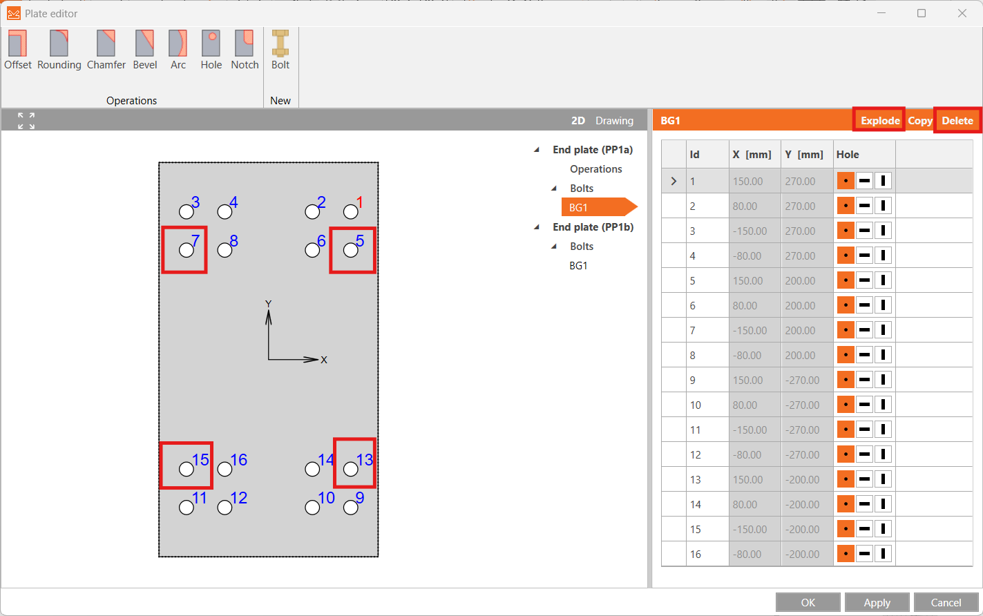
Kattintson az Explode gombra a csavarok táblázata felett, és törölje a felesleges 5, 7, 13 és 15-ös csavarokat.
Futtassa újra a Számítást, és ellenőrizze a frissített eredményeket. Az új tervezés minden ellenőrzésen megfelelt, és néhány csavart megtakarított.
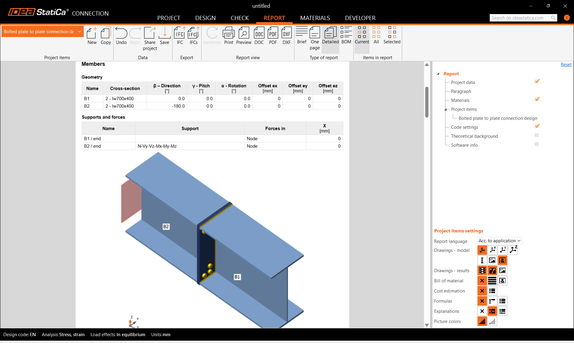
7 Jelentés
Végül áttekintheti a Jelentést. Az IDEA StatiCa teljes mértékben testreszabható jelentést kínál, amely kinyomtatható vagy szerkeszthető formátumban menthető.
Megtervezte, optimalizálta és szabványellenőrzést végzett egy csavart lemez-lemez kapcsolaton az Eurocode (EN) szerint.