
Plasticity in welds in IDEA StatiCa
Questions like:
- Is a plastic distribution in welds allowed and in accordance with the standard?
- Does the way in which welds are modeled in IDEA not lead lead to a resistance that is too high?
- How does IDEA deal with the requirements of Cl. 4.9 of EN 1993-1-8 which state that ductility of the welds should not be relied upon?
- How does IDEA deal with the requirement that welds should be sufficiently strong not to rupture before general yielding in the adjacent parent material?
In this article we provide answers to these questions.
Actual behavior of a weld
It will be helpful to first consider the real behaviour of a weld. The real stress distribution or strain distribution in a fillet weld under various load combinations is however difficult to determine precisely. Moreover, the material properties in the parent material near the weld and in the weld itself cannot be said to be homogeneous. To gain insight in the failure behaviour of welds therefore, a large number of experimental tests have been carried out worldwide.
Consider for example the following lap joint which is loaded in longitudinal direction. Similarly to bolted connections that are loaded in longitudinal direction, the stress distribution will not be uniform. Nevertheless, qualitatively one can indicate how the stress distribution would be. The highest stresses occur at the ends
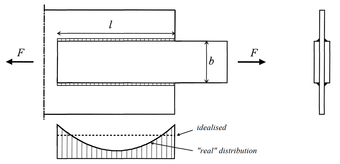
Figure 1 - Non-uniform distribution of shear stresses in a lap joint
When increasing the load further it appears that the weld does exhibit deformation capacity, and that local yielding can occur (Figure 2).
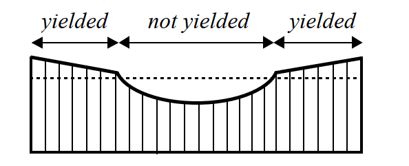
Figure 2 - Non-uniform stress distribution of shear stresses with local yielding in a lap joint
Eurocode method
Different weld configurations and load combinations may lead to different stress distributions. A semi-empirical approach was chosen as a basis for the design calculation rules from the Eurocode. Instead of checking the failure mechanism at a micro scale, the welds as a whole are checked on a macroscale. A simplified failure model was assumed, based on plasticity. By calculating back to the experimental test results a failure criterion (weld formula) was determined.
EN 1993-1-8 Cl. 4.5.3 describes two methods for the determination of the design resistance of fillet welds, the Directional method and the Simplified method. The Simplified method is a simplified method of the Directional method. In the Directional method, the forces that are transmitted by a unit length of weld are resolved into components parallel and transverse to the longitudinal axis of the weld and normal and transverse to the plane of its throat. The design value of the resistance of the weld shall be sufficient if the following equations are both satisfied:
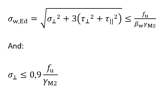
Where:
| σ⊥ | the normal stress perpendicular to the throat |
| τ⊥ | the shear stress perpendicular to the axis of the weld |
| τ || | the shear stress parallel to the axis of the weld |
| fu | the nominal ultimate tensile strength of the weaker part joined |
| βw | the correlation factor depending on the tensile strength of parent material |
| γM2 | partial safety factor for bolts and welds = 1.25 |
In the weld calculation of statically loaded structures it is then allowed to assume a uniform stress distribution over the thickness and along the length of the weld. Here it is also implicitly assumed however that plastic strains can occur to make redistribution of stresses possible. The needed deformation capacity increases as the weld length increases. The ultimate strain is still considered limited however, thus in certain situations one will have to take into account an effective width beff, for example in a joint where a transverse plate (or beam flange) is welded to a supporting unstiffened flange of an I-profile (Figure 3).
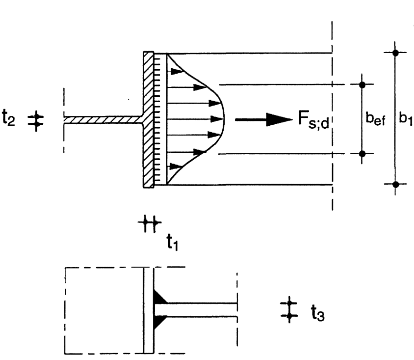
Figure 3 - Effective width of an unstiffened T-joint
CBFEM method
By contrast, in the CBFEM (Component Based Finite Element Model) approach that is used in IDEA StatiCa, a weld consists of multiple smaller elements next to each other. The weld thickness, position and orientation of the weld is taken into account. Stresses and strains in each element may vary from each other. Therefore, in the model a non-uniform stress distribution develops automatically which is more realistic than the idealised uniform stress distribution according to the codes (Figure 4).
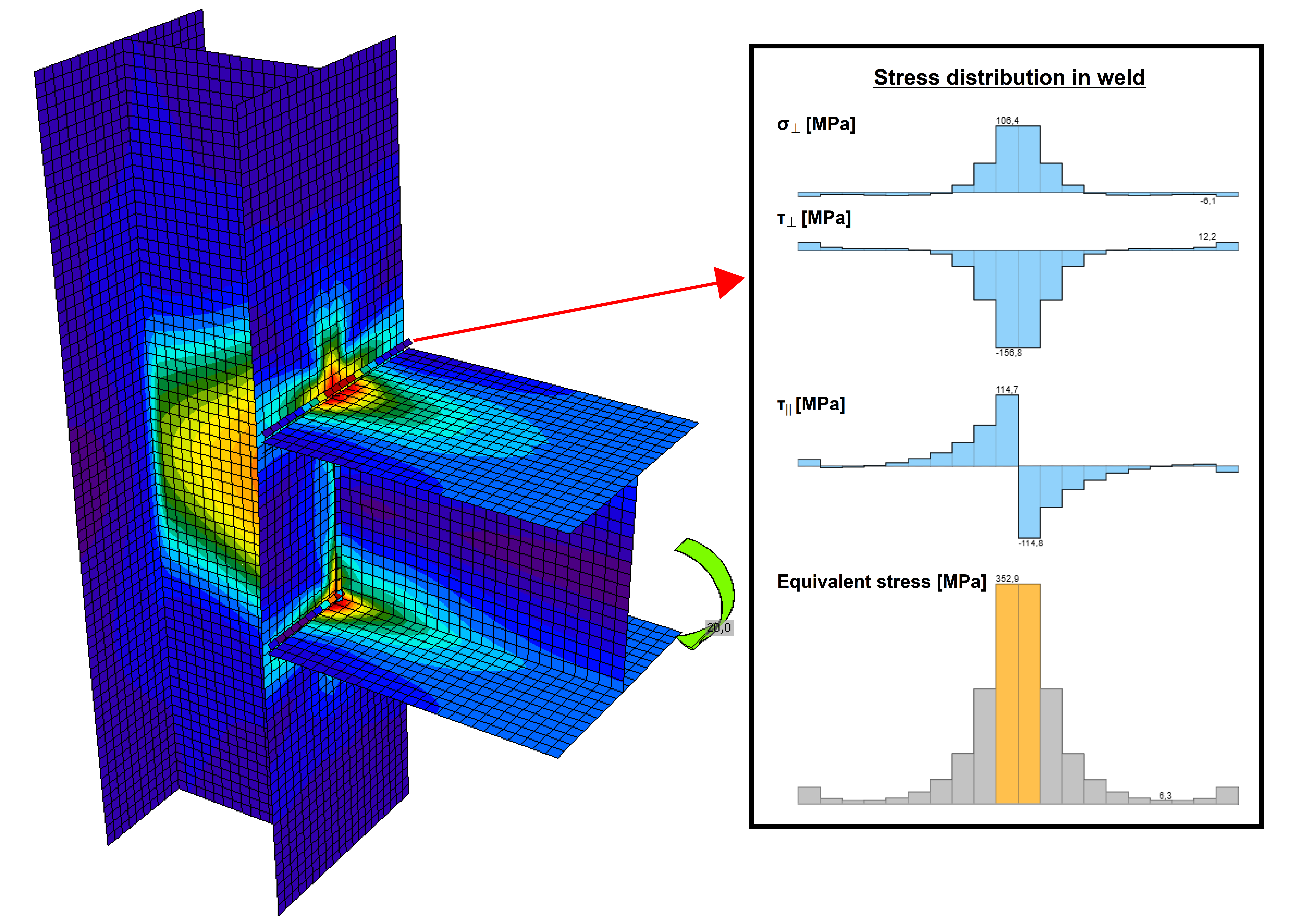
Figure 4 -Stresses in plates and welds in a welded beam to column connection IDEA
The aim of the applied material model in IDEA is however still not to capture reality perfectly. Residual stresses or weld shrinkage are neglected. The material model with its plastic limit strain value is chosen such that the total resistance of the weld in an IDEA model matches well with the resistance according to the codes. To achieve this, IDEA StatiCa has carried out many validations. In the CBFEM book (written by prof. Frantisek Wald et al. of Czech Technical University in Prague) and in subsequent research, a large number of comparisons have been made between different types of welds calculated in IDEA and calculated according to the codes or welds loaded in experiments (see Figure 5). On our website many validation documents can be found on this topic - support center verifications
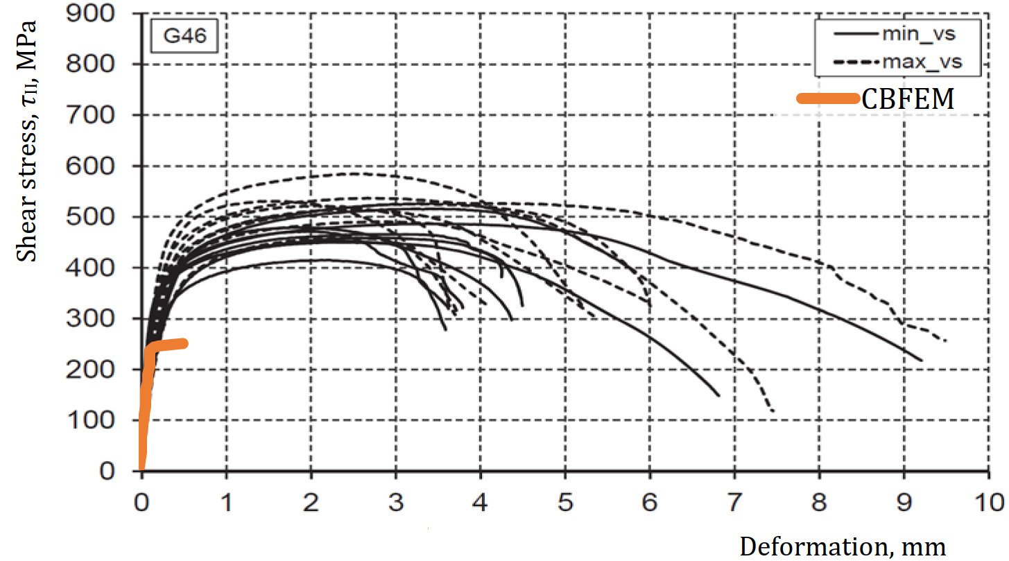
Figure 5 - Shear stress - deformation diagrams from experiments by Kleiner (2018) compared to CBFEM
This shows that the strain limit that is used leads to a safe total resistance of the weld which also matches well with the resistance calculated according to the relevant codes. This is the reason why a plastic redistribution in welds in the IDEA model is considered acceptable. Without plasticity in the welds, one could never come close to the resistance calculated by hand according to the codes.
Additional requirements from EN 1993-1-8 art. 4.9
EN 1993-1-8 in Cl. 4.9(4)-(6) further states additional requirements for welds in joints. The idea behind these rules is that a joint should be prevented to fail without sufficient warning. Even if one can show that plastic strains can occur in welds, and that the weld is in principle sufficiently strong to resist the occurring forces which are determined in a general (static) calculation, it might still be the case that the occurring forces are larger than expected and could lead to failure of the joint as a whole without sufficient warning. This is because the total elongations in a weld may still be small in an absolute sense. Sufficient warning effect may then be obtained by designing the joint in such a way that the connected plate can yield before the weld ruptures. This can be achieved by applying a minimum weld thickness to plate thickness ratio. Therefore, IDEA StatiCa includes detailing checks to verify whether a weld in the model has a sufficient weld thickness for a given plate thickness.
The specific rule that IDEA has implemented for this is based on Cl. 6.9(4) of the concept version of the upcoming new Eurocode (FprEN 1993-1-8:2023(E)) which states that to satisfy sufficient ductility, the weld must be designed in such a way that its resistance is at least equal to:
- 1.1 fy/fu times the design resistance of the weakest connected plate
- but need not be more than the design resistance of the weakest connected plate
Assuming the following standard T-joint example (Figure 6):
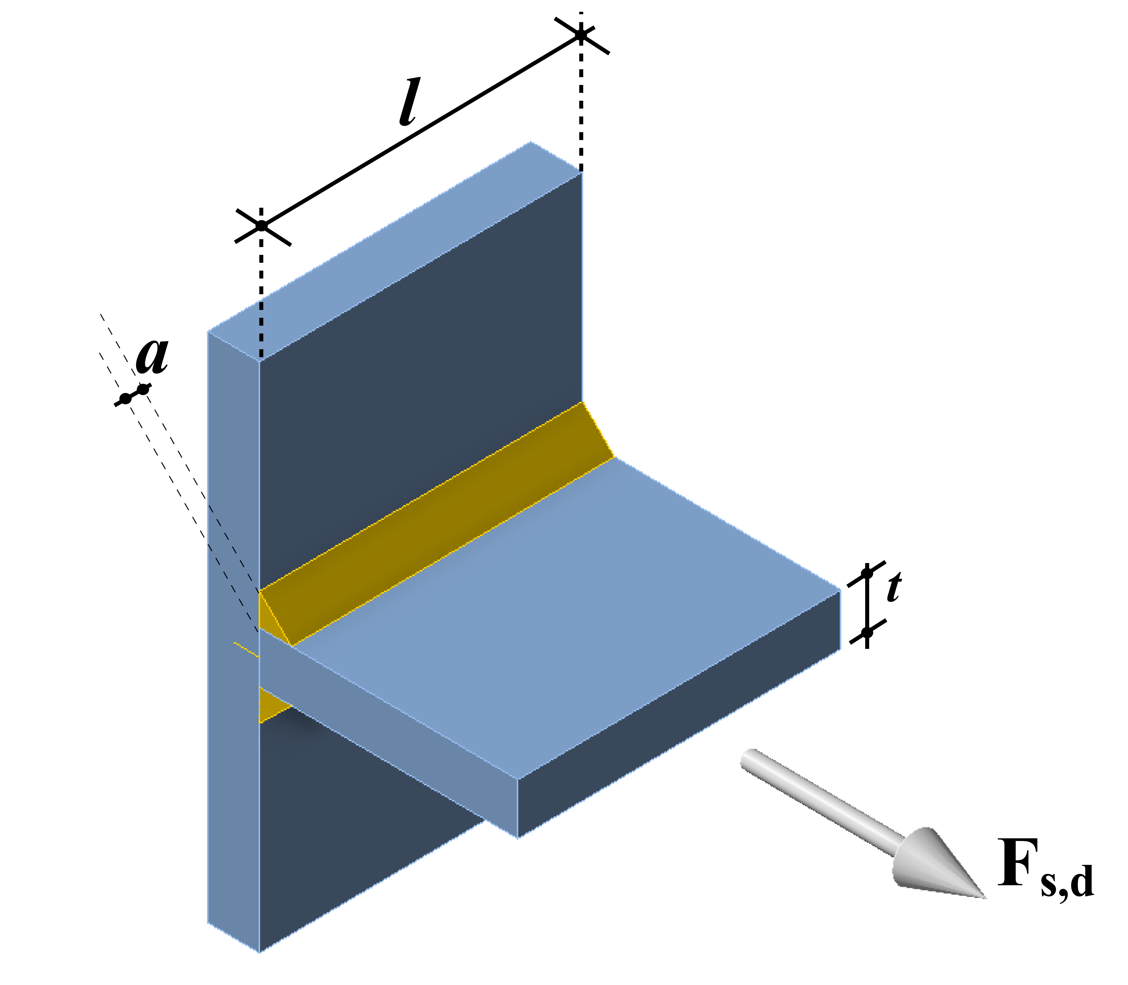
Figure 6 - T-joint with normal force acting on the connected plate equal to the yield force of the plate
where the magnitude of Fs,d is chosen such that Fs,d = fy,plate ∙ t ∙ l, This leads to the derivation of the following formula used for the detailing check in IDEA for double-sided fillet welds:
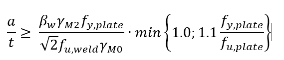
Where:
| a | weld thickness |
| t | thickness of the connected plate |
| fy,plate | yield strength of the connected plate |
| fu,plate | tensile strength of the connected plate |
| fu,weld | tensile strength of the weld |
| βw | correlation factor depending on the tensile strength of the parent material |
| γM2 | partial safety factor for bolts and welds = 1.25 |
| γM0 | partial safety factor for plate resistance = 1.0 |
For the following standard steel grades this leads to the following minimum weld thickness – plate thickness ratios (Table 1).
Table 1 - Minimum weld thickness for ductility
| Steel grade | 1.1 ∙ fy,plate/fu,plate | Minimum weld thickness |
| S235 | 0.72 | a ≥ 0.33 ∙ t |
| S275 | 0.70 | a ≥ 0.34 ∙ t |
| S355 | 0.80 | a ≥ 0.46 ∙ t |
For single-sided fillet welds the derived value must be multiplied by 2. The user of IDEA will receive a warning when the applied weld thickness does not satisfy the minimum value (Figure 7). The user shall also receive an error message when welds are applied with throat thickness smaller than 3.0 mm which is not allowed according to EN 1993-1-8 Cl. 4.5.2(2).
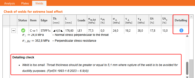
Figure 7 - Warning when applying too small weld thickness in IDEA
Nevertheless, there might be situations where one can argue that it is not necessary to satisfy the minimum weld thickness requirement for ductility purposes. For example, welds of a column base plate connection which mainly transmit compression forces. Or if one could show that some other part in the global structure exists that would fail with sufficient warning anyway. The program should always be considered as a tool, it is up to the engineer to use his or her engineering judgement to make an informed decision about the final design.
