Étude de vérification : Assemblages en cisaillement avec poutres à extrémité réduite (AISC)
Mark D. Denavit et Rick Mulholland ont préparé cet exemple de vérification dans le cadre d'un projet commun entre l'Université du Tennessee et IDEA StatiCa.
Description
Cette étude présente une comparaison entre les résultats de la méthode des éléments finis basée sur les composants (CBFEM) et les méthodes de calcul traditionnelles utilisées dans la pratique américaine pour les assemblages en cisaillement simple entre une poutre principale et une poutre à extrémité réduite. L'étude se concentre sur les états limites spécifiquement associés aux extrémités réduites des poutres. Les poutres à extrémité réduite simple (extrémité réduite sur la semelle supérieure uniquement) et les poutres à extrémité réduite double (extrémité réduite sur les semelles supérieure et inférieure) sont évaluées.
Les calculs traditionnels ont été effectués conformément aux dispositions de dimensionnement par facteurs de charge et de résistance (LRFD) de la norme AISC Specification (2016), avec les états limites pour les poutres à extrémité réduite tels que décrits dans la Partie 9 du Manuel AISC 15e édition (2017) et Dowswell (2018).
Les résultats CBFEM ont été obtenus avec IDEA StatiCa version 22.1. Les charges maximales admissibles ont été déterminées de manière itérative en ajustant la valeur de la charge appliquée à une valeur que le programme juge sûre, mais si elle est augmentée d'une faible quantité (0,1 kip), le programme la jugerait non sûre en dépassant la limite de déformation plastique de 5 %, en dépassant un taux de travail de 100 % pour les boulons ou les soudures, ou avec un rapport de flambement inférieur à 3,0. Les analyses de type DR peuvent aider à identifier les charges maximales admissibles. Cependant, une certaine approximation est faite dans l'évaluation de la résistance de calcul de l'assemblage ; par conséquent, tous les résultats de ce rapport sont basés sur une analyse de type EPS.
Poutres à extrémité réduite simple
La résistance des poutres à extrémité réduite simple a été évaluée en fonction des quatre paramètres suivants :
- Longueur de l'extrémité réduite
- Épaisseur de l'âme
- Rayon de l'angle de l'extrémité réduite
- Position de la force appliquée par rapport au nœud
Pour l'étude de la longueur de l'extrémité réduite et de la position de la force appliquée par rapport au nœud, deux types d'assemblage différents ont été utilisés : un assemblage à double cornière entièrement boulonné et un assemblage à platine d'extrémité en cisaillement boulonné/soudé. Seul l'assemblage à platine d'extrémité en cisaillement boulonné/soudé a été utilisé pour l'évaluation de l'épaisseur de l'âme et du rayon de l'angle de l'extrémité réduite.
L'état limite de flambement local en flexion de l'âme (tel que décrit dans la Partie 9 du Manuel AISC) et les états limites relatifs à la configuration spécifique de l'assemblage décrits dans les sections suivantes ont été évalués et comparés aux résultats de l'analyse CBFEM d'IDEA StatiCa.
Effet de la longueur de l'extrémité réduite (assemblage à double cornière entièrement boulonné)
La configuration de cet exemple correspond à celle de l'Exemple II.A-4 des AISC Design Examples v15.1 (AISC, 2019), avec la double cornière modifiée pour être conforme à l'ASTM A529 Gr 55 (Fy = 55 ksi et Fu = 70 ksi). La modification du matériau de la cornière a été effectuée pour mettre en évidence les états limites liés à l'extrémité réduite de la poutre. Le point d'application de la force est fixé à la face de l'âme de la poutre principale et un type de modèle N-Vy-Vz-Mx-My-Mz a été utilisé pour la poutre. Une vue tridimensionnelle de l'assemblage est présentée à la Figure 1.
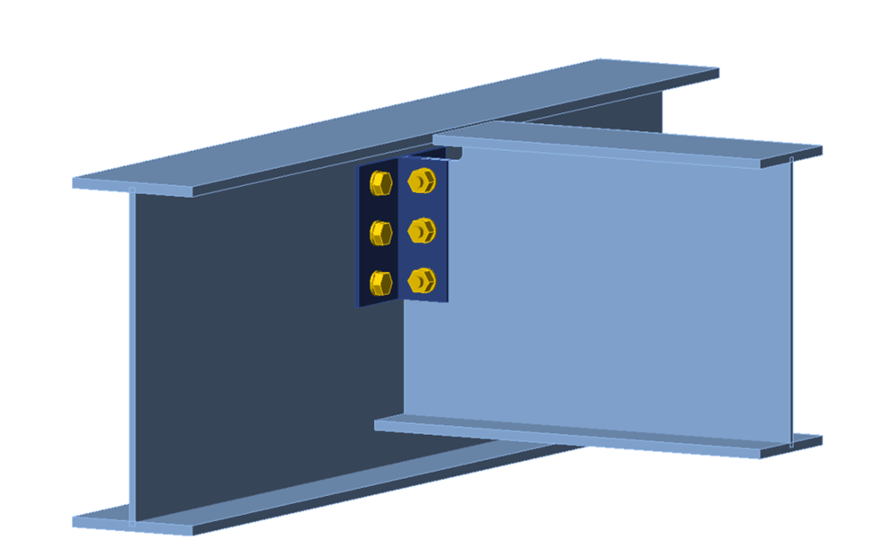
Figure 1 Vue tridimensionnelle de la poutre à extrémité réduite simple (assemblage à double cornière entièrement boulonné)
Les états limites évalués pour l'âme de la poutre à extrémité réduite sont : le flambement local en flexion de l'âme, la plastification en cisaillement, la rupture en cisaillement et la rupture par arrachement en bloc. Les états limites supplémentaires pour l'assemblage sont : la rupture en cisaillement des boulons, le refoulement et l'arrachement pour le groupe de boulons entre l'âme de la poutre et la cornière, la plastification en cisaillement de la cornière, la rupture en cisaillement de la cornière, la rupture par arrachement en bloc de la cornière, ainsi que la rupture en cisaillement des boulons, le refoulement et l'arrachement pour le groupe de boulons entre la cornière et l'âme de la poutre principale.
Les calculs ont été effectués pour 10 longueurs d'extrémité réduite allant de 4 à 22 po par incréments de 2 po. Les longueurs d'extrémité réduite les plus grandes seraient rarement, voire jamais, pratiques, mais sont examinées ici pour évaluer l'état limite de flambement local en flexion de l'âme. La charge de cisaillement pondérée maximale pouvant être appliquée à l'assemblage (c'est-à-dire la résistance de l'assemblage) est présentée à la Figure 2.
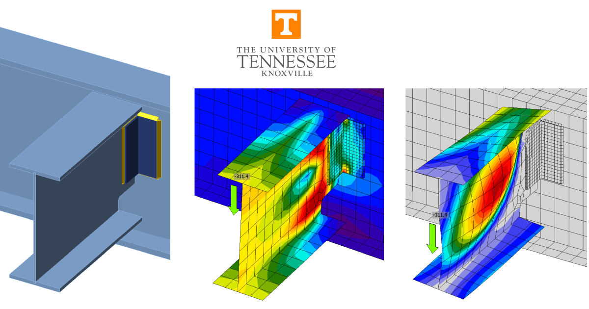
Pour les calculs traditionnels comme pour IDEA StatiCa, la résistance de l'assemblage est relativement constante pour les faibles valeurs de longueur d'extrémité réduite, puis diminue avec l'augmentation de la longueur. Pour les calculs traditionnels, les assemblages avec des longueurs d'extrémité réduite de 14 po ou moins étaient gouvernés par la rupture par arrachement en bloc de l'âme de la poutre, et le flambement local en flexion de l'âme de la poutre à extrémité réduite gouvernait les assemblages avec des longueurs d'extrémité réduite supérieures à 14 po. Pour IDEA StatiCa, les assemblages avec des longueurs d'extrémité réduite de 10 po ou moins étaient gouvernés par la limite de déformation plastique de 5 % de l'âme de la poutre, et les assemblages avec des longueurs d'extrémité réduite supérieures à 10 po étaient gouvernés par une limite de rapport de flambement de 3,0. La forme déformée par flambement pour l'assemblage avec une longueur d'extrémité réduite de 12 po est présentée à la Figure 3 ; la forme est cohérente avec le flambement local en flexion de l'âme.
La résistance de l'assemblage est inférieure pour IDEA StatiCa par rapport aux calculs traditionnels pour toute la plage de longueurs étudiée. La différence de résistance est plus grande lorsque le flambement est déterminant, en raison du caractère conservateur de la limite de rapport de flambement de 3,0. La limite de 3,0 est recommandée pour le flambement local. L'utilisation de cette limite est analogue à l'utilisation uniquement d'éléments compacts dans le dimensionnement des poutres, car le respect de cette limite permet de dimensionner sans tenir compte du flambement local. Cependant, la limite du rapport de flambement nécessaire pour éviter le flambement local dépend de la configuration de l'élément et n'a pas été spécifiquement identifiée pour le flambement local en flexion de l'âme comme elle l'a été pour d'autres types de flambement (par ex., Stabilité des goussets par analyse de flambement local et analyse matérielle non linéaire et Analyse de flambement selon l'AISC.
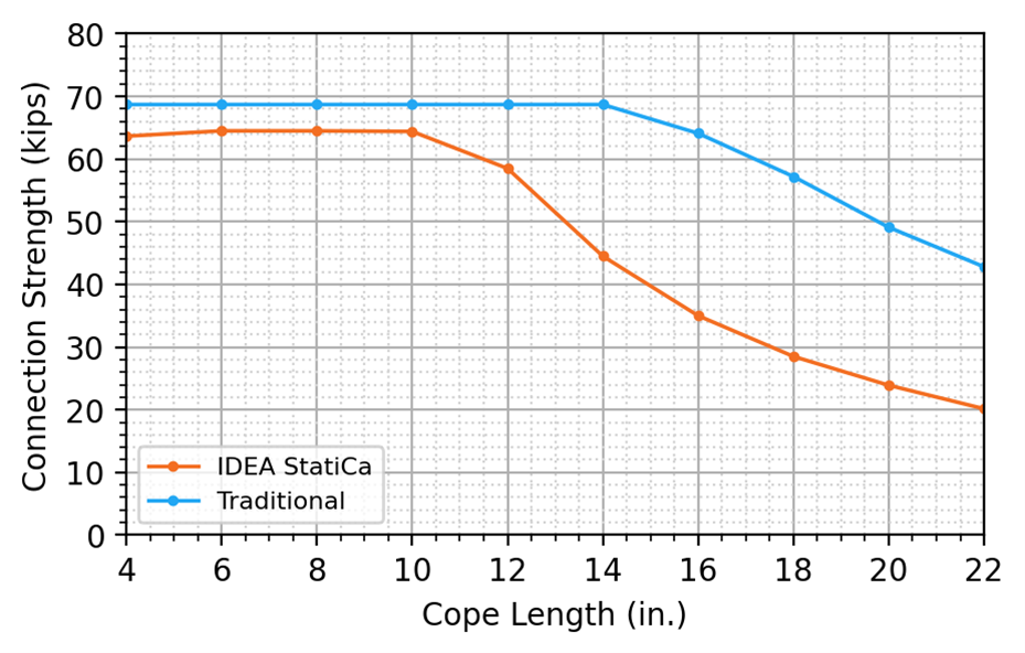
Figure 2 Résistance de l'assemblage en fonction de la longueur de l'extrémité réduite pour une poutre à extrémité réduite simple (assemblage à double cornière entièrement boulonné)
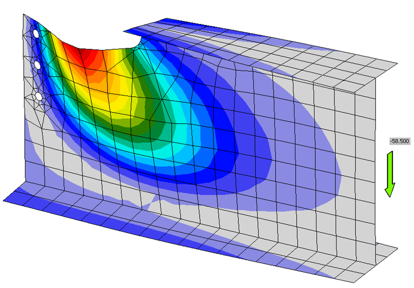
Figure 3 Forme déformée par flambement pour une poutre à extrémité réduite simple (assemblage à double cornière entièrement boulonné, longueur d'extrémité réduite de 12 po)
Effet de la longueur de l'extrémité réduite (platine d'extrémité en cisaillement boulonnée/soudée)
La poutre utilisée dans cet exemple est un W14x30 avec une profondeur d'extrémité réduite de 3 po, et la poutre principale est un W21x101 avec une largeur de semelle modifiée (c'est-à-dire réduite) pour s'adapter à des longueurs d'extrémité réduite variables. La poutre et la poutre principale sont toutes deux conformes à l'ASTM A992 (Fy = 50 ksi et Fu = 65 ksi). La platine d'extrémité mesure 6 po de large sur 8,5 po de hauteur, a une épaisseur de 3/8 po et est conforme à l'ASTM A36 (Fy = 36 ksi et Fu = 58 ksi). Le groupe de boulons est constitué d'une rangée simple de 3 boulons de chaque côté de l'âme de la poutre. Les boulons sont conformes à l'ASTM F3125 Gr A325 Groupe A avec les filets non exclus des plans de cisaillement. La poutre est soudée à la platine d'extrémité des deux côtés de l'âme de la poutre avec une soudure d'angle de 1/4 po (E70XX). Les résistances de calcul du Tableau 10-4 du Manuel AISC pour les assemblages à platine d'extrémité en cisaillement boulonnés/soudés ont été calculées en supposant que la longueur de soudure est réduite d'une taille de soudure à chaque extrémité. La raison de l'arrêt anticipé des soudures est d'éviter les entailles dans le métal de base, comme décrit dans une note d'utilisation de la Section J2.2b de la norme AISC Specification. Pour une comparaison plus cohérente, la longueur de soudure dans IDEA StatiCa a été manuellement réduite à 8 po. Le point d'application de la force a été fixé à la face de l'âme de la poutre principale et un type de modèle N-Vy-Vz-Mx-My-Mz a été utilisé pour la poutre. Une vue tridimensionnelle de l'assemblage est présentée à la Figure 4.
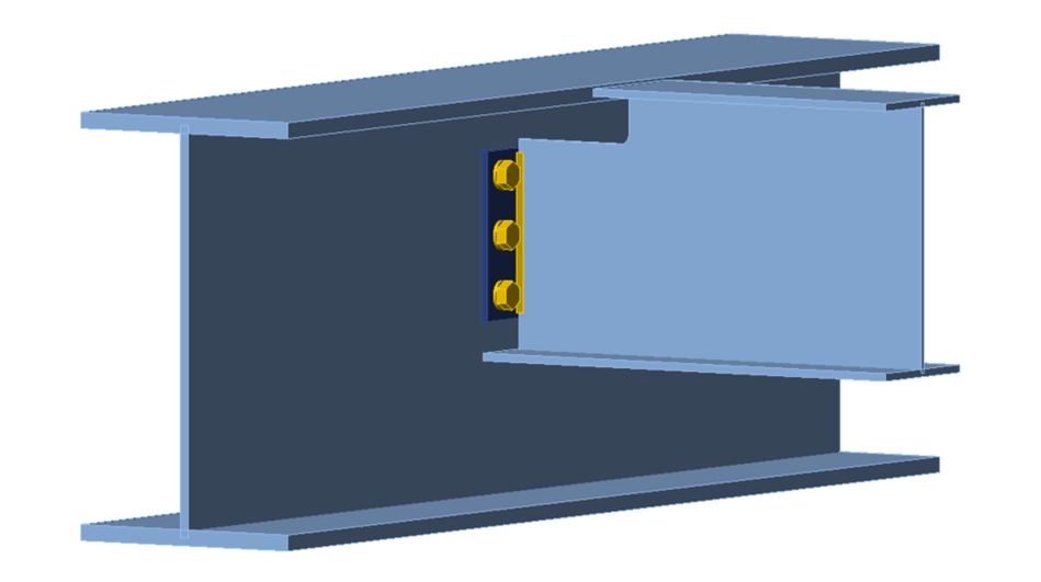
Figure 4 Vue tridimensionnelle de la poutre à extrémité réduite simple (assemblage à platine d'extrémité en cisaillement boulonné/soudé)
Les états limites évalués pour l'âme de la poutre à extrémité réduite sont : le flambement local en flexion de l'âme, la plastification en cisaillement et la résistance du métal de base (âme) à la soudure. Les états limites supplémentaires pour l'assemblage sont : la rupture de la soudure, la résistance du métal de base (platine) à la soudure, la plastification en cisaillement de la platine, la rupture en cisaillement de la platine, la rupture par arrachement en bloc de la platine et le transfert de cisaillement entre la platine et la poutre principale.
Les calculs ont été effectués pour 13 longueurs d'extrémité réduite allant de 3 à 9 po par incréments de 1/2 po. La charge de cisaillement pondérée maximale pouvant être appliquée à l'assemblage est présentée à la Figure 5. Pour les calculs traditionnels, la résistance de l'assemblage était constante pour les assemblages avec une longueur d'extrémité réduite allant jusqu'à 7 po, la résistance du métal de base de l'âme à la ligne de soudure étant déterminante. Les assemblages avec des longueurs d'extrémité réduite supérieures à 7 po étaient gouvernés par l'état limite de flambement local en flexion de l'âme. Pour l'analyse IDEA StatiCa, la résistance de la soudure gouvernait la résistance des assemblages avec des longueurs d'extrémité réduite de 3 et 3-1/2 po, et la limite de rapport de flambement de 3,0 gouvernait la résistance des assemblages avec des longueurs d'extrémité réduite supérieures à 3-1/2 po. La forme déformée par flambement pour l'assemblage avec une longueur d'extrémité réduite de 9 po est présentée à la Figure 6.
La résistance obtenue avec IDEA StatiCa est légèrement supérieure à celle des calculs traditionnels pour les assemblages avec des longueurs d'extrémité réduite de 3 et 3-1/2 po. La vérification de la résistance du métal de base de l'âme gouvernait les calculs traditionnels pour ces assemblages. IDEA StatiCa capture cet état limite avec la limite de déformation plastique de 5 %, de sorte que des différences mineures sont attendues. Cependant, pour tous les cas où l'état limite de flambement local en flexion de l'âme est déterminant, la résistance obtenue avec IDEA StatiCa est inférieure à celle des calculs traditionnels. Comme observé dans la section précédente, cela est principalement dû au caractère conservateur de la limite de rapport de flambement de 3,0.
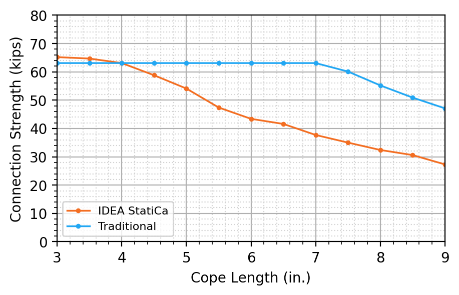
Figure 5 Résistance de l'assemblage en fonction de la longueur de l'extrémité réduite pour une poutre à extrémité réduite simple (assemblage à platine d'extrémité en cisaillement boulonné/soudé)
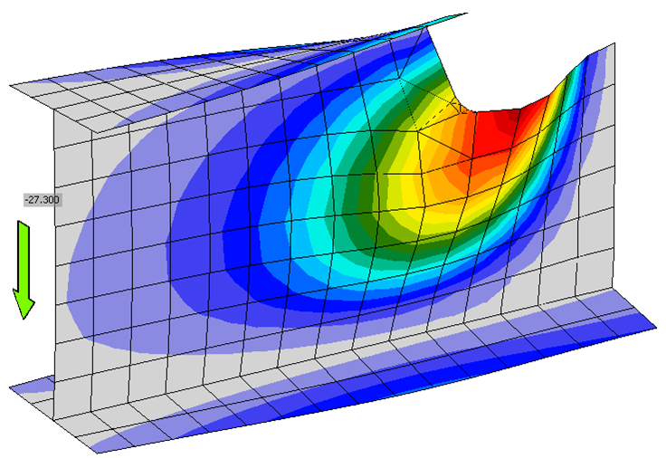
Figure 6 Forme déformée par flambement pour une poutre à extrémité réduite simple (platine d'extrémité en cisaillement boulonnée/soudée, longueur d'extrémité réduite de 9 po)
Effet de l'épaisseur de l'âme de la poutre
Pour évaluer l'effet de l'épaisseur de l'âme pour une poutre à extrémité réduite simple, la même configuration d'assemblage à platine d'extrémité en cisaillement boulonné/soudé que ci-dessus a été utilisée, avec une extrémité réduite supérieure de longueur 7-1/2 po et de profondeur 3 po. L'épaisseur de l'âme de la poutre W14x30 a été modifiée pour des valeurs allant de 1/8 à 1/2 po par incréments de 1/16 po. L'épaisseur nominale de l'âme d'un W14x30 est de 0,270 po. La charge de cisaillement pondérée maximale pouvant être appliquée à l'assemblage est présentée à la Figure 7.
Comme prévu, la résistance de l'assemblage a augmenté avec l'augmentation de l'épaisseur de l'âme, tant pour les calculs traditionnels que pour IDEA StatiCa. Pour les calculs traditionnels, l'état limite de flambement local en flexion de l'âme de la poutre à extrémité réduite était déterminant pour les assemblages avec des épaisseurs d'âme de 1/8 po à 1/4 po. Pour les assemblages avec des épaisseurs d'âme de 5/16 po à 7/16 po, la résistance du métal de base de l'âme à la soudure était déterminante, et pour une épaisseur d'âme de 1/2 po, la résistance du groupe de boulons entre la platine et l'âme de la poutre principale était déterminante. Pour l'analyse IDEA StatiCa, la limite de rapport de flambement de 3,0 était déterminante pour les assemblages avec des épaisseurs d'âme de 5/16 po ou moins, et la limite de déformation plastique de 5 % à l'angle rentrant de l'extrémité réduite était déterminante pour les assemblages avec des épaisseurs d'âme supérieures à 5/16 po. La résistance de l'assemblage obtenue avec IDEA StatiCa était conservative par rapport aux calculs traditionnels sur toute la plage étudiée.
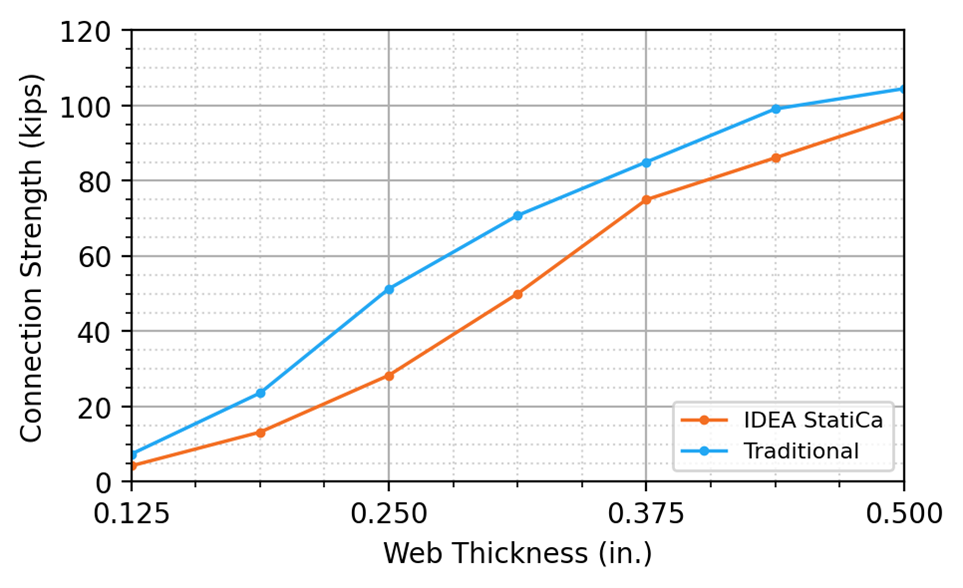
Figure 7 Résistance de l'assemblage en fonction de l'épaisseur de l'âme pour une poutre à extrémité réduite simple
Effet du rayon de l'angle de l'extrémité réduite
Les équations fournies dans la Partie 9 du Manuel AISC ne tiennent pas compte du rayon de l'angle de l'extrémité réduite ; cependant, la Section M2.2 de la norme AISC Specification stipule : « Les angles rentrants doivent être formés avec une transition courbe. Le rayon ne doit pas nécessairement dépasser celui requis pour s'adapter à l'assemblage. » Une note d'utilisation dans la même section indique : « Les angles rentrants avec un rayon de 1/2 à 3/8 po (13 à 10 mm) sont acceptables pour les ouvrages à chargement statique. »
IDEA StatiCa permet d'appliquer un rayon d'arrondi aux sections entaillées. Pour étudier l'effet du rayon d'arrondi désigné sur la résistance de la poutre à extrémité réduite, un assemblage à platine d'extrémité en cisaillement boulonné/soudé similaire à celui des deux exemples précédents a été utilisé, avec des modifications apportées à la poutre principale et aux éléments d'assemblage afin de s'assurer que la limite de déformation plastique de 5 % à l'angle rentrant de la poutre à extrémité réduite gouvernait la résistance dans IDEA StatiCa. La semelle du W21x101 a été modifiée pour avoir une largeur bf = 6 po afin de permettre une longueur d'extrémité réduite de 3 po. La platine d'extrémité a été modifiée pour avoir une largeur de 8 po et une hauteur de 11 po, avec une épaisseur de 1/2 po. Le diamètre des boulons a été augmenté à 1 po et la taille de la soudure a été augmentée à 5/8 po. Une vue tridimensionnelle de l'assemblage est présentée à la Figure 8.
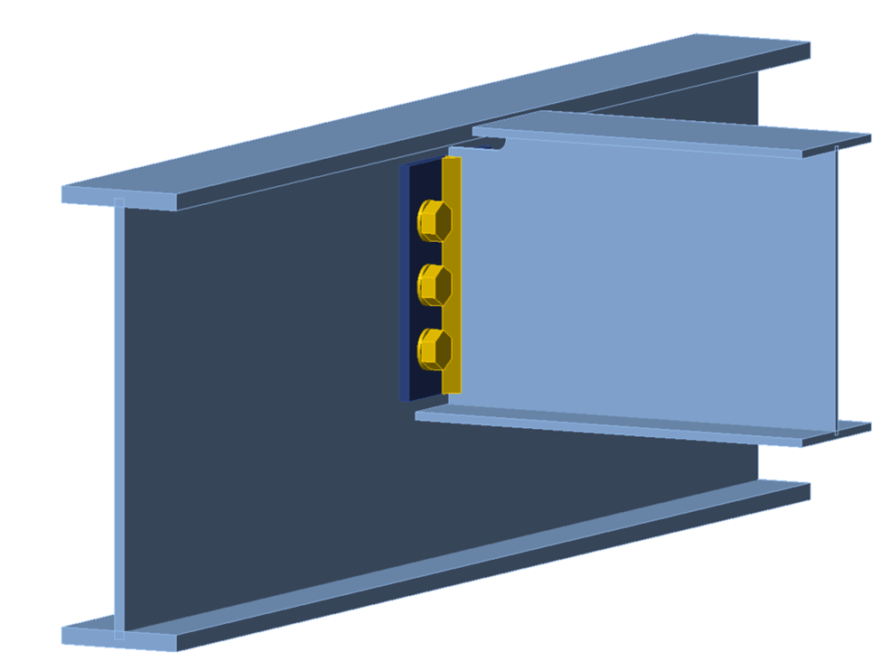
Figure 8 Vue tridimensionnelle de l'assemblage à platine d'extrémité en cisaillement utilisé pour l'analyse de l'effet du rayon de l'angle
Des analyses ont été effectuées dans IDEA StatiCa pour des dimensions de rayon d'angle variant de 0 à 1 po, en utilisant trois tailles de maillage différentes. La taille du maillage a été variée dans la configuration du code en utilisant l'option « nombre d'éléments sur l'âme ou la semelle du plus grand élément ». Pour évaluer l'effet de la taille du maillage sur la résistance de calcul, le paramètre par défaut de 8 éléments a d'abord été testé. Deux tests supplémentaires ont été effectués avec des valeurs de 16 et 32 éléments. La Figure 9 montre les distributions de déformation plastique pour des dimensions de rayon d'arrondi de 0, 1/8 et 1/2 po pour des options de maillage de 8, 16 et 32 éléments. La charge de cisaillement pondérée maximale pouvant être appliquée à l'assemblage est présentée à la Figure 10.
Pour les trois tailles de maillage testées, l'extrémité réduite avec un angle rentrant à angle droit (rayon d'arrondi = 0 po) présentait la résistance d'assemblage la plus élevée. L'introduction d'un petit rayon de 1/8 po a provoqué une diminution de la résistance. La résistance a ensuite augmenté avec l'augmentation du rayon jusqu'à 1/2 po, et au-delà de 1/2 po est restée constante avec une augmentation minimale. La taille du maillage IDEA StatiCa avait peu d'effet sur la résistance de l'assemblage pour des dimensions de rayon d'arrondi supérieures à 3/8 po.
Avec un maillage plus grossier et un petit rayon (mais non nul), les éléments à l'angle deviennent mal formés (triangles longs et étroits) comme on peut le voir à la Figure 9, car l'algorithme qui crée le maillage dans IDEA StatiCa utilise actuellement 3 segments dans le rayon quelle que soit la taille du rayon ou des éléments typiques.
L'utilisation d'un rayon d'angle rentrant approprié (par ex., 3/8 à 1/2 po pour les assemblages à chargement statique comme indiqué dans la note d'utilisation de la Section M2.2 de la norme AISC Specification) et la modélisation du rayon d'angle tel que conçu dans IDEA StatiCa constituent probablement la meilleure approche et une approche qui fonctionnera avec les paramètres de maillage par défaut.
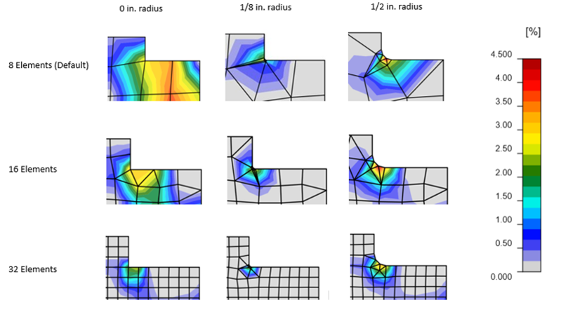
Figure 9 Distributions de déformation plastique pour différentes dimensions de rayon et tailles de maillage
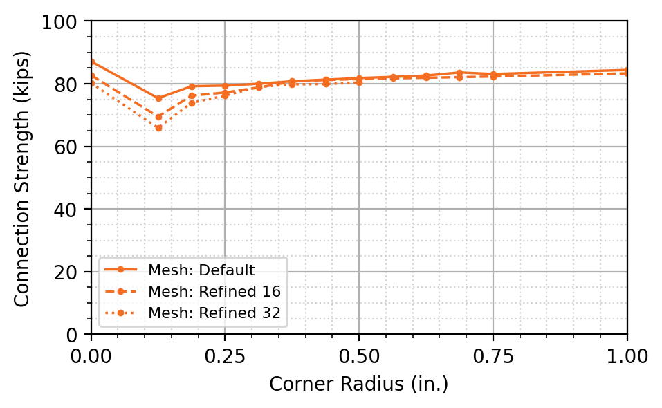
Figure 10 Résistance de l'assemblage obtenue avec IDEA StatiCa en fonction du rayon de l'angle rentrant
Effet de la position de la force appliquée
La Partie 9 du Manuel AISC définit l'excentricité de la force, e, comme la « distance entre la face de l'élément d'appui et la face de l'extrémité réduite, sauf si une valeur inférieure peut être justifiée », désignant essentiellement la face de l'élément d'appui comme le point de moment nul ou le « rotule ». IDEA StatiCa permet d'ajuster manuellement la position de la force appliquée. La position de la force appliquée peut être utilisée pour définir le point de moment nul. Pour toutes les analyses de ce rapport, à l'exception de celles décrites dans cette section, la position de la force appliquée a été fixée à la moitié de l'épaisseur de l'âme de la poutre principale à partir du nœud (c'est-à-dire la face de l'élément d'appui). Étant donné que même les assemblages en cisaillement simple présentent une certaine rigidité en rotation, la position réelle du point de moment nul dépendra de la rigidité relative de la poutre, de l'assemblage et de l'appui.
IDEA StatiCa permet également à l'utilisateur de choisir entre quatre types de modèle lors de la définition des éléments :
- N-Vy-Vz-Mx-My-Mz
- N-Vz-My
- N-Vy-Mz
- N-Vy-Vz
La désignation du type de modèle fait référence aux types de forces pouvant être appliquées à l'élément, tous les autres degrés de liberté étant bloqués. Pour évaluer l'effet de la position de la force de cisaillement appliquée sur la résistance de calcul de l'assemblage de poutre à extrémité réduite, les types de modèle N-Vy-Vz-Mx-My-Mz et N-Vy-Vz ont été analysés.
Des analyses ont été effectuées sur un assemblage à double cornière entièrement boulonné et un assemblage à platine d'extrémité en cisaillement boulonné/soudé. Ces configurations d'assemblage étaient similaires à celles utilisées dans l'évaluation précédente de la résistance en fonction de la longueur de l'extrémité réduite, avec des modifications apportées pour s'assurer que les états limites liés à l'âme de la poutre à extrémité réduite étaient déterminants. Pour l'assemblage à double cornière entièrement boulonné, une longueur d'extrémité réduite de 10 po a été utilisée, le profil de la poutre principale a été augmenté à un W21x101, le profil de la double cornière a été augmenté à un L5x5x1/2 (ASTM A529 Gr 55) de longueur 10 po, et le diamètre des boulons a été augmenté à 1 po, avec 3 boulons espacés de 3 po entre axes et une distance de bord de 2 po en haut et en bas. Pour l'assemblage à platine d'extrémité en cisaillement boulonné/soudé, une longueur d'extrémité réduite de 7-1/2 po a été utilisée, et la taille de la soudure a été augmentée à 1/2 po.
La résistance de l'assemblage en fonction de la position de la force appliquée par rapport au nœud est présentée pour l'assemblage à double cornière entièrement boulonné à la Figure 11 et pour l'assemblage à platine d'extrémité en cisaillement boulonné/soudé à la Figure 12.
Pour les deux assemblages, à double cornière entièrement boulonné et à platine d'extrémité en cisaillement boulonné/soudé, la résistance de calcul pour le type de modèle N-Vy-Vz est restée pratiquement constante avec une légère augmentation de la résistance lorsque la position de la force appliquée dépassait 3 po à partir du nœud. La limite de rapport de flambement de 3,0 gouvernait tous les tests pour le type de modèle N-Vy-Vz. Lors de l'utilisation d'un type de modèle N-Vy-Vz, la rotation à l'extrémité de l'élément éloignée de l'assemblage est bloquée et une réaction de moment se développe. Pour cet assemblage, l'utilisation du type de modèle N-Vy-Vz annule largement le choix de la position de la force appliquée. Les moments dans la poutre (y compris le point de moment nul) résultent de la rigidité relative de la poutre, de l'assemblage et de la poutre principale.
Pour le type de modèle N-Vy-Vz-Mx-My-Mz, les deux configurations d'assemblage ont présenté une augmentation de la résistance de calcul avec l'augmentation de la position de la force appliquée par rapport au nœud jusqu'à 3 po, après quoi la résistance de calcul a diminué brusquement avec l'augmentation de la distance par rapport au nœud. Pour l'assemblage à double cornière entièrement boulonné, la limite de déformation plastique de 5 % gouvernait pour les positions de force appliquée jusqu'à 3 po du nœud, après quoi la déformation plastique dans la double cornière gouvernait la résistance de calcul. Pour la platine d'extrémité en cisaillement boulonnée/soudée, la limite de rapport de flambement de 3,0 gouvernait pour les positions de force appliquée jusqu'à 3 po du nœud, après quoi la résistance des soudures gouvernait la résistance de calcul. À mesure que la position de la force par rapport au nœud augmente, le moment à la section critique pour le flambement local en flexion de l'âme diminue, permettant une charge plus importante. Cependant, dans le même temps, le moment à l'assemblage augmente, les sollicitations sur l'assemblage devenant finalement déterminantes.
Le type de modèle N-Vy-Vz peut être considéré comme plus physiquement précis pour certaines longueurs de poutre, car le point de moment nul résulte naturellement de la rigidité relative de la poutre, de l'assemblage et de la poutre principale, au lieu d'être supposé. La différence de résistance de l'assemblage entre les deux modèles est de 14 % pour l'assemblage à double cornière entièrement boulonné et de 3 % pour l'assemblage à platine d'extrémité en cisaillement boulonné/soudé, le type de modèle N-Vy-Vz donnant une résistance d'assemblage plus élevée dans les deux cas lorsque la position de la force est définie à la face de l'appui.
Les formes déformées pour un assemblage à double cornière entièrement boulonné pour les deux types de modèle, dans les cas de la force appliquée à la face de l'appui et à 3 po du nœud, sont présentées à la Figure 13. Avec le type de modèle N-Vy-Vz-Mx-My-Mz et la force à la face de l'appui, la poutre se défléchit vers le haut. Bien que cette déformation ne soit pas réaliste, la distribution des forces pour ce cas est la plus cohérente avec les hypothèses décrites dans la Partie 9 du Manuel AISC.
L'utilisation d'hypothèses autres que celle du point de moment nul situé à la face de l'appui est autorisée en dimensionnement ; cependant, le moment sur l'élément d'appui (qui augmente à mesure que le point de moment nul s'éloigne de la face de l'appui) doit être pris en compte lors du dimensionnement de l'élément d'appui.
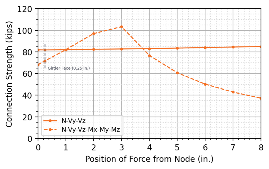
Figure 11 Résistance de l'assemblage obtenue avec IDEA StatiCa en fonction de la position de la force appliquée par rapport au nœud (assemblage à double cornière entièrement boulonné)
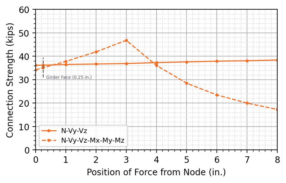
Figure 12 Résistance de l'assemblage obtenue avec IDEA StatiCa en fonction de la position de la force appliquée par rapport au nœud (assemblage à platine d'extrémité en cisaillement boulonné/soudé)
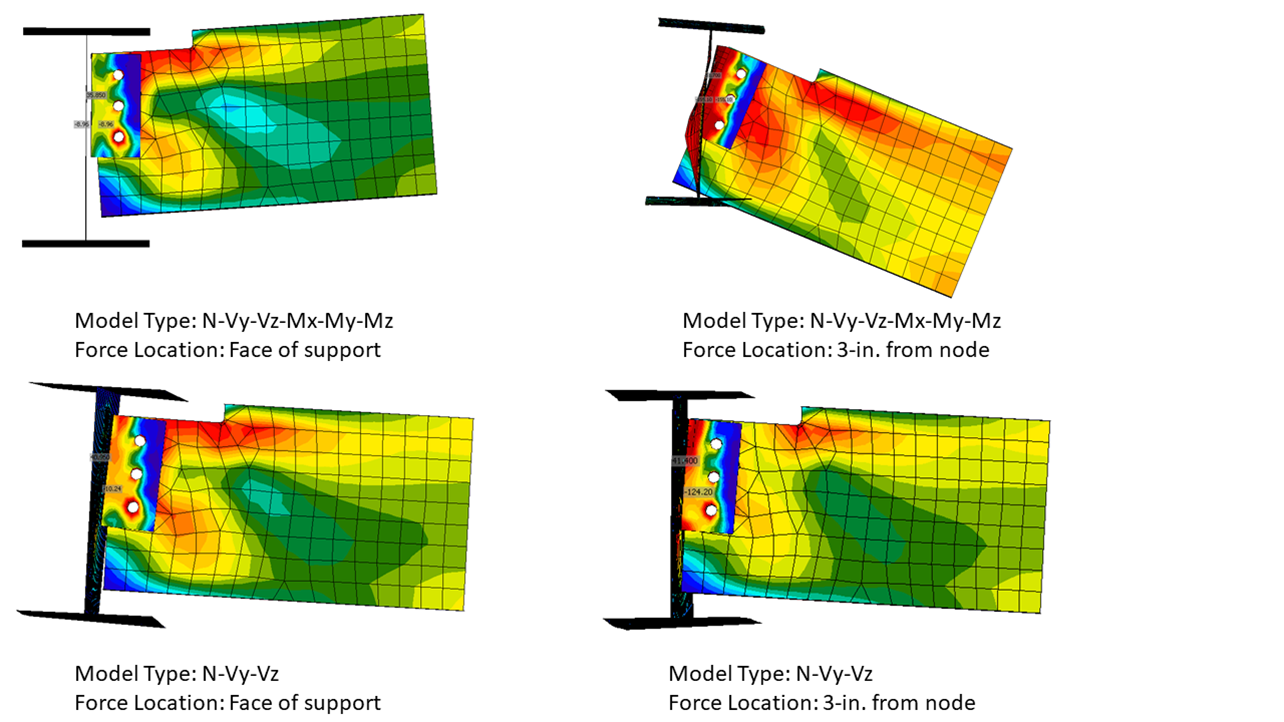
Figure 13 Comparaison des formes déformées pour une poutre à extrémité réduite simple (assemblage à double cornière entièrement boulonné). Facteur d'échelle = 3,0.
Poutres à extrémité réduite double
La résistance de calcul des poutres à extrémité réduite double a été évaluée en fonction de dimensions variables de longueur et de profondeur d'extrémité réduite, avec une extrémité réduite de longueur égale en semelle inférieure et supérieure.
La Partie 9 du Manuel AISC recommande que la résistance en flexion d'une poutre à extrémité réduite sur les semelles supérieure et inférieure soit déterminée conformément à la Section F11 de la norme AISC Specification, en utilisant un facteur de modification du déversement modifié, Cb. Lorsque l'extrémité réduite inférieure est égale ou supérieure à la longueur de l'extrémité réduite supérieure, Cb est calculé comme suit :
\[C_b=\left [ 3+\ln \left ( \frac{L_b}{d} \right ) \right ] \left ( 1-\frac{d_{ct}}{d} \right ) \ge 1.84 \]
où :
- \(C_b\) – facteur de modification du déversement
- \(L_b = c_t\)
- \(c_t\) – longueur de l'extrémité réduite supérieure
- \(d\) – hauteur de la poutre
- \(d_{ct}\) – profondeur de l'extrémité réduite à la semelle supérieure
De plus, notant que le flambement par cisaillement a été observé lors d'essais expérimentaux avec des âmes élancées et des extrémités réduites courtes, Dowswell (2018) recommande que la résistance au cisaillement d'une poutre à extrémité réduite sur les semelles supérieure et inférieure soit déterminée conformément à la Section G3 de la norme AISC Specification, en utilisant \(k_v=3.2\), \(\phi=1.00\) et \(A_w=h_0 t_w\). Avec ces modifications, la résistance nominale au cisaillement, Vn, est calculée comme suit :
\[ V_n=0.6 F_y h_0 t_w C_{v2} \]
où :
- \(C_{v2}\) – coefficient de résistance au flambement par cisaillement de l'âme, tel que défini à la Section G2.2 de la norme AISC Specification
- \(h_0\) – hauteur de la section à extrémité réduite
- \(t_w\) – épaisseur de l'âme
Lorsque \(\frac{h_0}{t_w} \le 1.10 \sqrt{ \frac {k_vE}{F_y} }\)
\[C_{v2}=1.0\]
Lorsque \( 1.10 \sqrt{ \frac {k_vE}{F_y} } < \frac{h_0}{t_w} \le 1.37 \sqrt{ \frac {k_vE}{F_y} }\)
\[C_{v2} = \frac{1.10 \sqrt{ \frac {k_vE}{F_y} }}{\frac{h_0}{t_w}}\]
Lorsque \(\frac{h_0}{t_w} > 1.37 \sqrt{ \frac {k_vE}{F_y} }\)
\[C_{v2}=\frac{1.51 k_v E}{\left ( \frac{h_0}{t_w}\right )^2 F_y}\]
Un assemblage à double cornière entièrement soudé a été utilisé pour évaluer la résistance de calcul d'une poutre à extrémité réduite double. Les états limites spécifiques à l'assemblage comprennent la rupture de la soudure, la résistance du métal de base de l'âme de la poutre à la soudure, la plastification en cisaillement des cornières, la rupture en cisaillement des cornières et la résistance du métal de base de l'âme de la poutre principale à la soudure. Ces états limites, ainsi que le déversement, la plastification en flexion, la plastification en cisaillement, la rupture en cisaillement et le flambement par cisaillement de l'âme de la poutre à extrémité réduite double ont été évalués, et la résistance de calcul de l'assemblage a été comparée aux résultats de l'analyse CBFEM effectuée dans IDEA StatiCa.
Résistance en fonction de la longueur de l'extrémité réduite
Pour cette étude, une configuration initiale de poutre à extrémité réduite a été choisie pour correspondre à celle de l'Exemple II.A-7 des AISC Design Examples v15.1 (AISC, 2019). La poutre principale est un W21x101 avec une largeur de semelle réduite pour s'adapter à des longueurs d'extrémité réduite plus courtes. Le profil de double cornière est un L3-1/2x3x1/2 de longueur 8 po, conforme à l'ASTM A529 Gr 50 (Fy = 50 ksi et Fu = 65 ksi). Les soudures d'angle côté poutre et côté poutre principale sont respectivement de 3/16 po et 3/8 po. La Figure 14 présente une vue tridimensionnelle de l'assemblage.
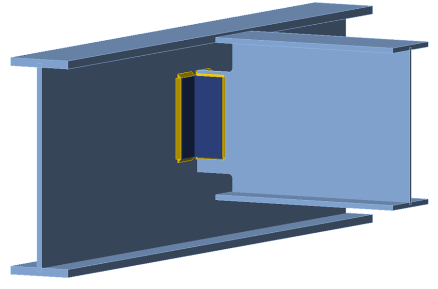
Figure 14 Vue tridimensionnelle de l'assemblage de poutre à extrémité réduite double
Les calculs ont été effectués sur 13 longueurs d'extrémité réduite différentes allant de 4 à 10 po par incréments de 1/2 po. La charge de cisaillement pondérée maximale pouvant être appliquée à l'assemblage (c'est-à-dire la résistance de l'assemblage) est présentée à la Figure 15. Comme prévu, tant pour les résultats des calculs traditionnels que pour les résultats d'IDEA StatiCa, la résistance de calcul diminue avec l'augmentation de la longueur de l'extrémité réduite. Pour les calculs traditionnels, la résistance de la soudure à l'appui était déterminante pour la longueur d'extrémité réduite initiale de 4 po, au-delà de laquelle le déversement de l'âme de la poutre gouvernait la résistance de calcul. Pour IDEA StatiCa, la limite de déformation plastique de 5 % de l'âme de la poutre gouvernait toutes les longueurs d'extrémité réduite jusqu'à 9-1/2 po, et la limite de rapport de flambement de 3,0 gouvernait pour la longueur d'extrémité réduite de 10 po. Comme pour les assemblages à extrémité réduite simple, la résistance obtenue avec IDEA StatiCa est inférieure ou égale à la résistance des calculs traditionnels sur la plage de longueurs étudiée.
La variation de la résistance de l'assemblage en fonction de la longueur de l'extrémité réduite obtenue avec IDEA StatiCa, présentée à la Figure 15, n'est pas régulière et dans certains cas la résistance augmente avec la longueur de l'extrémité réduite. Ce comportement inattendu pourrait être dû à des effets de maillage. En utilisant un maillage raffiné (16 éléments sur l'âme ou la semelle du plus grand élément), les résultats sont plus réguliers, mais pas sensiblement différents de ceux obtenus avec le maillage par défaut.
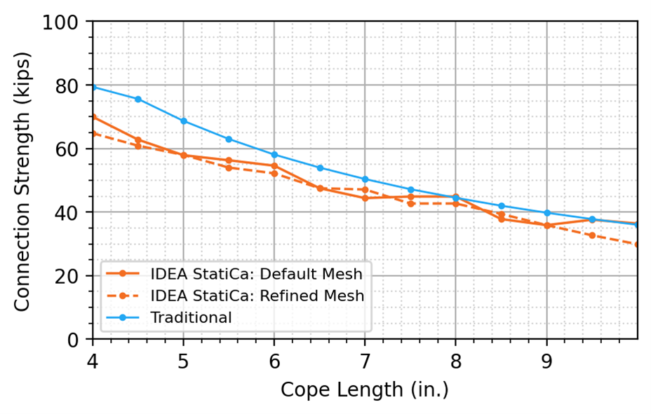
Figure 15 Résistance de l'assemblage en fonction de la longueur de l'extrémité réduite pour une poutre à extrémité réduite double
Flambement par cisaillement – Résistance en fonction de la profondeur de l'extrémité réduite
Pour étudier l'état limite de flambement par cisaillement, une poutre W18x35 a été modifiée pour avoir une hauteur de 24 po, présentant une âme plus élancée pour l'analyse. Une poutre principale W24x104 a été utilisée, avec la largeur de semelle modifiée pour s'adapter à une longueur d'extrémité réduite de poutre plus courte, et la double cornière L3-1/2x3x1/2 a été allongée à 14 po.
Des longueurs d'extrémité réduite de 1-1/2 po et 7-1/2 po ont été évaluées avec des profondeurs d'extrémité réduite variables pour identifier les configurations d'extrémité réduite où le flambement par cisaillement était déterminant pour les calculs traditionnels. Ces résultats ont été comparés aux résultats de l'analyse CBFEM d'IDEA StatiCa. La Figure 16 et la Figure 17 présentent des vues tridimensionnelles des assemblages avec des longueurs d'extrémité réduite de 1-1/2 po et 7-1/2 po, respectivement.
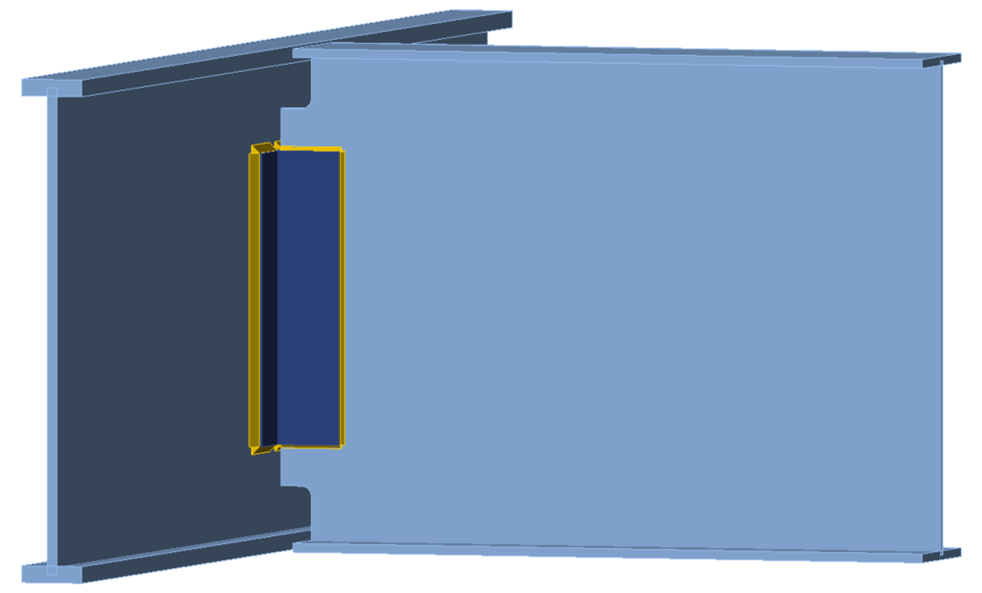
Figure 16 Vue tridimensionnelle de la poutre à extrémité réduite double avec une âme profonde (longueur d'extrémité réduite de 1,5 po)
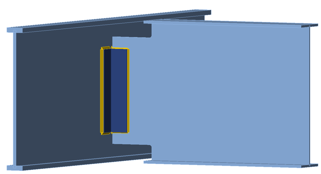
Figure 17 Vue tridimensionnelle de la poutre à extrémité réduite double avec une âme profonde (longueur d'extrémité réduite de 7,5 po)
Les calculs ont été effectués sur 8 profondeurs d'extrémité réduite différentes allant de 1 à 4,5 po par incréments de 1/2 po. La charge de cisaillement pondérée maximale pouvant être appliquée à l'assemblage est présentée à la Figure 18.
Pour les calculs traditionnels, l'état limite de flambement par cisaillement était déterminant pour toutes les profondeurs d'extrémité réduite pour la longueur d'extrémité réduite de 1-1/2 po. Pour la longueur d'extrémité réduite de 7-1/2 po, le flambement par cisaillement était déterminant pour des profondeurs d'extrémité réduite jusqu'à 2-1/2 po inclus, au-delà desquelles le déversement de l'âme de la poutre était déterminant. L'augmentation initiale de la résistance de l'assemblage associée à des extrémités réduites supérieure et inférieure plus profondes (c'est-à-dire moins de matière) est due à la réduction de l'élancement de la section à extrémité réduite, entraînant une augmentation du coefficient de résistance au flambement par cisaillement de l'âme, Cv2. Cependant, Cv2 reste inférieur à la limite supérieure de 1,0 où la plastification en cisaillement commencerait à être déterminante. Pour la longueur d'extrémité réduite plus grande de 7-1/2 po, le déversement commence à être déterminant au-delà de profondeurs d'extrémité réduite de 2-1/2 po, entraînant une réduction de la résistance de l'assemblage avec l'augmentation de la profondeur de l'extrémité réduite.
Pour IDEA StatiCa, la limite de rapport de flambement de 3,0 était déterminante pour toutes les profondeurs d'extrémité réduite pour les longueurs d'extrémité réduite de 1-1/2 po et 7-1/2 po. Pour la longueur d'extrémité réduite de 1-1/2 po, la résistance de l'assemblage reste constante, tandis que pour la longueur d'extrémité réduite de 7-1/2 po, la résistance de l'assemblage diminue avec l'augmentation de la profondeur de l'extrémité réduite. Cela s'explique par le fait que le flambement de l'âme de la poutre à extrémité réduite se produit entièrement en dehors de la section à extrémité réduite pour la longueur d'extrémité réduite de 1-1/2 po, tandis que pour la longueur d'extrémité réduite de 7-1/2 po, une partie du flambement se produit dans la section à extrémité réduite. La Figure 19 montre la forme déformée par flambement et les distributions de contraintes pour les deux cas. Elles sont cohérentes avec les représentations du flambement par cisaillement présentées par Dowswell (2018). La résistance de l'assemblage est inférieure pour IDEA StatiCa par rapport aux calculs traditionnels pour toute la plage de profondeurs d'extrémité réduite étudiée.
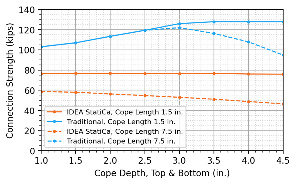
Figure 18 Résistance de l'assemblage en fonction de la profondeur de l'extrémité réduite pour une poutre à extrémité réduite double
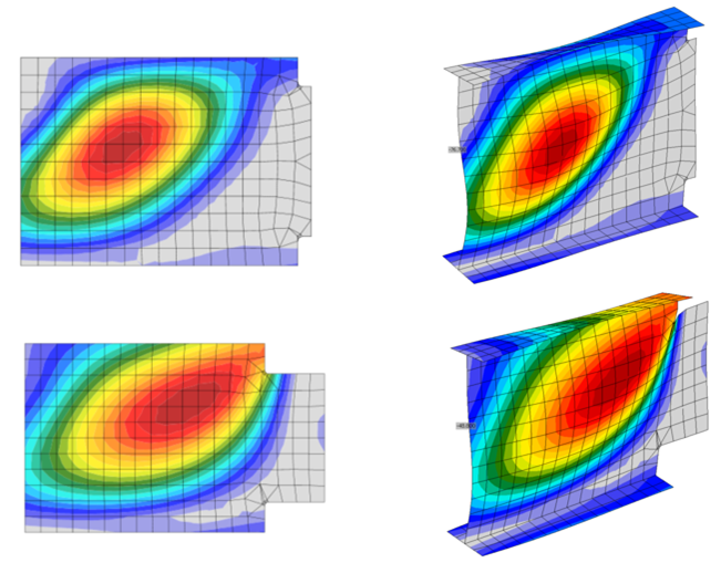
Figure 19 Forme déformée par flambement pour des longueurs d'extrémité réduite de 1-1/2 po et 7-1/2 po (profondeur d'extrémité réduite de 3-1/2 po)
Résumé
Cette étude a comparé le dimensionnement des extrémités réduites de poutres par les méthodes de calcul traditionnelles utilisées dans la pratique américaine et IDEA StatiCa. Les principales observations de l'étude comprennent :
- IDEA StatiCa s'est avéré conservateur par rapport aux calculs traditionnels pour les états limites associés aux extrémités réduites de poutres, en particulier les états limites de flambement. La limite de rapport de flambement utilisée dans cette étude était de 3,0.
- L'utilisation d'un rayon d'angle rentrant approprié (par ex., 3/8 à 1/2 po pour les assemblages à chargement statique comme indiqué dans la note d'utilisation de la Section M2.2 de la norme AISC Specification) et la modélisation du rayon d'angle tel que conçu dans IDEA StatiCa permettront d'éviter la génération d'éléments de maillage mal formés.
- La position de la force appliquée doit être fixée à la face de l'appui de l'âme pour être cohérente avec les hypothèses du Manuel AISC. Cependant, d'autres hypothèses peuvent être appropriées pour le dimensionnement.
Références
- AISC. (2016). Specification for Structural Steel Buildings. American Institute of Steel Construction, Chicago, Illinois.
- AISC. (2017). Steel Construction Manual, 15e édition. American Institute of Steel Construction, Chicago, Illinois.
- AISC (2019). Steel Construction Manual Design Examples, v15.1. American Institute of Steel Construction, Chicago, Illinois.
- Dowswell, B. (2018). « Designing Beam Copes. » Modern Steel Construction, AISC. (Février), 16-21.