Reinforced column with a bracket (EN)
1 Starting a new project
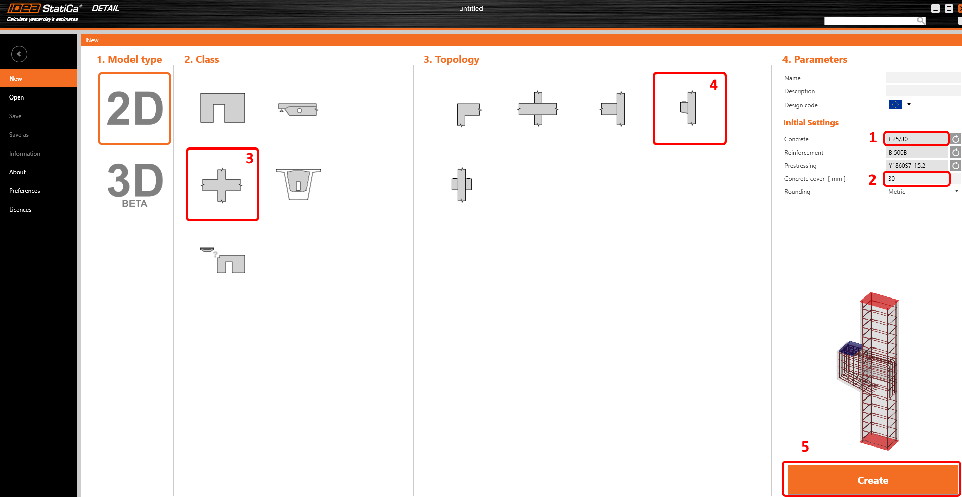
Let’s launch the IDEA StatiCa Detail application (download the newest version). In the main window of IDEA StatiCa, open the Detail application to define a new project.

In the first step, you define the design code (choose EN) as well as the concrete grade and cover (use concrete C25/30 and cover 30 mm). You can change your choice of material (or add another one) later, nevertheless, the design code can be chosen only in this first step of the project.
You can then find your desired detail shape among the templates. For the corbel design, select Frame joints class and Column with bracket topology. If you don't find a suitable template, you can start with a blank project.
2 Geometry
The Detail application will open with the Design tab automatically selected. You can set up your model by editing the items in the tree menu where you can modify members, transfer devices, loads and reinforcements. Alternatively you can define new items using commands in the top ribbon. If you want to get to know the application environment better, check out the following article - General interface in Detail application.
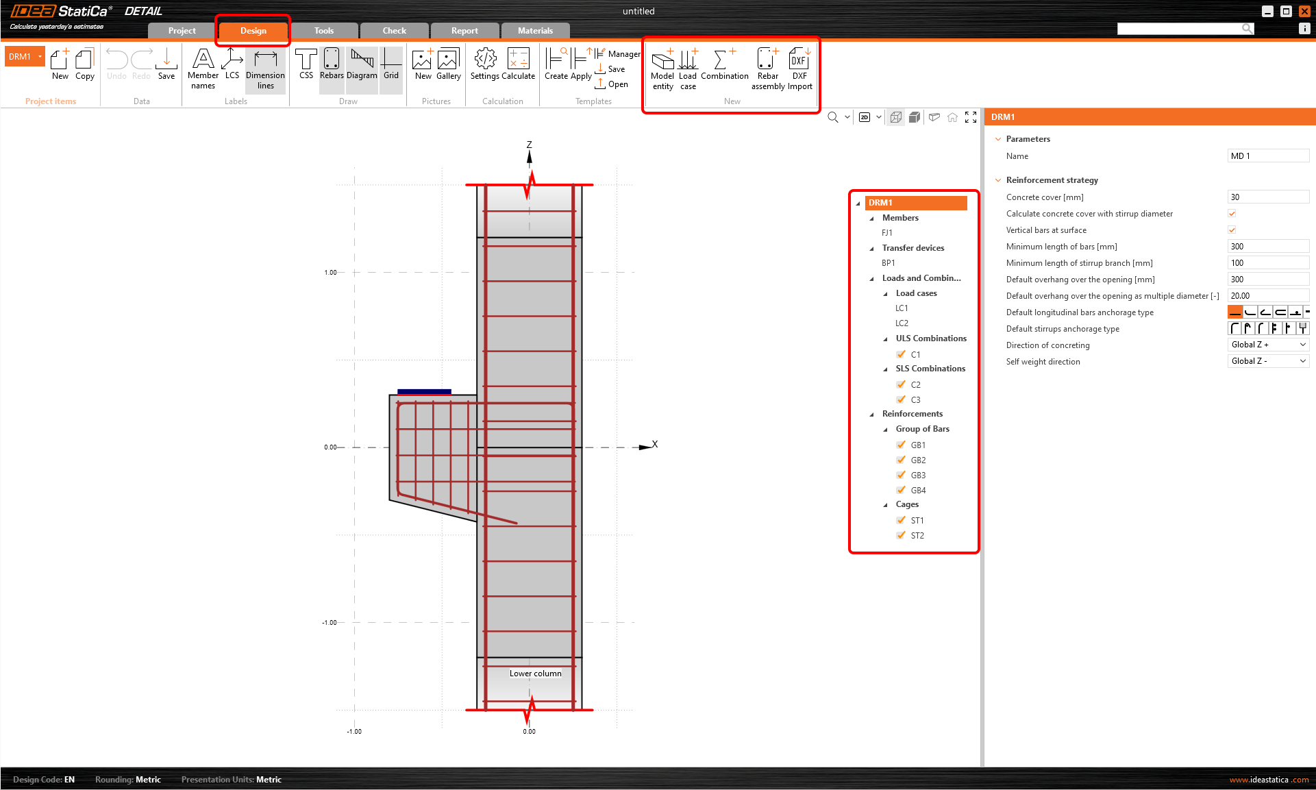
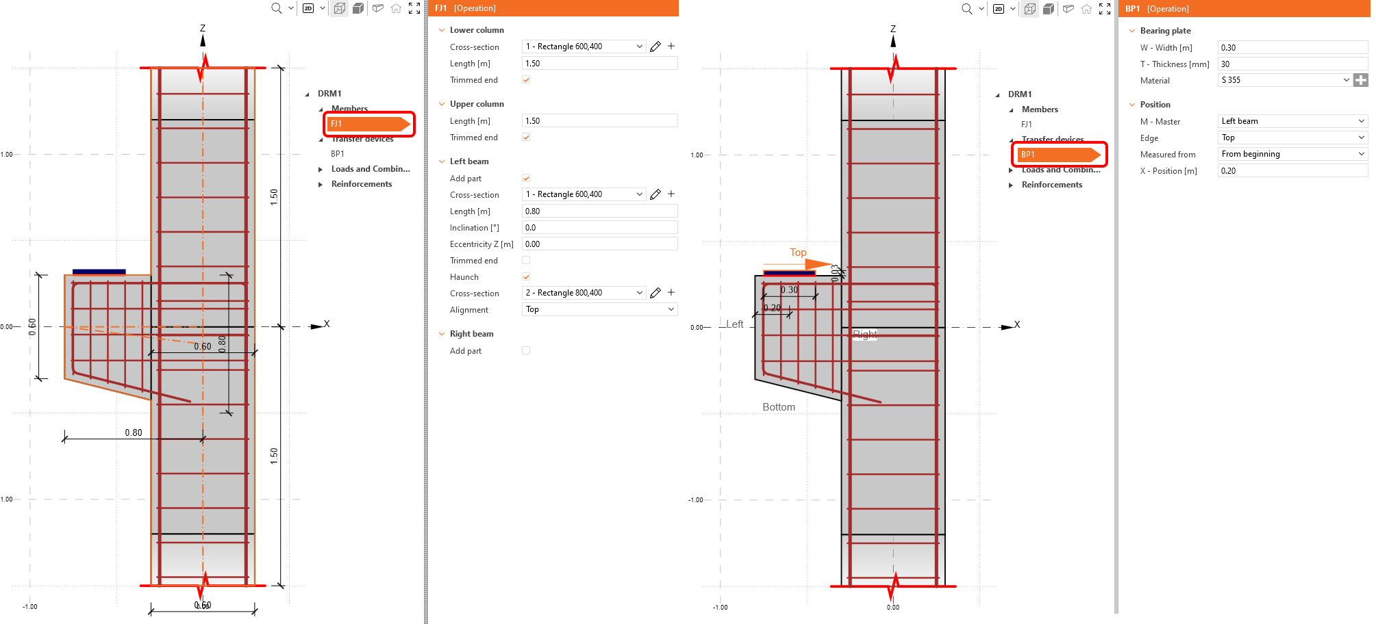
We will start with the Members and Transfer devices sections where you can adjust geometry items (walls, beams and openings), supports and load-transferring devices (such as bearing plate, patch support, etc.).
In this case, two items have already been created by the template: frame joint FJ1 and a bearing plate BP1.
- Read more about geometry types in Geometry Types in Detail
- Read more about supports in Types of supports in IDEA StatiCa Detail
3 Loads and Combinations
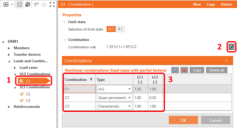
The third section belongs to the definition of Loads and Combinations. Two load cases (LC1 and LC2) and three combinations (C1, C2 and C3) were already automatically added.
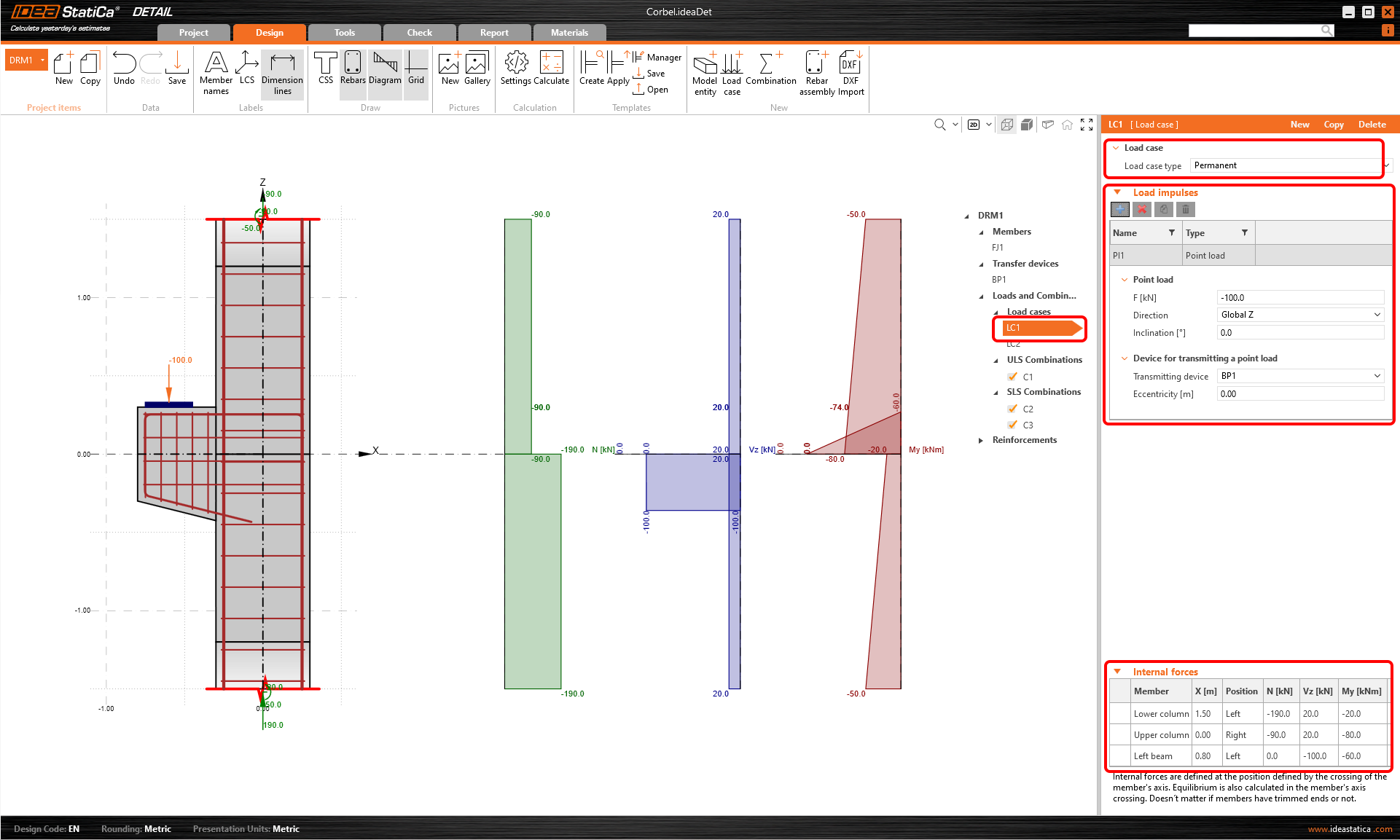
Let's start with the first load case. Click on LC1 in tree menu. In the property window on the right you can define everything relating to the load case.
First, you can specify the Load case type. In order to be able to distinguish between short-term and long-term effects, it is necessary to set correctly Permanent and Variable load case types. The settings greatly impacts the interpretation of ULS and SLS checks.
Then you can continue with the Load impulses where you can set external loads, such as point loads, line loads, surface loads and self weight.
The trimmed ends are used. That is why we need to set the Internal forces on individual members and reach equilibrium at the intersection of the column and the corbel.
You can set up the load case LC2 in a similar way. LC2 will represent the variable loads.
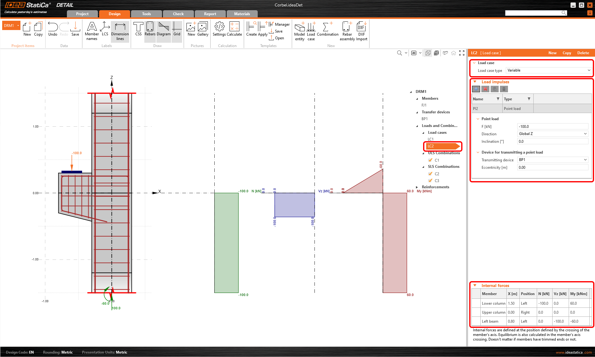
In the Main window, you can check if the internal forces correspond to the internal forces in the global model.
- Read more about Internal Forces and Equilibrium in Detail
- Read more about Load impulses in Detail
For each combination you can select the corresponding limit state, ULS or SLS. To modify the combination rules click on the pen icon and set the individual coefficients. Notice the ticked checkboxes for load combinations. The calculations will be performed just for the ticked items, and by excluding some of the combinations, you can speed up the calculation.
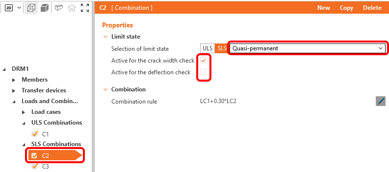
There are three types of SLS Combinations available: characteristic, frequent and quasi-permanent, and the user can select which SLS checks will be performed for each combination.
4 Reinforcement
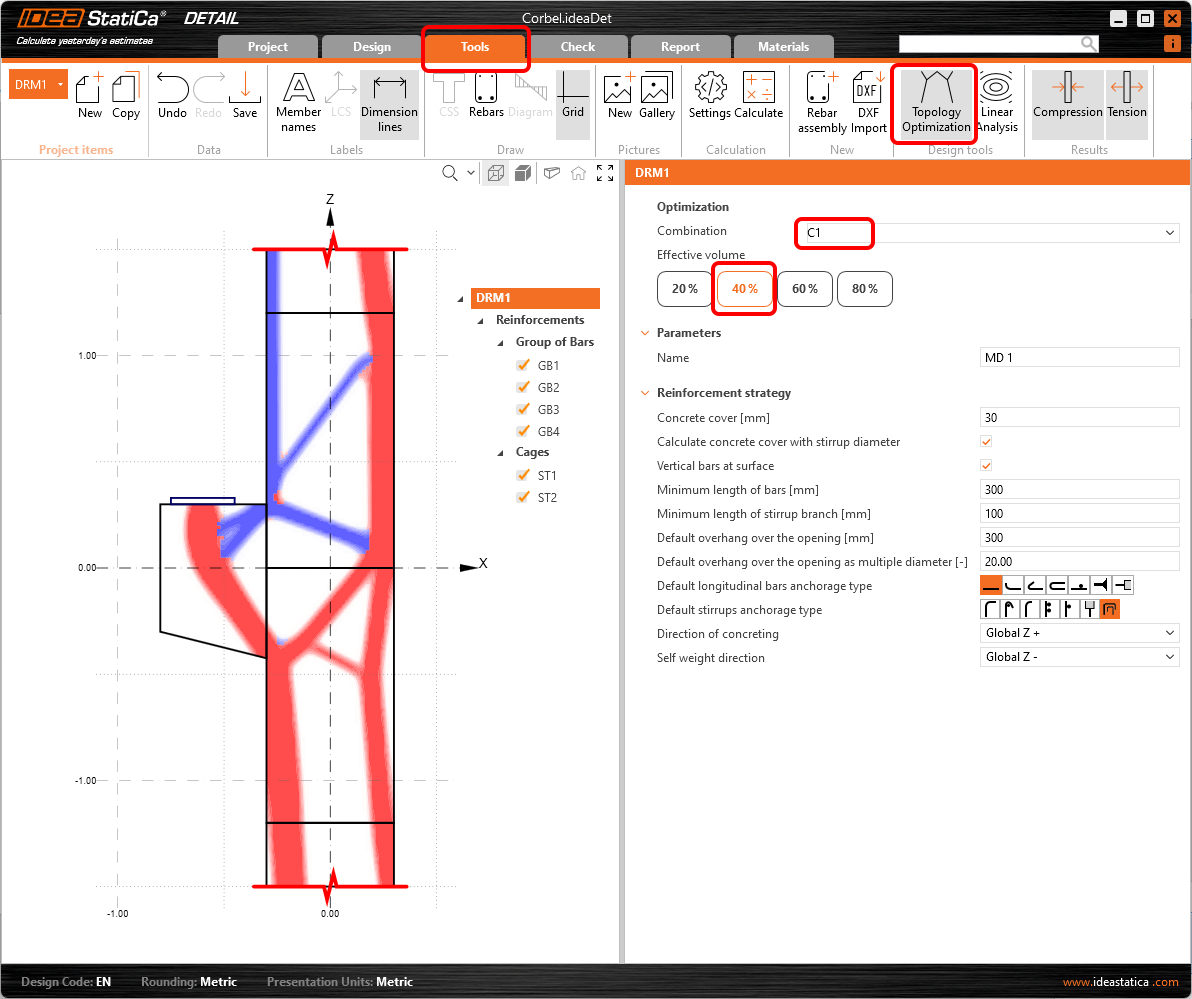
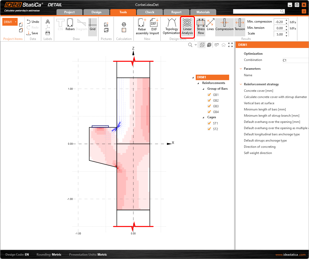
The next step is to reinforce the model. We will edit the Reinforcements from the template, but first, we can switch to the Tools tab and look at the Topology Optimization in Design tools that help you to design the reinforcement. Alternatively, you can use a more traditional Linear Analysis to get the hint for the reinforcement design.
- Read more about Topology Optimization
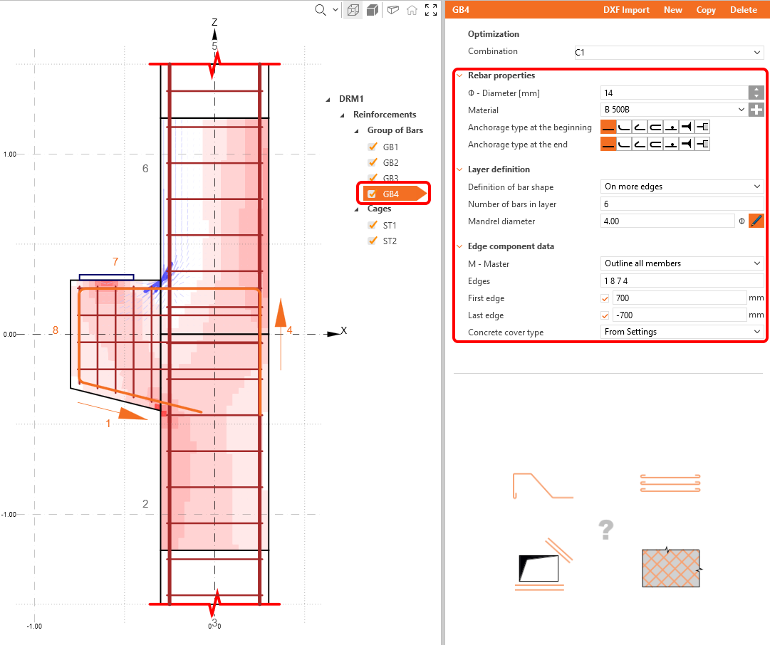
Now design the reinforcement. You can reinforce your detail based on the results from the Design tools. To do that just proceed to the Reinforcements in the tree menu.
Two stirrup groups and four groups of bars were already added by the template, you can adjust them to your needs in the property window.
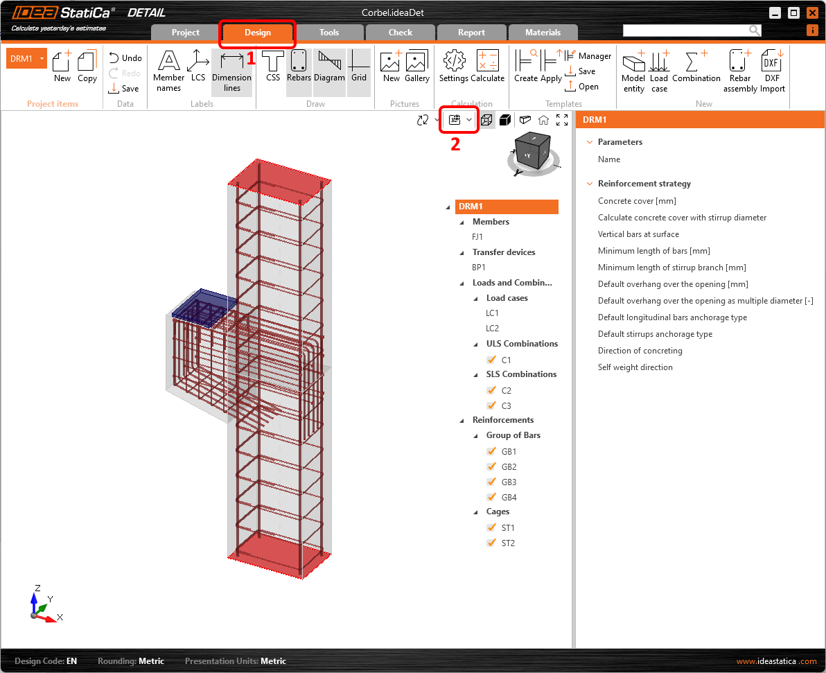
Lastly, check out the alignment of reinforcement visually using the Real 3D view. To do that you need to switch back to the Design tab first.
5 Calculation and Check
Navigate to Check and start the analysis by clicking on the Calculate button in the ribbon.
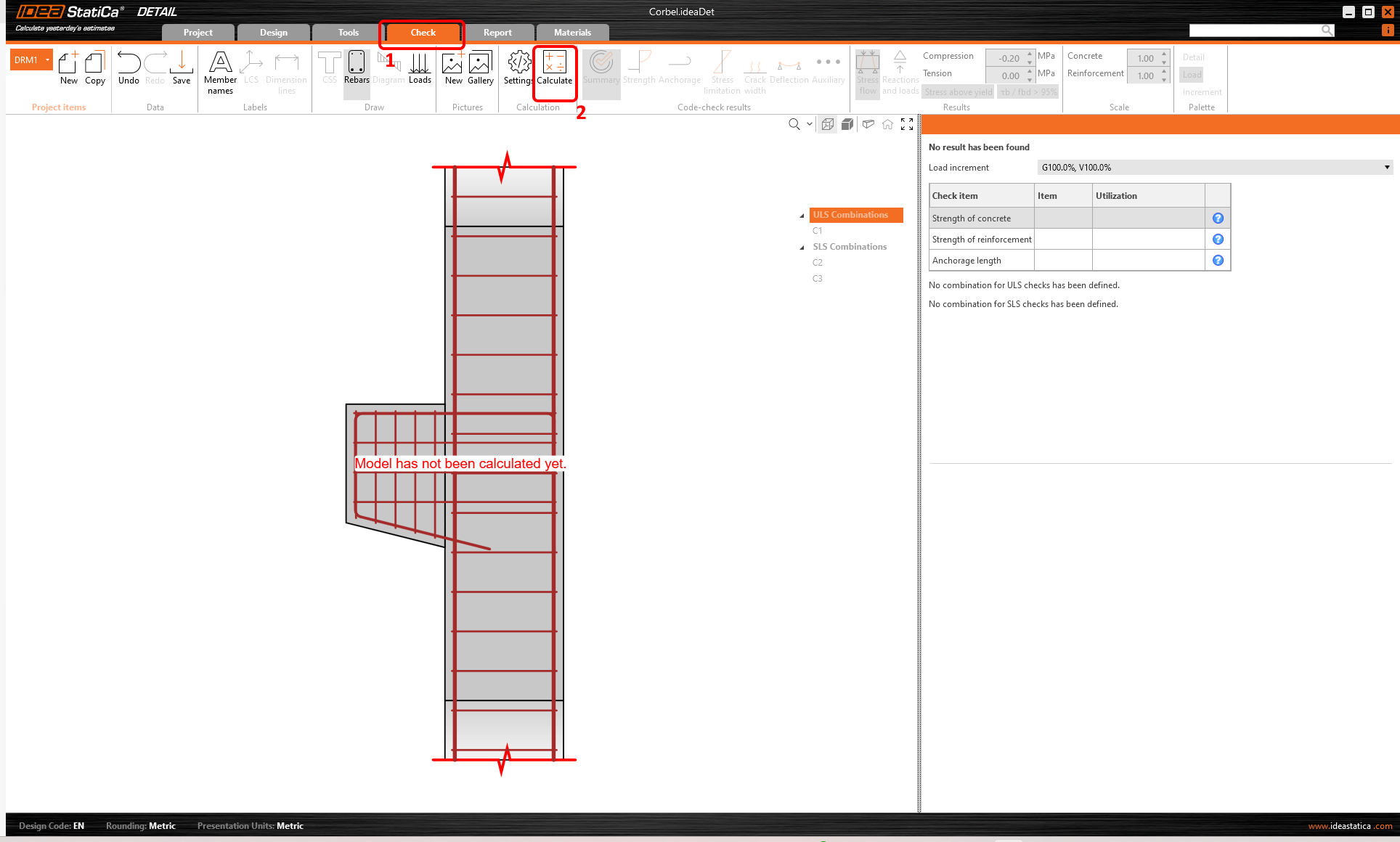
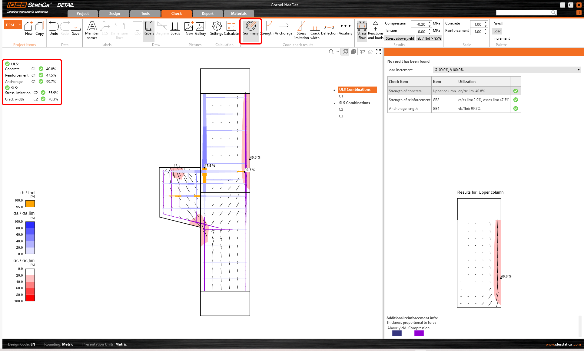
The analysis model is automatically generated. On the left, you can see the common results such as the utilization of the materials. The calculations are performed and you can see the Summary of checks displayed together with the values of check results.
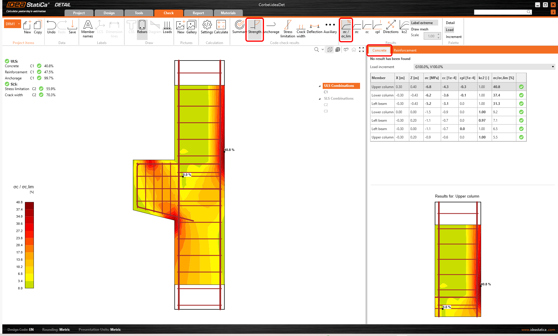
To go through the detailed checks of each component, start with the Strength. This will show concrete checks such as utilization in stress, the direction of principal stresses, strains, and also a map of reduction factor kc, which can be switched on in the ribbon. Also, you can change directions and scale of stress.
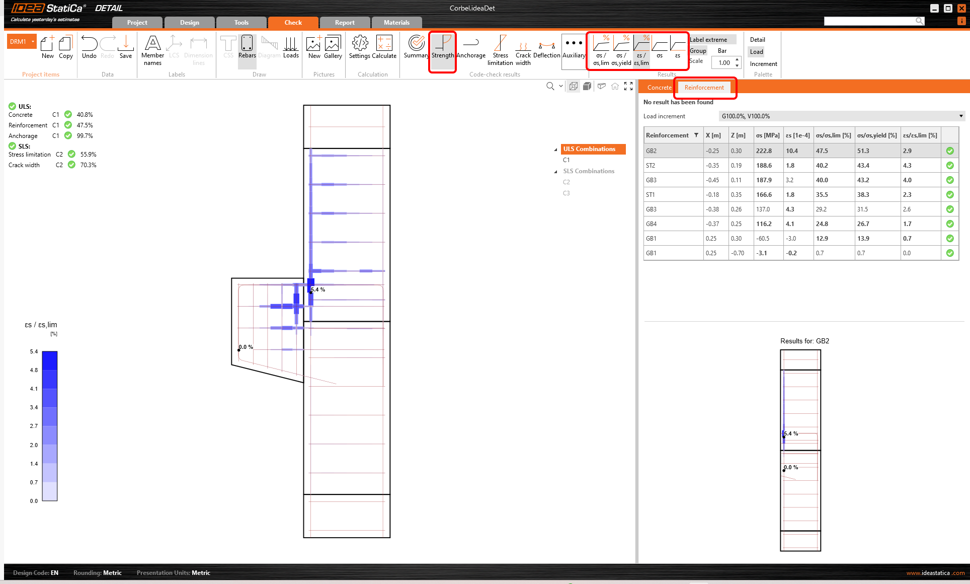
For detailed results of reinforcement, you need to switch to the Reinforcement tab. This will change the ribbon icons and also will unroll the table for results. You can display results for strains and stresses in each bar and their utilization.
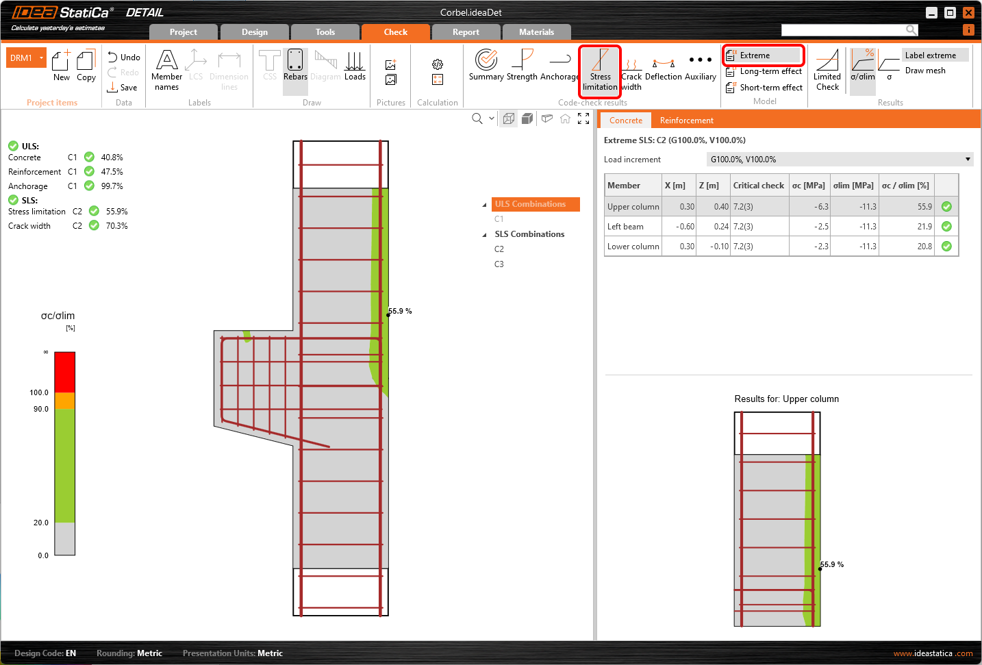
Let's go to the Stress limitation check. Besides the icons to switch between the results, there are settings in the ribbon to specify the limit value or display of results from short/long-term effects. Short-term effects are calculated considering elastic modulus Ecm. Long-term effects take into account the effect of creep of concrete, so the effective elastic modulus Ec,eff is taken into account.
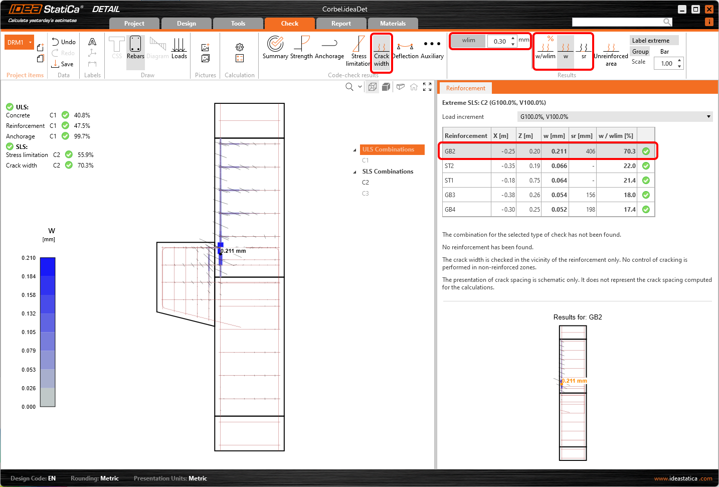
In the same way, you can also display SLS checks for Cracks and other results.
6 Printing report
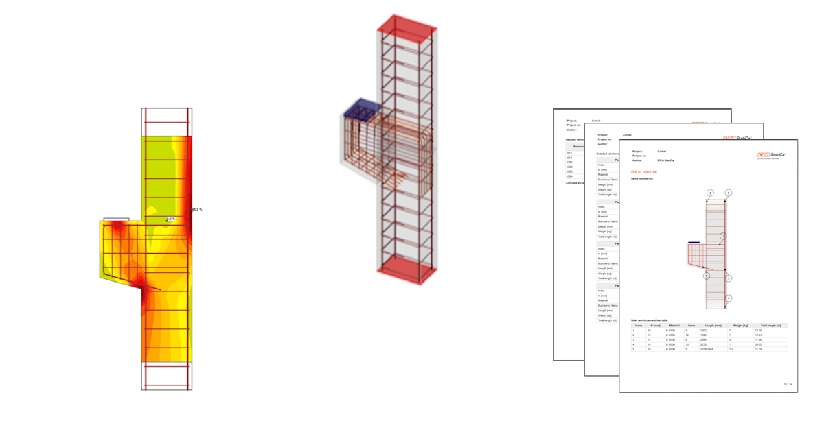
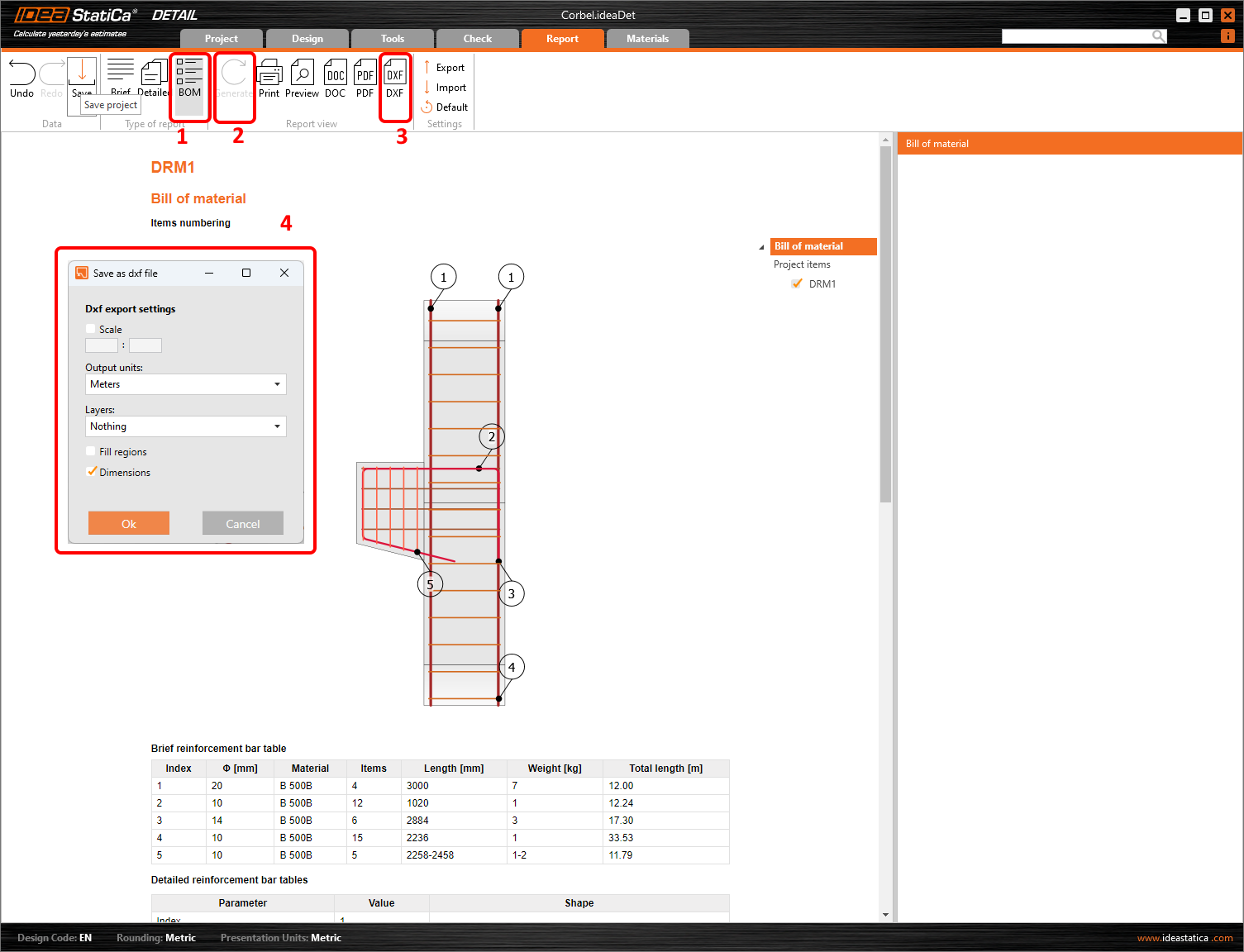
You can Generate the Bill of Material and click Export to DXF to generate the 2D drawings. All the reinforcement is exported into blocks that can be exploded into polylines.
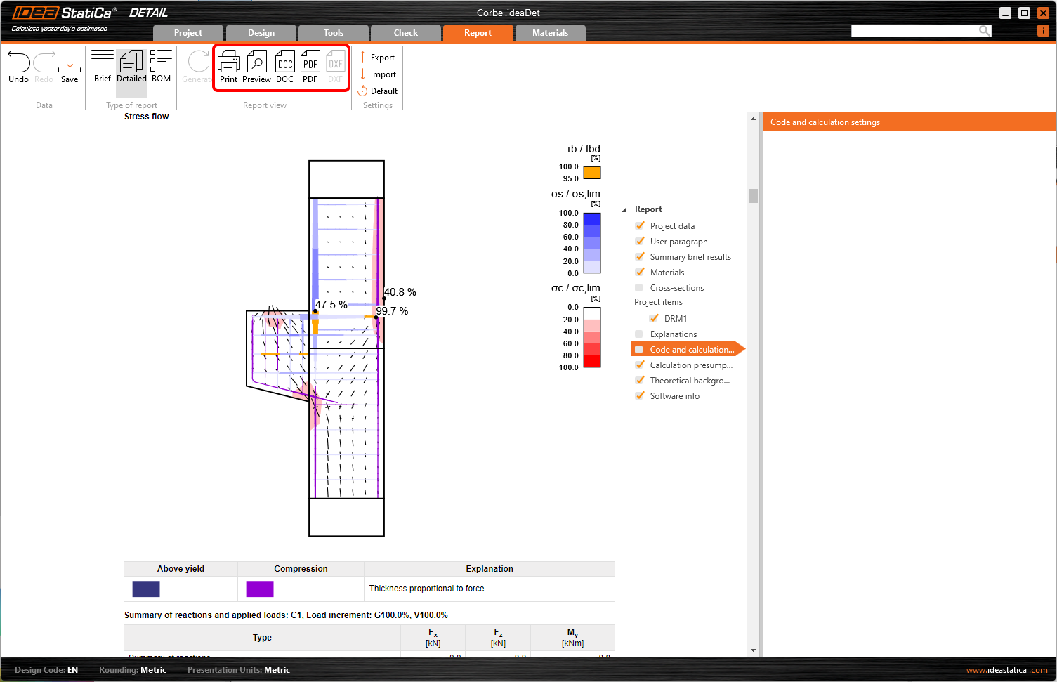
Now it is time to print a report of your calculations. Go to the Report tab. You can choose Brief or Detailed type of report and further adjust the report based on your needs in the tree menu. Select the preferred options and press Generate in the top ribbon.
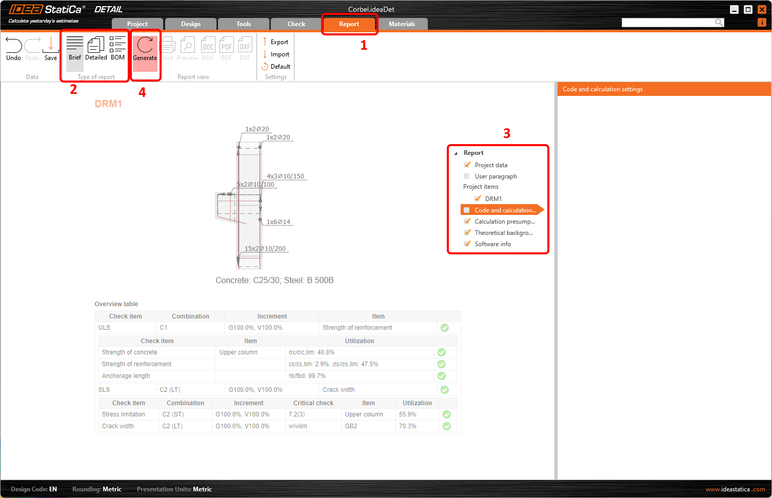
The report is generated and we can print it into PDF or export to a Microsoft Word file.
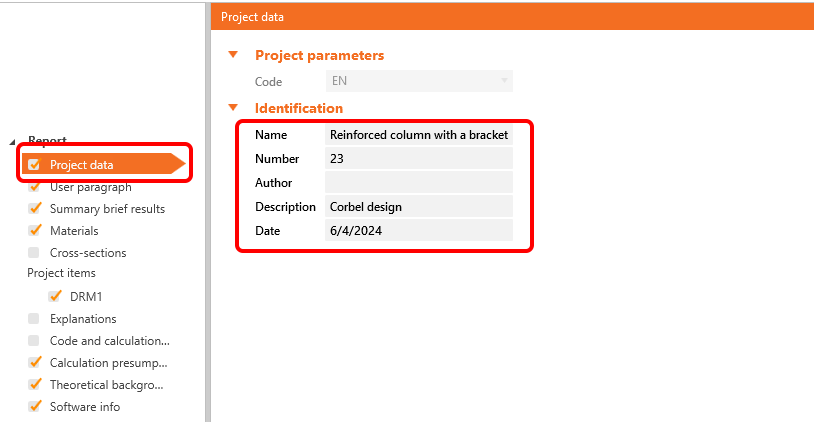
To change the header of the report, go to the Project data.
Don't forget to Save your project and we are done!
You can continue learning IDEA StatiCa with many more tutorials in our Support center.