Vérification normative des ancrages selon les normes canadiennes
Les forces dans les ancrages, y compris les efforts de levier, sont déterminées par analyse par éléments finis, mais les résistances sont vérifiées selon les dispositions normatives de la norme A23.3 - Annexe D.
Les tiges d'ancrage sont dimensionnées conformément à la norme A23.3-14 – Annexe D. Les résistances suivantes des boulons d'ancrage sont évaluées :
- Résistance de l'acier de l'ancrage en traction Nsar,
- Résistance à l'arrachement du cône de béton en traction Ncbr,
- Résistance à l'extraction du béton Npr,
- Résistance à l'éclatement latéral du béton Nsbr,
- Résistance de l'acier de l'ancrage en cisaillement Vsar,
- Résistance à l'arrachement du cône de béton en cisaillement Vcbr,
- Résistance au soulèvement du béton de l'ancrage en cisaillement Vcpr.
L'état du béton peut être choisi par l'utilisateur comme fissuré ou non fissuré. Le type d'ancrages (ancrages coulés en place à tête avec rondelles circulaires ou rectangulaires, ancrages droits) est sélectionné par l'utilisateur ; la résistance à l'extraction et la résistance à l'éclatement latéral ne sont vérifiées dans le logiciel que pour les ancrages à tête.
Les vérifications suivantes des ancrages sollicités en traction ne sont pas effectuées et doivent être vérifiées à l'aide des informations figurant dans la Spécification Technique de Produit pertinente (basée sur le fractile à 5 % des essais) :
- Rupture par extraction de l'élément de fixation (pour les ancrages post-installés mécaniques) – CSA A23.3-14 : D.6.3,
- Résistance d'adhérence de l'ancrage collé (pour les ancrages post-installés collés) – CSA A23.3-14 : D.6.5.
Les ancrages doivent satisfaire aux distances aux bords, espacements et épaisseurs requis pour éviter la rupture par fendage, conformément à la norme CSA A23.3-14 : D.9.
Résistance de l'acier de l'ancrage en traction
La résistance de l'acier de l'ancrage en traction est déterminée conformément à la norme CSA A23.3-14 – D.6.1 comme suit :
Nsar = Ase,N ϕs futa R
où :
- ϕs = 0,85 – facteur de résistance du matériau d'encastrement en acier pour le ferraillage
- Ase,N – aire de la section transversale efficace d'un ancrage en traction
- futa ≤ min (860 MPa, 1,9 fya) – résistance à la traction spécifiée de l'acier d'ancrage
- fya – limite d'élasticité spécifiée de l'acier d'ancrage
- R = 0,8 – facteur de modification de la résistance tel que spécifié dans la norme CSA A23.3.-14 – D.5.3
Résistance à l'arrachement du cône de béton de l'ancrage en traction
La résistance à l'arrachement du cône de béton est dimensionnée selon la méthode Concrete Capacity Design (CCD) de la norme CSA A23.3-14 – D.6.2. Dans la méthode CCD, le cône de béton est considéré comme se formant à un angle d'environ 34° (pente de 1 vertical pour 1,5 horizontal). Par simplification, le cône est considéré comme carré plutôt que circulaire en plan. La contrainte d'arrachement du béton dans la méthode CCD est considérée comme diminuant avec l'augmentation de la taille de la surface d'arrachement.
\[ N_{cbrg} = \frac{A_{Nc}}{A_{Nco}} \psi_{ed,N} \psi_{ec,N} \psi_{c,N} N_{br} \]
où :
- ANc – aire du cône d'arrachement du béton pour un groupe d'ancrages sollicités en traction formant un cône de béton commun
- ANco = 9 hef2 – aire du cône d'arrachement du béton pour un ancrage isolé non influencé par les bords du béton
- \( \psi_{ed,N} = \min \left ( 0.7+\frac{0.3 c_{a,min}}{1.5 h_{ef}}, \, 1 \right ) \) – facteur de modification pour la distance aux bords
- ca,min – la plus petite distance de l'ancrage au bord
- hef – profondeur d'encastrement ; conformément à la norme A23.3-14 – D.6.2.3, la profondeur d'encastrement efficace hef est réduite à \( h_{ef} = \max \left ( \frac{c_{a,max}}{1.5}, \, \frac{s}{3} \right ) \) si les ancrages sont situés à moins de 1,5 hef de trois bords ou plus
- \( \psi_{ec,N} = \frac{1}{1+\frac{2e'_N}{3 h_{ef}}} \) – facteur de modification pour un groupe d'ancrages chargé de manière excentrique
- e'N – excentricité de la charge de traction par rapport au centre de gravité des ancrages sollicités en traction formant un cône de béton commun
- Ψc,N – facteur de modification pour les conditions du béton ; Ψc,N = 1 pour le béton fissuré, Ψc,N = 1,25 pour le béton non fissuré
- \( N_{br} = k_c \phi_c \lambda_a \sqrt{f'_c} h_{ef}^{1.5} R \) – résistance de base à l'arrachement du cône de béton d'un ancrage isolé en traction dans le béton fissuré ; pour les ancrages à tête coulés en place et 275 mm ≤ hef ≤ 625 mm, \( N_{br} = 3.9 \phi_c \lambda_a \sqrt{f'_c} h_{ef}^{5/3} R \)
- ϕc=0,65 – facteur de résistance du béton
- kc=10 pour les ancrages coulés en place
- s – espacement entre les ancrages
- ca,max – distance maximale d'un ancrage à l'un des trois bords proches
- λa = 1 – facteur de modification pour le béton léger
- f'c – résistance à la compression du béton [MPa]
- R = 1 – facteur de modification de la résistance tel que spécifié dans la norme CSA A23.3 – D.5.3
Conformément à la norme A23.3-14 – D.6.2.8, dans le cas d'ancrages à tête, l'aire de surface projetée ANc est déterminée à partir du périmètre efficace de la rondelle, qui est la valeur la plus faible entre da + 2 twp et dwp, où :
- da – diamètre de l'ancrage
- dwp – diamètre ou dimension du côté de la rondelle
- twp – épaisseur de la rondelle
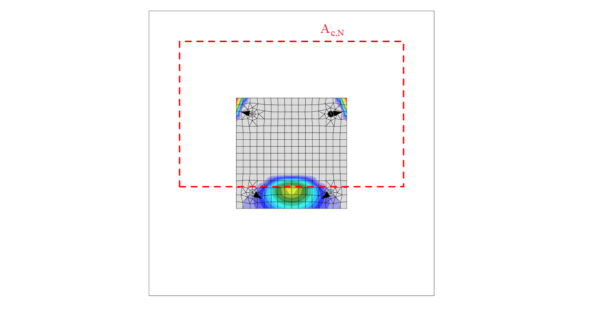
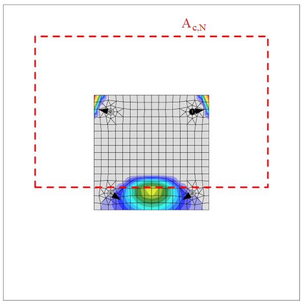
Le groupe d'ancrages est vérifié par rapport à la somme des efforts de traction dans les ancrages sollicités en traction formant un cône de béton commun.
L'aire du cône d'arrachement du béton pour le groupe d'ancrages sollicités en traction formant un cône de béton commun, Ac,N, est représentée par un trait pointillé rouge.
Conformément à la norme CSA A23.3-14 – D.6.2.9, lorsque le ferraillage d'ancrage est ancré conformément à la clause 12 de la norme A23.3-14 des deux côtés de la surface d'arrachement, il est supposé que le ferraillage d'ancrage reprend les efforts de traction, et la résistance à l'arrachement du cône de béton n'est pas évaluée (peut être défini dans la configuration normative).
Résistance à l'extraction du béton de l'ancrage en traction
La résistance à l'extraction du béton d'un ancrage à tête est définie dans la norme CSA A23.3-14 – D.6.3 comme suit :
Ncpr = Ψc,P Npr
où :
- Ψc,P – facteur de modification pour les conditions du béton ; Ψc,P = 1,0 pour le béton fissuré, Ψc,P = 1,4 pour le béton non fissuré
- Npr = 8 Abrg ϕc f'c R pour un ancrage à tête
- Abrg – aire d'appui de la tête du goujon à tête ou du boulon d'ancrage
- ϕc = 0,65 – facteur de résistance du béton
- da – diamètre de l'ancrage
- f'c – résistance à la compression du béton
- R = 1 – facteur de modification de la résistance tel que spécifié dans la norme CSA A23.3 – D.5.3
La résistance à l'extraction du béton pour les types d'ancrages autres qu'à tête n'est pas évaluée dans le logiciel et doit être spécifiée par le fabricant.
Résistance à l'éclatement latéral du béton
La résistance à l'éclatement latéral du béton d'un ancrage à tête en traction est définie dans la norme CSA A23.3-14 – D.6.4 comme suit :
\[ N_{sbr} = 13.3 c_{a1} \sqrt{A_{brg}} \phi_c \lambda_a \sqrt{f'_c} R \]
Si ca2 pour l'ancrage isolé sollicité en traction est inférieur à 3 ca1, la valeur de Nsbr est multipliée par le facteur 0,5 ≤ (1+ ca2 / ca1) / 4 ≤ 1.
D.6.4.2 exige qu'un groupe d'ancrages à tête avec un encastrement profond proche d'un bord (hef > 2,5 ca1) et un espacement entre ancrages inférieur à 6 ca1 ait la résistance suivante :
\[ N_{sbgr} = \left (1 + \frac{s} {6 c_{a1}} \right ) N_{sbr} \]
Un seul facteur de réduction est appliqué à la fois.
IDEA StatiCa vérifie toujours chaque ancrage indépendamment pour la résistance à l'éclatement latéral et, par conséquent, aucun groupe de deux ancrages n'est supposé ; le facteur de réduction est plutôt divisé par deux. Cela donne le même résultat si les efforts de traction dans chaque ancrage sont identiques, et constitue une hypothèse conservative si les efforts diffèrent. Le facteur de réduction utilisé dans IDEA StatiCa est :
\[ r_c = \min \left \{ \frac{1+\frac{c_{a2}}{c_{a1}}}{4}, \frac{1+\frac{s}{6\cdot c_{a1}}}{2} \right \} \]
\[0.5 \le r_c \le 1.0\]
où :
- ca1 – la plus courte distance d'un ancrage à un bord
- ca2 – la plus grande distance, perpendiculaire à ca1, d'un ancrage à un bord
- Abrg – aire d'appui de la tête du goujon à tête ou du boulon d'ancrage
- ϕc – facteur de résistance du béton modifiable dans la configuration normative
- f'c – résistance à la compression du béton
- hef – profondeur d'encastrement ; conformément à la norme A23.3-14 – D.6.2.3, la profondeur d'encastrement efficace hef est réduite à \( h_{ef} = \max \left ( \frac{c_{a,max}}{1.5}, \, \frac{s}{3} \right ) \) si les ancrages sont situés à moins de 1,5 hef de trois bords ou plus
- s – espacement entre les ancrages
- R = 1 – facteur de modification de la résistance tel que spécifié dans la norme CSA A23.3 – D.5.3
Résistance de l'acier de l'ancrage en cisaillement
La résistance de l'acier en cisaillement est déterminée conformément à la norme A23.3 – D.7.1 comme suit :
Vsar = Ase,V ϕs 0,6 futa R
où :
- ϕs = 0,85 – facteur de résistance du matériau d'encastrement en acier pour le ferraillage
- Ase,V – aire de la section transversale efficace d'un ancrage en cisaillement
- futa – résistance à la traction spécifiée de l'acier d'ancrage, sans dépasser la plus petite valeur entre 1,9 fya et 860 MPa
- R = 0,75 – facteur de modification de la résistance tel que spécifié dans la norme CSA A23.3 – D.5.3
Si un joint de mortier est sélectionné, la résistance de l'acier en cisaillement Vsa est multipliée par 0,8 (A23.3 – D.7.1.3).
Le cisaillement sur bras de levier, présent dans le cas d'une platine de base avec trous surdimensionnés et rondelles ou plaques ajoutées sur le dessus de la platine de base pour transmettre l'effort de cisaillement, n'est pas pris en compte.
Résistance à l'arrachement du cône de béton de l'ancrage en cisaillement
La résistance à l'arrachement du cône de béton d'un ancrage en cisaillement est dimensionnée conformément à la norme A23.3 – D.7.2. L'effort de cisaillement agissant sur une platine de base est supposé être repris par les ancrages les plus proches du bord dans la direction de l'effort de cisaillement. La direction de l'effort de cisaillement par rapport au bord du béton affecte la résistance à l'arrachement du cône de béton conformément au Bulletin FIB 58 – Design of anchorages in concrete – Guide to good practice (2011). Si les cônes de béton des ancrages se chevauchent, ils forment un cône de béton commun. L'excentricité en cisaillement est également prise en compte.
\[ V_{cbr} = \frac{A_{Vc}}{A_{Vco}} \psi_{ec,V} \psi_{ed,V} \psi_{c,V} \psi_{h,V} \psi_{\alpha,V} V_{br} \]
où :
- AVc – aire de rupture du béton projetée d'un ancrage ou d'un groupe d'ancrages divisée par le nombre d'ancrages dans ce groupe
- AVco = 4,5 ca12 – aire de rupture du béton projetée d'un ancrage isolé sans influence de coin, d'espacement ou d'épaisseur de l'élément
- \( \psi_{ec,V} = \frac{1}{1+ \frac{2 e'_V}{3c_{a1}}} \) – facteur de modification pour un groupe d'ancrages chargé de manière excentrique en cisaillement
- \( \psi_{ed,V} = 0.7 + 0.3 \frac{c_{a2}}{1.5 c_{a1}}\le1.0 \) – facteur de modification pour l'effet de bord
- Ψc,V – facteur de modification pour les conditions du béton ; Ψc,V = 1,0 pour le béton fissuré, Ψc,V = 1,4 pour le béton non fissuré
- \( \psi_{h,V}=\sqrt{\frac{1.5c_{a1}}{h_a}} \ge 1 \) – facteur de modification pour les ancrages situés dans un élément en béton où ha < 1,5 ca1
- \( \psi_{\alpha,V} = \sqrt{\frac{1}{(\cos \alpha_V)^2+(0.5\sin \alpha_V)^2}} \) – facteur de modification pour les ancrages chargés à un angle par rapport au bord du béton (Bulletin FIB 58 – Design of anchorages in concrete – Guide to good practice, 2011)
- ha – hauteur de la surface de rupture côté béton
- \( V_{br}=\min \left(0.58 \left (\frac{l_e}{d_a} \right )^{0.2} \sqrt{d_a} \phi_c \lambda_a \sqrt{f'_c} c_{a1}^{1.5} R, \, 3.75 \lambda_a \phi_c \sqrt{f'_c} c_{a1}^{1.5} R \right ) \)
- le = hef ≤ 8 da – longueur portante de l'ancrage en cisaillement
- da – diamètre de l'ancrage
- f'c – résistance à la compression du béton
- ca1 – distance au bord dans la direction de la charge ; conformément à l'article 17.5.2.4, pour un élément étroit, c2,max < 1,5 c1 également considéré comme mince, ha < 1,5 c1, c'1 est utilisé dans les équations précédentes à la place de c1 ; la valeur réduite c'1 = max (c2,max / 1,5, ha / 1,5, sc,max / 3)
- ca2 – distance au bord dans la direction perpendiculaire à la charge
- c2,max – plus grande distance au bord dans la direction perpendiculaire à la charge
- sc,max – espacement maximal perpendiculaire à la direction du cisaillement, entre les ancrages d'un groupe
- ϕc = 0,65 – facteur de résistance du béton
- R = 1 – facteur de modification de la résistance tel que spécifié dans la norme CSA A23.3 – D.5.3
Si les deux distances au bord ca2 ≤ 1,5ca1 et ha ≤ 1,5 ca1, \( c_{a1} = \max \left ( \frac{c_{a2}}{1.5}, \, \frac{h_a}{1.5}, \, \frac{s}{3} \right ) \), où s est l'espacement maximal perpendiculaire à la direction du cisaillement, entre les ancrages d'un groupe.
Conformément à la norme A23.3-14 – D.7.2.9, lorsque le ferraillage d'ancrage est ancré conformément à la norme A23.3-14 – Clause 12 des deux côtés de la surface d'arrachement, il est supposé que le ferraillage d'ancrage reprend les efforts de cisaillement et la résistance à l'arrachement du cône de béton n'est pas évaluée.
Résistance au soulèvement du béton de l'ancrage en cisaillement
La résistance au soulèvement du béton est dimensionnée conformément à la norme A23.3 – D.7.3.
Vcpr = kcp Ncpr
où :
- kcp = 1,0 pour hef < 65 mm, kcp = 2,0 pour hef ≥ 65 mm
- Ncpr – résistance à l'arrachement du cône de béton – tous les ancrages sont considérés comme sollicités en traction
Conformément à la norme CSA A23.3-14 – D.6.2.9, lorsque le ferraillage d'ancrage est ancré conformément à la clause 12 de la norme A23.3-14 des deux côtés de la surface d'arrachement, il est supposé que le ferraillage d'ancrage reprend les efforts de traction et la résistance à l'arrachement du cône de béton n'est pas évaluée (peut être défini dans la configuration normative).
Interaction des efforts de traction et de cisaillement
L'interaction des efforts de traction et de cisaillement est évaluée conformément à la norme A23.3 – Figure D.18.
\[ \left ( \frac{N_f}{N_r} \right )^{5/3}+\left ( \frac{V_f}{V_r} \right )^{5/3} \le 1.0 \]
où :
- Nf et Vf – efforts de calcul agissant sur un ancrage
- Nr et Vr – les résistances de calcul les plus faibles déterminées à partir de tous les modes de rupture appropriés
Ancrages avec tige libre
L'ancrage avec tige libre est dimensionné comme un élément barre sollicité par un effort de cisaillement, un moment fléchissant et un effort de compression ou de traction. Ces efforts internes sont déterminés par le modèle par éléments finis. L'ancrage est encastré des deux côtés, un côté se trouve à 0,5×d en dessous du niveau du béton, l'autre côté se trouve au milieu de l'épaisseur de la plaque. La longueur de flambement est prise de manière conservative comme étant égale à deux fois la longueur de l'élément barre. Le module de résistance plastique est utilisé. L'élément barre est dimensionné conformément à la norme S16-14. L'interaction de l'effort de cisaillement est négligée car la longueur minimale de l'ancrage pour loger l'écrou sous la platine de base garantit que l'ancrage rompt en flexion avant que l'effort de cisaillement n'atteigne la moitié de la résistance au cisaillement, et l'interaction en cisaillement est négligeable (jusqu'à 7 %). L'interaction du moment fléchissant et de l'effort de compression ou de traction est prise de manière conservative comme linéaire. Les effets du second ordre ne sont pas pris en compte.
Résistance au cisaillement (CSA S16-14 – 13.4.4) :
Vr = ϕ ∙ 0,66 ∙ Av ∙ Fy
- Av = 0,844 ∙ As – l'aire de cisaillement
- As – l'aire du boulon réduite par les filets
- Fy – limite d'élasticité du boulon
- ϕ – le facteur de résistance, la valeur recommandée est 0,9
Résistance en traction (CSA S16-14 – 13.2)
Tr = ϕ ∙ As ∙ Fy
Résistance en compression (CSA S16-14 – 13.3.1)
\[ C_r = \frac{\phi A_s F_y}{\left (1+\lambda^{2n}\right )^{\frac{1}{n}}} \]
- \( \lambda = \sqrt{\frac{F_y}{F_e}} \) – élancement du boulon d'ancrage
- \( F_e = \frac{\pi^2 E}{\left (\frac{KL}{r}\right )^2} \) – contrainte de flambement élastique
- KL = 2 ∙ l – longueur de flambement
- l – longueur de l'élément boulon égale à la moitié de l'épaisseur de la platine de base + jeu + la moitié du diamètre du boulon
- \( r = \sqrt{\frac{I}{A_s}} \) – rayon de giration du boulon d'ancrage
- \( I=\frac{\pi d_s^4}{64} \) – moment d'inertie du boulon
- n = 1,34 – paramètre de résistance en compression
Résistance en flexion (CSA S16-14 – 13.5) :
Mr = ϕ ∙ Z ∙ Fy
Z = ds3 / 6 – module de résistance plastique du boulon
Interaction linéaire :
\( \frac{N}{C_r}+\frac{M}{M_r} \le 1 \) ... pour un effort normal de compression
\( \frac{N}{T_r}+\frac{M}{M_r} \le 1 \) ... pour un effort normal de traction
- N – effort de calcul de traction (signe positif) ou de compression (signe négatif)
- Cr – résistance de calcul en compression (signe négatif)
- Tr – résistance de calcul en traction (signe positif)
- M – moment fléchissant de calcul
- Mr – résistance de calcul au moment fléchissant
Dispositions constructives
L'espacement entre les ancrages doit être supérieur à quatre fois le diamètre de l'ancrage conformément à la norme A23.3-14 – D.9.2.
Les distances au bord par rapport à la platine acier suivent les règles des boulons, c'est-à-dire conformément à la norme S16-14 – 22.3. La distance minimale au bord (1,25 d – modifiable dans la configuration normative) est vérifiée.