Ancrage
Sous-code : LRFD
Type d'assemblage : Ancrage
Système d'unités : Métrique
Conçu conformément à : ACI 318-14
Étudié : Ancrages soumis à la traction et au cisaillement à proximité d'un bord
Matériau de la platine : A709, Gr. 50
Boulons : M12 A325M
Classe du béton : 4000 psi
Géométrie
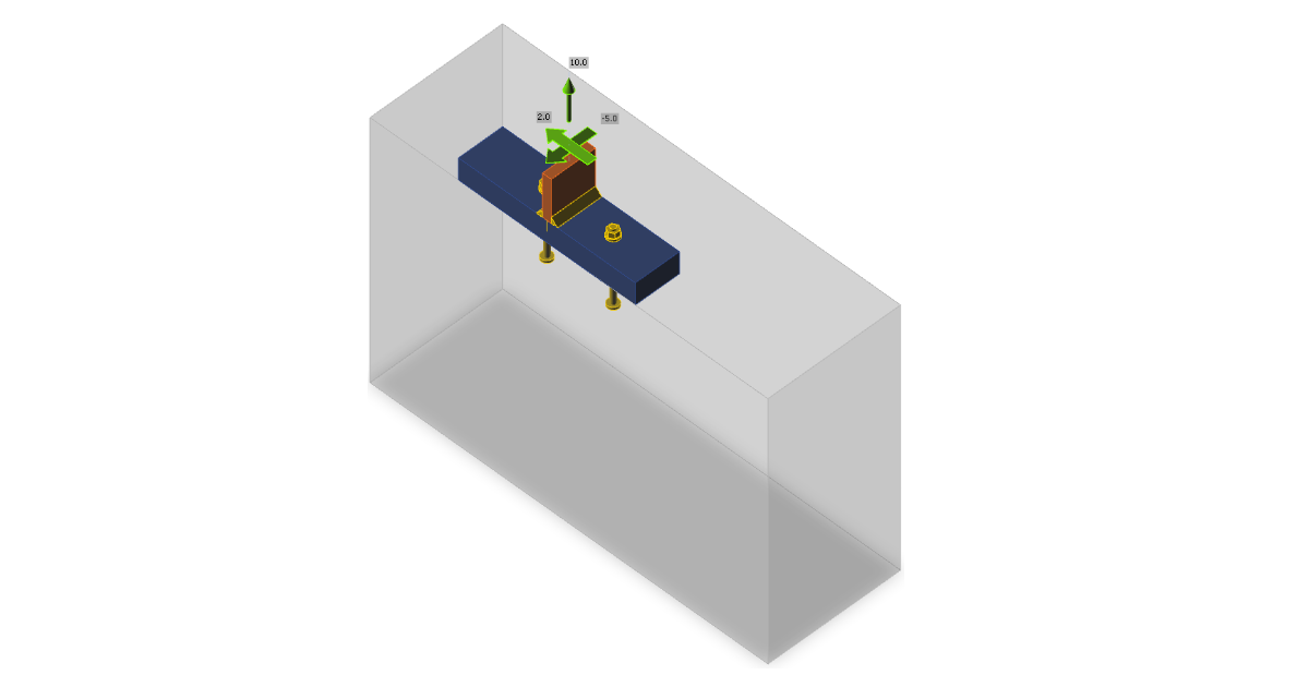
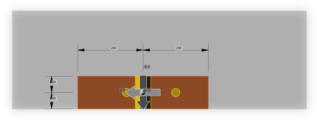
La disposition des ancrages et la section en T platine de base–poteau sont irréalistes, mais elles servent à vérifier la plupart des fonctionnalités de la conception des ancrages. Le décalage du bloc de béton par rapport à la platine de base est de 200 mm vers le haut et vers la gauche, 300 mm vers la droite et 0 mm vers le bas. La hauteur du bloc de béton est de 600 mm. Les ancrages gauche et droit sont respectivement à 50 mm et 100 mm du centre du poteau. Cela permet d'obtenir une excentricité des charges de traction et de cisaillement. Toutes les platines sont conçues pour rester en état élastique.
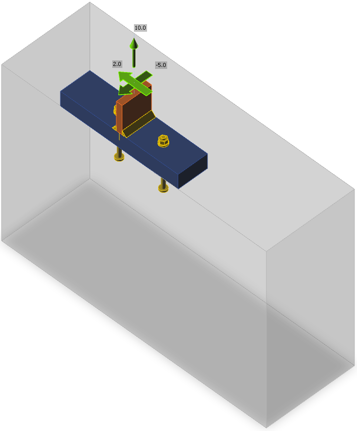
Charge appliquée
Le poteau est chargé par un effort de traction de 10 kN et des efforts de cisaillement dans les directions y et z, –5 kN et 2 kN. Les efforts de traction et de cisaillement agissent avec une excentricité due à la position des ancrages.
Procédure
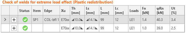
Les ancrages sont dimensionnés conformément à l'ACI 318-14 – Chapitre 17. Du béton non armé fissuré est supposé dans le calcul. Toutes les charges sont considérées comme statiques. Les ancrages sont des M12 A325M, coulés en place à tête avec des rondelles circulaires d'un diamètre de 24 mm. Les efforts de cisaillement sont transmis par les ancrages. La résistance des platines et des soudures est suffisante et n'est pas vérifiée ici.
Remarque : La conversion des unités impériales en unités métriques des formules non homogènes est présentée à l'Annexe B de l'ACI 318-14. Les formules donnent des résultats similaires mais pas exactement identiques. Pour éviter un taux de travail différent selon les unités impériales et métriques, les unités impériales sont privilégiées et les coefficients des formules non homogènes sont légèrement modifiés pour les unités métriques ; par exemple, dans l'Équation 17.4.4.1, au lieu du coefficient 13, le coefficient plus précis 13,2855 est utilisé.
Calcul manuel
La vérification des ancrages est effectuée conformément à l'ACI 318-14 – Chapitre 17. La résistance de l'acier en traction et en cisaillement ainsi que la résistance à l'arrachement sont fournies pour les ancrages individuels, et la résistance à l'éclatement du béton en traction et en cisaillement, la résistance à l'éclatement latéral du béton et la résistance au soulèvement du béton sont fournies pour un groupe d'ancrages. Il est supposé que le béton est non armé et en état fissuré.
Distribution des efforts
L'effort de traction est transmis par 2 ancrages, l'un se trouvant à 50 mm de l'origine du vecteur de force, l'autre à 100 mm. Il est supposé que l'ancrage le plus proche transmet 2/3 de l'effort de traction et le plus éloigné 1/3, c'est-à-dire que l'ancrage le plus proche est chargé par un effort de traction Nf1 = 6,67 kN, le plus éloigné par Nf2 = 3,33 kN. L'excentricité de l'effort du groupe d'ancrages est de 25 mm.
L'effort de cisaillement dans la direction vers le bord le plus proche est transmis par 2 ancrages, l'un se trouvant à 50 mm de l'origine du vecteur de force, l'autre à 100 mm. Il est supposé que l'ancrage le plus proche transmet 2/3 de l'effort de cisaillement et le plus éloigné 1/3, c'est-à-dire que l'ancrage le plus proche est chargé par un effort de cisaillement Vfx1 = 3,33 kN, le plus éloigné par Vfx2 = 1,67 kN. L'excentricité de l'effort du groupe d'ancrages est de 25 mm. L'effort de cisaillement dans la direction parallèle au bord le plus proche, 2 kN, est réparti également entre les deux ancrages. Les sommes vectorielles des efforts de cisaillement sont Vf1 = 3,48 kN, Vf2 = 1,94 kN, et pour un groupe d'ancrages Vf = 5,39 kN.
Résistance de l'acier de l'ancrage en traction
La résistance de l'acier de l'ancrage en traction est déterminée conformément à l'ACI 318-14 – 17.4.1 comme suit
ϕNsa = ϕ Ase,Nfuta = 0,7 ⋅ 84 ⋅ 827,4 = 48,7 kN ≥ Nf1 = 6,67 kN
où :
- ϕ = 0,7 – facteur de réduction de résistance pour les ancrages en traction conformément à l'ACI 318-14 – 17.3.3
- Ase,N = 84 mm2 – aire de la section résistante en traction
- futa = 827,4 MPa – résistance en traction spécifiée de l'acier d'ancrage, ne devant pas dépasser 1,9 fya ni 120 ksi
Taux de travail : Nf1 / ϕNsa = 6,67 / 48,7 = 13,7 %
Résistance à l'éclatement du béton en traction
La résistance à l'éclatement du béton est dimensionnée conformément à la méthode de conception de la capacité du béton (CCD) de l'ACI 318-14 – Chapitre 17.4.2. Les ancrages sont traités comme un groupe car ils sont proches les uns des autres, l'espacement s = 150 mm ≤ 3 ⋅ hef = 3 ⋅ 100 = 300 mm.
\[ \phi N_{cbg} = \phi \frac{A_{Nc}}{A_{Nco}} \psi_{ec,N} \psi_{ed,N} \psi_{c,N} \psi_{cp,N} N_b \]
où :
- ϕ = 0,7 – facteur de réduction de résistance pour les ancrages en traction conformément à l'ACI 318-14 – 17.3.3
- ANc = (50 + 150 + 12) ⋅ (150 + 12 + 150 + 12 + 150) = 100 488 mm2 – aire réelle du cône d'éclatement du béton pour un groupe d'ancrages formant un cône de béton commun. Conformément à l'Art. 17.4.2.8, l'aire projetée de la surface de rupture est obtenue en projetant la surface de rupture vers l'extérieur à partir du périmètre effectif de la rondelle.
- ANco = 9 hef2 = 9 ⋅ 1002 = 90 000 mm2 – aire du cône d'éclatement du béton pour un ancrage isolé non influencé par les bords
- \( \psi_{ec,N} = \frac{1}{1+\frac{2 e'_N}{3 h_{ef}}} = \frac{1}{1+\frac{2 \cdot 25}{3 \cdot 100}}=0.857 \) – facteur de modification pour les groupes d'ancrages chargés de manière excentrique en traction
- \( \psi_{ed,N} = \min \left ( 0.7 + \frac{0.3 c_{a,min}}{1.5 h_{ef}}, 1 \right ) = \min \left ( 0.7 + \frac{0.3 \cdot 50}{1.5 \cdot 100}, 1 \right ) = 0.8 \) – facteur de modification pour la distance au bord
- ca,min = 50 mm – distance minimale de l'ancrage au bord
- Ψc,N = 1 – facteur de modification pour les conditions du béton
- Ψcp,N = 1 pour ancrage coulé en place
- \( N_b = k_c \lambda_a \sqrt{f'_c} h_{ef}^{1.5} = 10 \cdot 1 \cdot \sqrt{27.6} \cdot 100^{1.5} = 52.7 \,\textrm{kN} \)– résistance de base à l'éclatement du béton d'un ancrage isolé en traction dans un béton fissuré ; hef ≤ 280 mm (11 in)
- kc = 10 pour les ancrages coulés en place et les unités métriques
- hef = 100 mm – profondeur de scellement ; conformément à l'Art. 17.4.2.3 de l'ACI 318-14, la profondeur de scellement effective hef est réduite à \( h_{ef} = \max \left ( \frac{c_{a,max}}{1.5}, \frac{s}{3} \right ) \)
- si les ancrages sont situés à moins de 1,5 hef de trois bords ou plus
- s = 150 mm – espacement entre les ancrages
- ca,max = 350 mm – distance maximale d'un ancrage à l'un des trois bords proches
- λa = 1 – facteur de modification pour le béton léger
- f'c = 27,6 MPa – résistance en compression du béton
\[ \phi N_{cbg} = 0.7 \cdot \frac{100488}{90000} \cdot 0.857 \cdot 0.8 \cdot 1 \cdot 1 \cdot 52.7 = 28.3 \,\textrm{kN} \ge N_f = 10\,\textrm{kN} \]
Taux de travail : Nf / ϕNcbg = 10 / 28,3 = 35,4 %
Résistance à l'arrachement en traction
La résistance à l'arrachement du béton d'un ancrage est définie dans l'ACI 318-14 – 17.4.3 comme suit
ϕNpn = ϕΨc,PNp = 0,7 ⋅ 1 ⋅ 74,9 = 52,4 kN ≥ Nf1 = 6,67 kN
où :
- ϕ = 0,7 – facteur de réduction de résistance pour les ancrages en traction conformément à l'ACI 318-14 – 17.3.3
- Ψc,P = 1 – facteur de modification pour les conditions du béton, Ψc,P = 1,0 pour le béton fissuré
- NP = 8 Abrgf'c = 8 ⋅ 339,3 ⋅ 27,6 = 74,9 kN – pour ancrage à tête – Art. 17.4.3.4
- Abrg = π ⋅ (dwp2 – da2) / 4 = π ⋅ (242 – 122) / 4 = 339,3 mm2– aire d'appui de la tête du boulon d'ancrage
- f'c = 27,6 MPa – résistance en compression du béton
Taux de travail : Nf1 / ϕNpn = 6,67 / 52,4 = 12,7 %
Résistance à l'éclatement latéral du béton
La résistance à l'éclatement latéral du béton d'un ancrage à tête en traction est définie dans l'ACI 318-14 – 17.4.4 comme suit
\[ \phi N_{sb} = \phi 13 c_{a1} \sqrt{A_{brg}} \sqrt{f'_c} \]
La résistance à l'éclatement latéral du béton est multipliée par un facteur de réduction pour les ancrages à tête multiples proches d'un bord et proches les uns des autres conformément à l'Art. 17.4.4.2 :
\[ 1+\frac{s}{6 c_{a1}} = 1+\frac{150}{6 \cdot 50} = 1.5 \le 2 \]
où :
- ϕ = 0,7 – facteur de réduction de résistance pour les ancrages en traction conformément à l'ACI 318-14 – 17.3.3
- ca1 = 50 mm – distance la plus courte entre l'axe d'un ancrage et un bord
- ca2 = 350 mm – distance la plus longue, perpendiculaire à ca1, entre l'axe d'un ancrage et un bord
- Abrg = 339,3 mm2 – aire d'appui de la tête du boulon d'ancrage
- f'c = 27,6 MPa – résistance en compression du béton
- hef = 100 mm – profondeur de scellement
- s = 150 mm – espacement entre les ancrages
\[ \phi N_{sbg} = 1.5 \cdot \phi 13 c_{a1} \sqrt{A_{brg}} \sqrt{f'_c} = 1.5 \cdot 0.7 \cdot 13 \cdot 50 \cdot \sqrt{339.3} \cdot \sqrt{27.6} = 67.4\,\textrm{kN} \ge N_{f} = 10\,\textrm{kN} \]
Taux de travail : Nf / ϕNcbg = 10 / 67,4 = 26,7 %
Résistance de l'acier en cisaillement
La résistance de l'acier en cisaillement est déterminée conformément à l'ACI 318-14 – 17.5.1 comme suit
ϕVsa = ϕ 0,6 Ase,Vfuta = 0,65 ⋅ 0,6 ⋅ 84 ⋅ 827,4 = 27,1 kN ≥ Vf1 = 3,48 kN
où :
- ϕ = 0,65 – facteur de réduction de résistance pour les ancrages en traction conformément à l'ACI 318-14 – 17.3.3
- Ase,V = 84 mm2 – aire de la section résistante en traction
- futa = 827,4 MPa – résistance en traction spécifiée de l'acier d'ancrage, ne devant pas dépasser 1,9 fya ni 120 ksi
Taux de travail : Vf1 / ϕVsa = 3,48 / 27,1 = 12,7 %
Résistance à l'éclatement du béton en cisaillement
La résistance à l'éclatement du béton d'un groupe d'ancrages en cisaillement est dimensionnée conformément à l'ACI 318-14 – 17.5.2.
\[ \phi V_{cbg} = \phi \frac{A_V}{A_{Vo}} \psi_{ec,V} \psi_{ed,V} \psi_{c,V} \psi_{h,V} \psi_{\alpha,V} V_b \]
où :
- ϕ = 0,65 – facteur de réduction de résistance pour les ancrages en cisaillement conformément à l'ACI 318-14 – 17.3.3
- Av = (50 ⋅ 1,5) ⋅ (50 ⋅ 1,5 + 150 + 50 ⋅ 1,5) = 22 500 mm2 – aire projetée de rupture du béton d'un ancrage ou d'un groupe d'ancrages
- Avo = 4,5 ca12 = 4,5 ⋅ 502 = 11 250 mm2 – aire projetée de rupture du béton d'un ancrage isolé sans influence de coin, d'espacement ou d'épaisseur de l'élément
- \( \psi_{ec,V} = \frac{1}{1+\frac{2 e'_V}{3 c_{a1}}}= \frac{1}{1+\frac{2 \cdot 25}{3 \cdot 50}}=0.75 \) – facteur de modification pour les groupes d'ancrages chargés de manière excentrique en cisaillement
- \( \psi_{ed,V} = 0.7 + 0.3 \frac{c_{a2}}{1.5 c_{a1}} = 0.7 + 0.3 \frac{350}{1.5 \cdot 50} = 2.1\le 1.0 \) – facteur de modification pour l'effet de bord
- Ψc,V = 1 – facteur de modification pour les conditions du béton ; Ψc,V = 1,0 pour le béton fissuré
- \( $\psi_{h,V} = \sqrt{\frac{1.5 c_{a1}}{h_a}} = \sqrt{\frac{1.5 \cdot 50}{600}} = 0.354 \ge 1 \)– facteur de modification pour les ancrages situés dans un élément en béton où ha < 1,5 ca1
- \( \psi_{\alpha ,V} = \sqrt{\frac{1}{(\cos \alpha_V )^2 + (0.5 \sin \alpha_V)^2}}=\sqrt{\frac{1}{(\cos 21.8^\circ )^2 + (0.5 \sin 21.8^\circ)^2}} = 1.056 \)– facteur de modification pour les ancrages chargés à un angle 90° − αV par rapport au bord du béton ; dans l'ACI 318-14 – 17.5.2.1, seules des valeurs discrètes sont données, l'équation est tirée du bulletin FIB 58 – Design of anchorages in concrete (2011)
- ha = 600 mm – hauteur de la surface de rupture côté béton
\[ V_b = \min \left ( 0.6 \left ( \frac{l_e}{d_a} \right )^{0.2} \lambda_a \sqrt{d_a} \sqrt{f'_c} c_{a1}^{1.5}, 3.7 \lambda_a \sqrt{d_a} \sqrt{f'_c} c_{a1}^{1.5} \right ) \]
\[ V_b = \min \left ( 0.6 \left ( \frac{96}{12} \right )^{0.2} \cdot 1.0 \cdot \sqrt{12} \cdot \sqrt{27.6} \cdot 50^{1.5} = 5.666 \, \textrm{kN}, 3.7 \cdot 1.0 \cdot \sqrt{12} \cdot \sqrt{27.6} \cdot 50^{1.5} = 6.993 \, \textrm{kN} \right ) = 5.666 \, \textrm{kN} \]
- le = hef = 100 mm ≤ 8 da = 8 ⋅ 12 = 96 mm – longueur portante de l'ancrage en cisaillement
- da = 12 mm – diamètre de l'ancrage
- f'c = 27,6 MPa – résistance en compression du béton
- ca1 = 50 mm – distance au bord dans la direction de la charge, ca2 ≥ 1,5 ca1 et ha ≥ 1,5 ca1
- ca2 = 350 mm – distance au bord dans la direction perpendiculaire à la charge
\[ \phi V_{cbg} = 0.65 \cdot \frac{22500}{11250} \cdot 0.75 \cdot 1.0 \cdot 1.0 \cdot 1.0 \cdot 1.056 \cdot 5.666 = 5.835 \, \textrm{kN} \ge V_f = 5.39 \, \textrm{kN} \]
Taux de travail : Vf / ϕVcbg = 5,39 / 5,835 = 92,3 %
Résistance au soulèvement du béton de l'ancrage en cisaillement
La résistance au soulèvement du béton est dimensionnée conformément à l'ACI 318-14 – 17.5.3. Il est supposé que tous les ancrages sont en traction et qu'il n'y a pas d'excentricité pour la résistance à l'éclatement du béton.
ϕVcp = ϕkcpNcp = 0,65 ⋅ 2 ⋅ 47,1 = 61,2 kN ≥ Vf = 5,39 kN
où :
- ϕ = 0,65 – facteur de réduction de résistance pour les ancrages en cisaillement conformément à l'ACI 318-14 – 17.3.3
- kcp = 2,0 pour hef ≥ 50 mm
- Ncp = Ncb = 47,1 kN (résistance à l'éclatement du béton – tous les ancrages sont supposés en traction) dans le cas d'ancrages coulés en place
Taux de travail : Vf / ϕVcp = 5,39 / 61,2 = 5,7 %
Interaction des efforts de traction et de cisaillement
L'interaction des efforts de traction et de cisaillement est évaluée conformément à l'ACI 318-14 – R17.6.
\[ \left ( \frac{N_{ua}}{N_n} \right )^{\zeta} + \left ( \frac{V_{ua}}{V_n} \right )^{\zeta} = \left ( 0.354 \right )^{5/3} + \left ( 0.923 \right )^{5/3}= 1.062 \le 1.0 \]
où :
- Nua et Vua – efforts de calcul agissant sur un ancrage
- Nn et Vn – les résistances de calcul les plus faibles déterminées à partir de tous les modes de rupture appropriés
- ς = 5 / 3
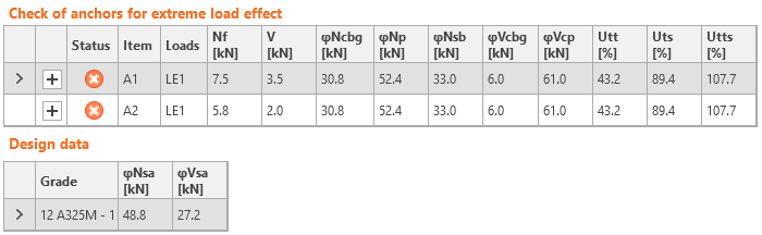
La résistance de l'ancrage est insuffisante pour transmettre les efforts combinés de traction et de cisaillement.
Vérification dans IDEA StatiCa Connection
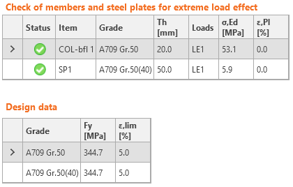
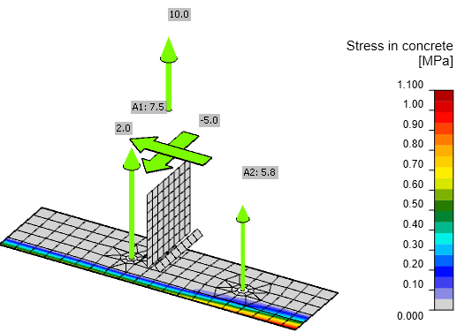
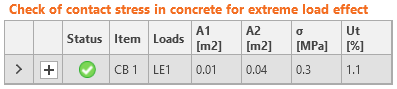
De plus, les résultats des soudures et du bloc de béton en compression sont présentés. Le chargement de ces composants est négligeable et, par conséquent, le taux de travail l'est également.
Comparaison
La distribution des efforts dans IDEA StatiCa Connection est légèrement différente de celle du calcul manuel. Le poteau et la platine de base sont déformés et la platine de base est en contact avec le bloc de béton. La contrainte d'appui augmente les efforts dans les ancrages. Ainsi, les facteurs tenant compte de l'excentricité des efforts sont légèrement différents. La résistance à l'éclatement latéral du béton est vérifiée dans IDEA StatiCa Connection pour chaque ancrage séparément, mais dans le calcul manuel, elle peut être vérifiée en groupe afin d'obtenir une résistance légèrement plus élevée. Pour ces raisons, certaines résistances individuelles aux charges sont légèrement différentes, mais seulement de quelques pourcents. Le taux de travail final – interaction des efforts de traction et de cisaillement – est presque identique : 106,2 % dans le calcul manuel et 107,7 % dans IDEA StatiCa.