
Diseño estructural de una zapata con diagonal (AISC)
1 Nuevo proyecto
Lancemos IDEA StatiCa y seleccionemos la aplicación Connection. Cree un nuevo proyecto seleccionando la plantilla inicial más cercana al diseño deseado, completando el nombre y eligiendo el código de diseño y las propiedades de material predeterminadas – A992.

Dado que trabaja bajo el código AISC, configure las unidades imperiales (consulte Cómo cambiar el sistema de unidades).
2 Geometría
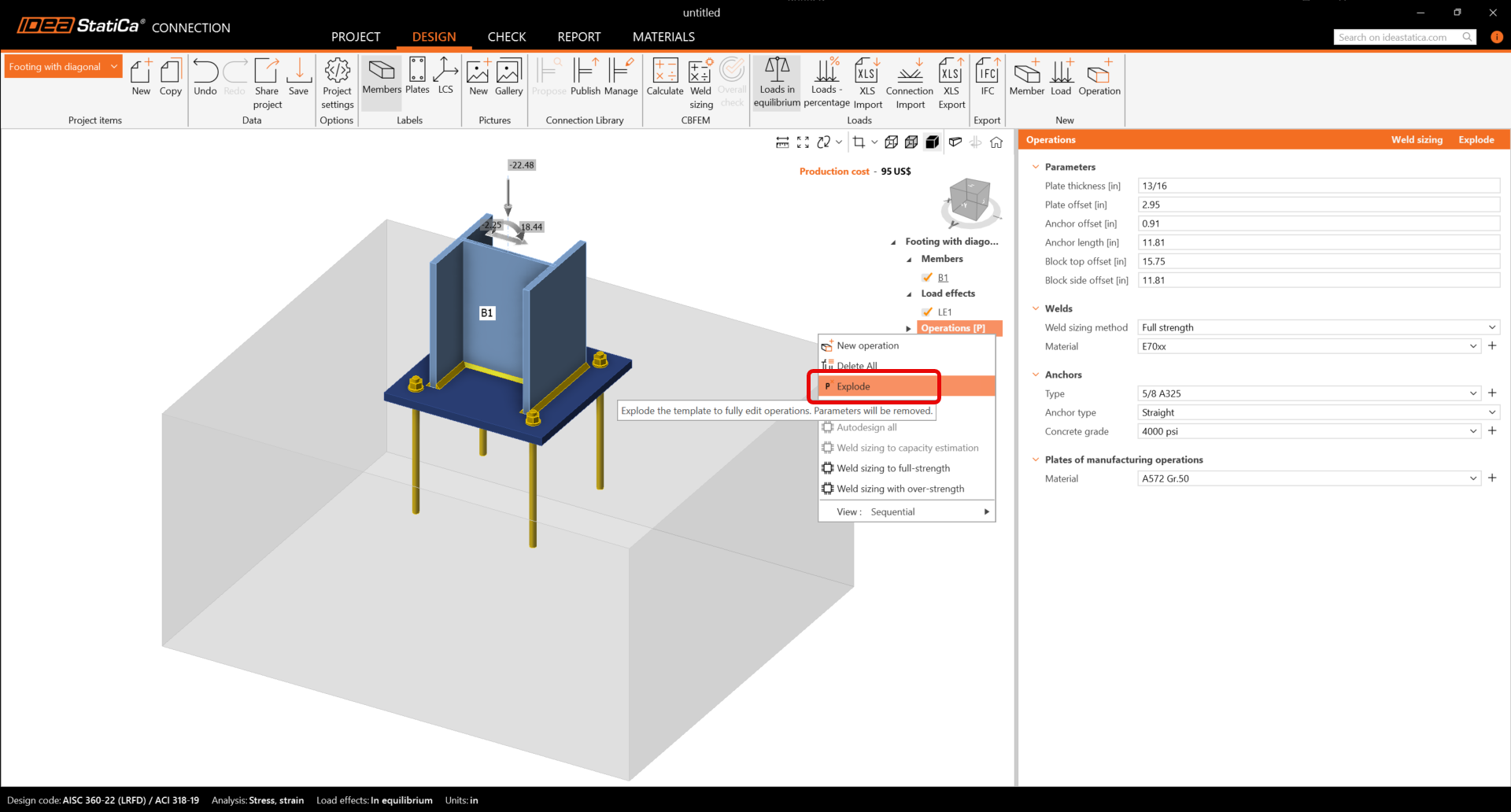
Se añadieron automáticamente una columna y una placa base con anclajes. Antes de continuar, asegúrese de descomponer la plantilla paramétrica como se muestra a continuación.
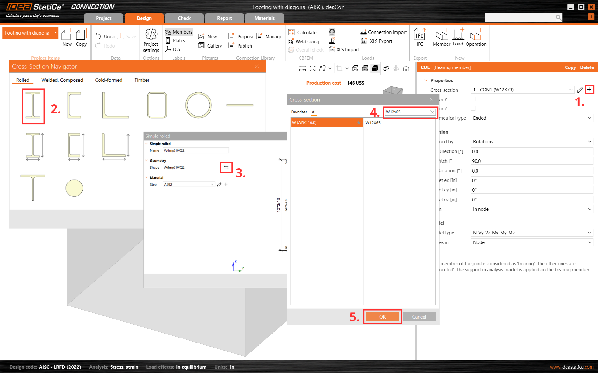
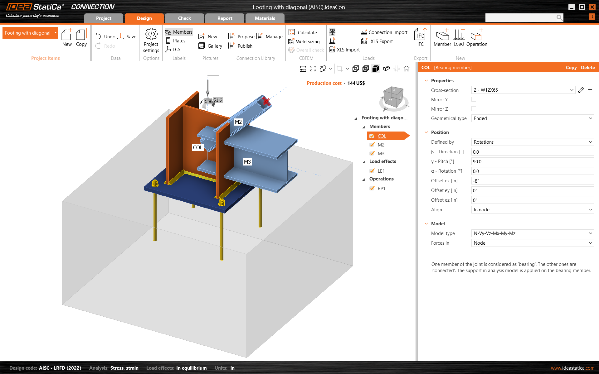
Primero, cambie la sección transversal de la columna.
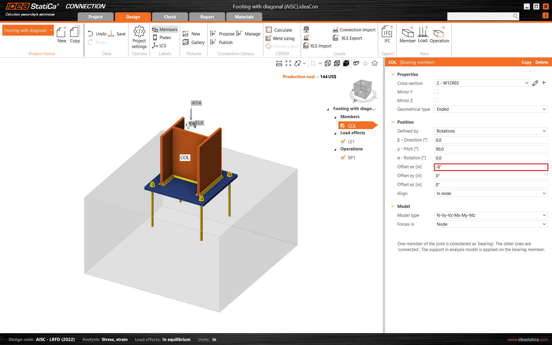
Y modifique su desplazamiento en la dirección ex.
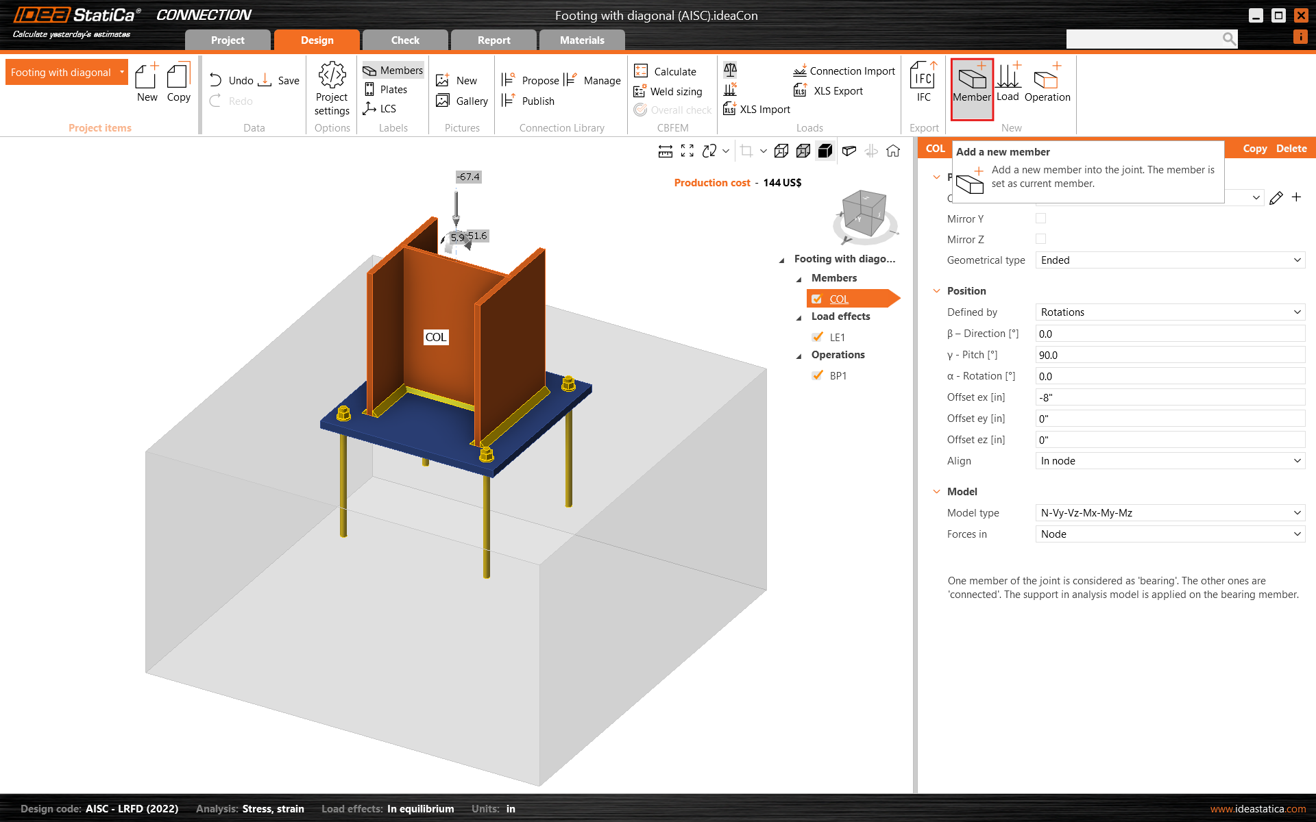
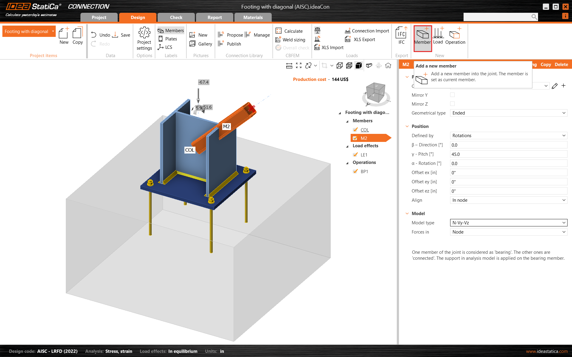
Luego añada un nuevo elemento.
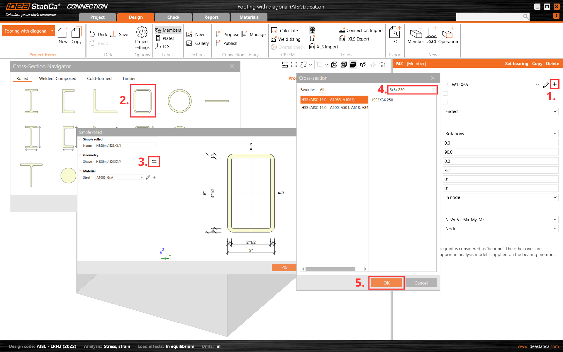
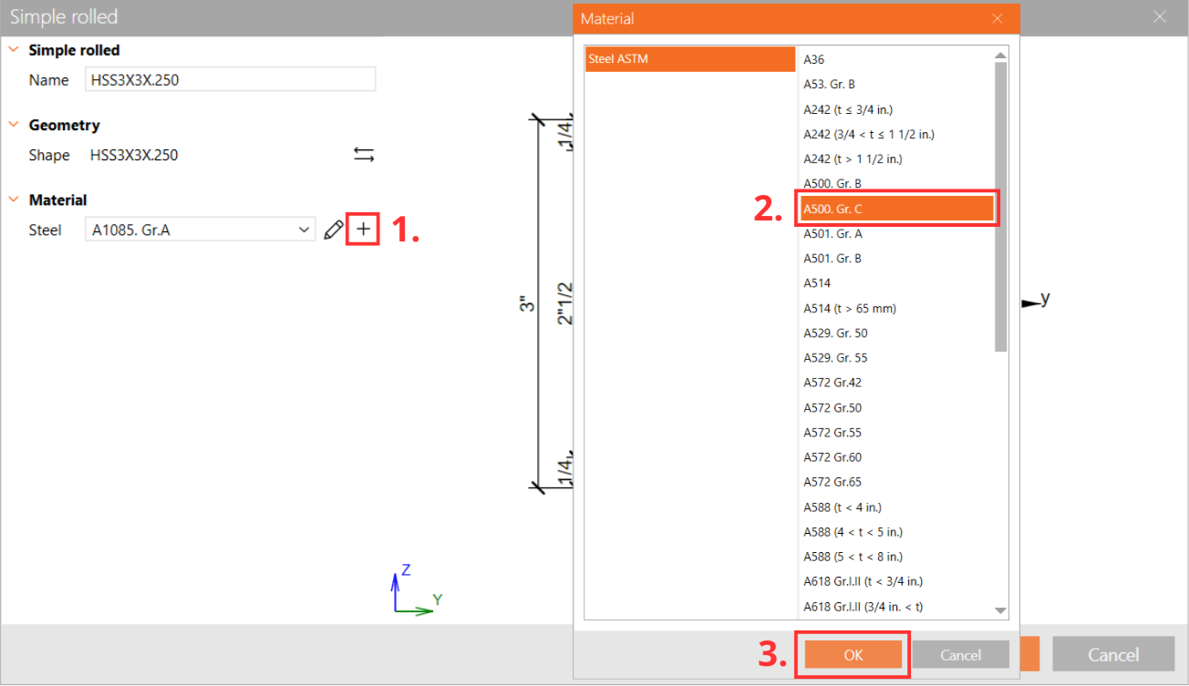
Y cambie su sección transversal a HSS3X3X1/4 y el material a A500 Grade C shaped
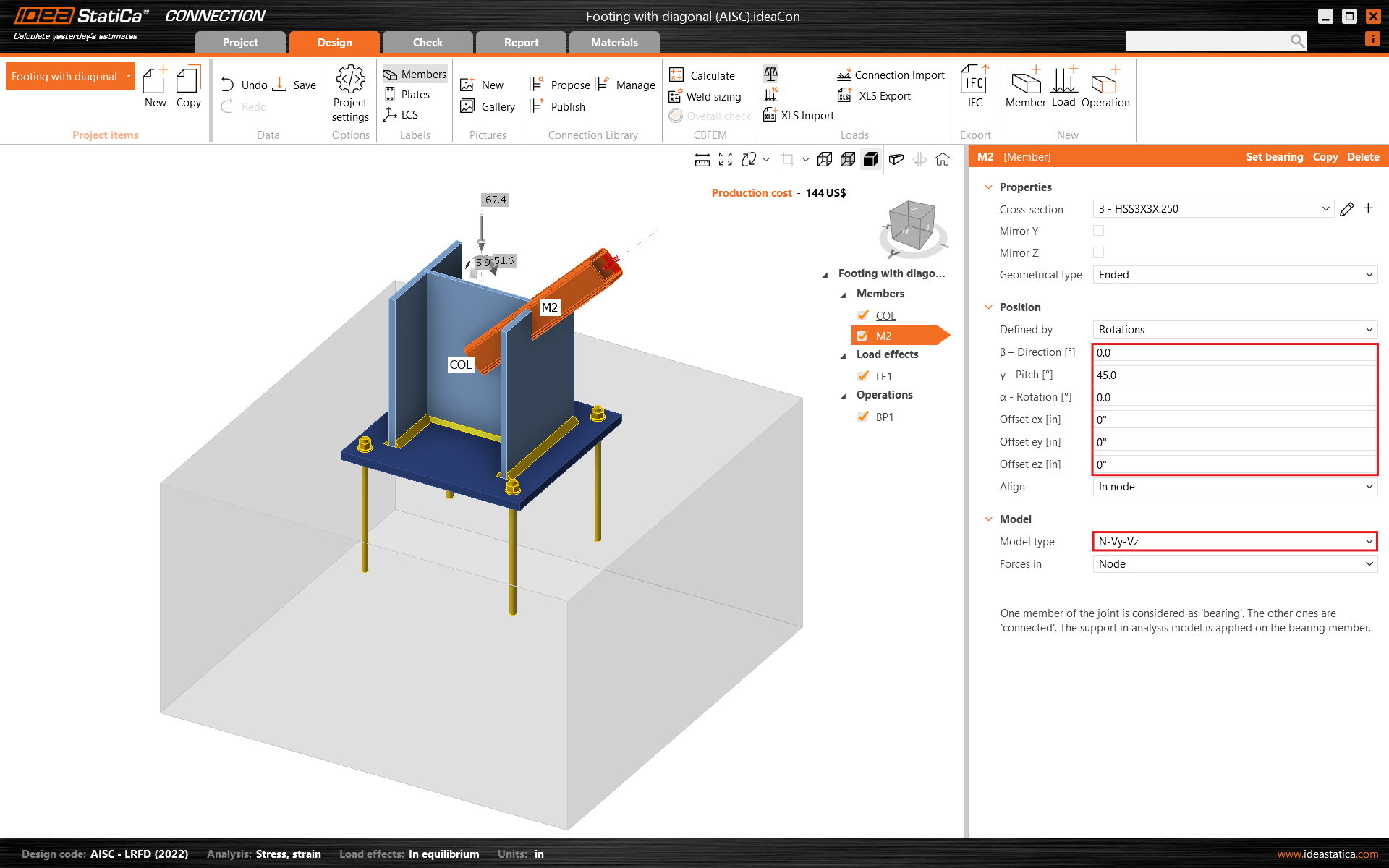
Cambie el ángulo de inclinación del elemento y establezca el tipo de modelo en N-Vy-Vz, ya que este elemento actuará solo a tracción/compresión como una diagonal de arriostramiento articulada.
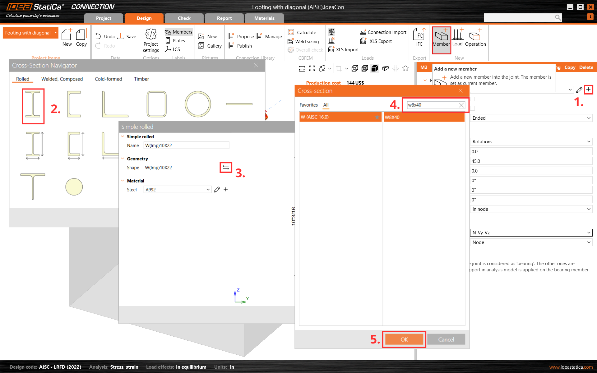
Añada otro elemento, cambie su sección transversal a W8X40 y modifique sus propiedades.
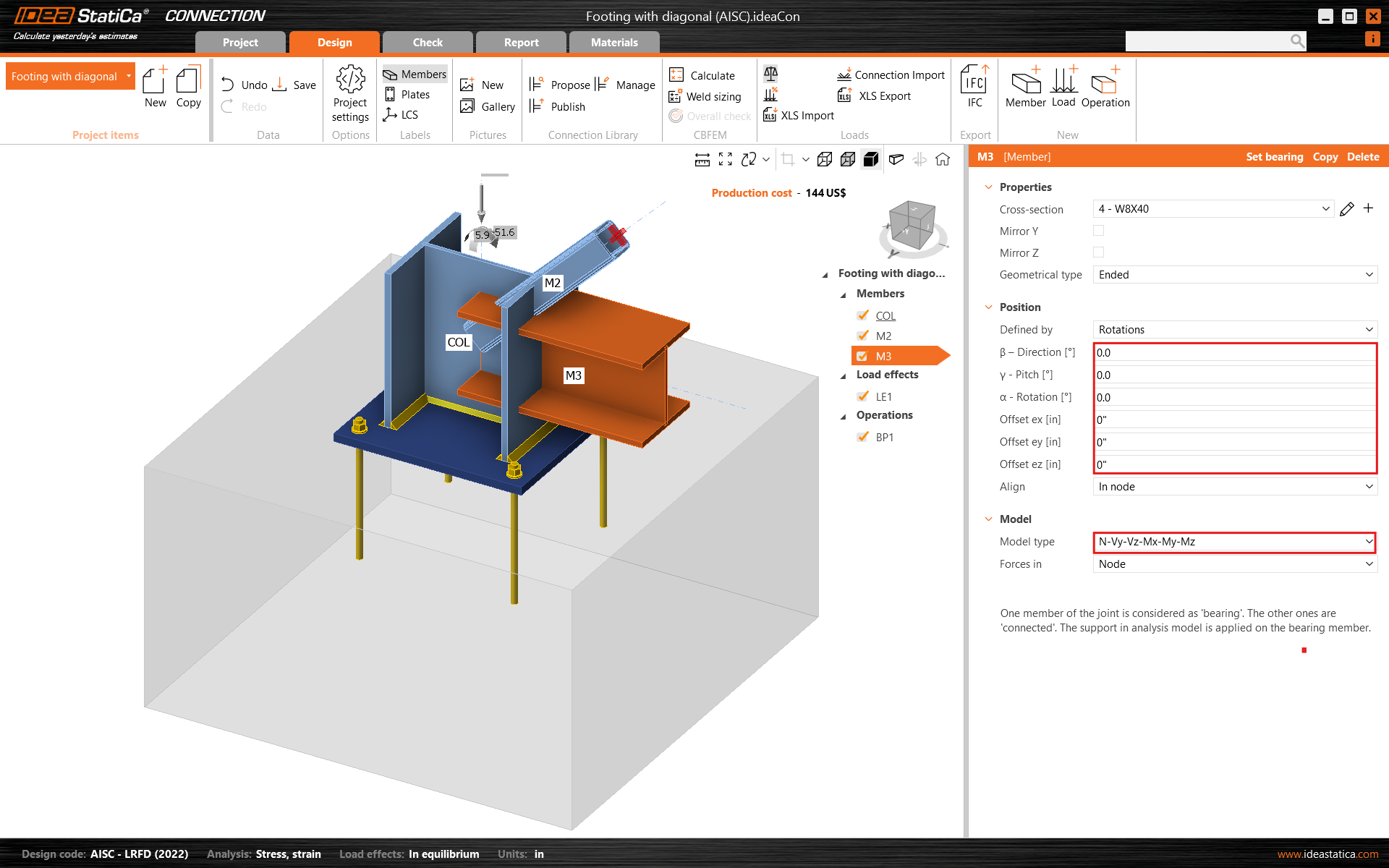
Compruebe la geometría de todos los elementos añadidos.
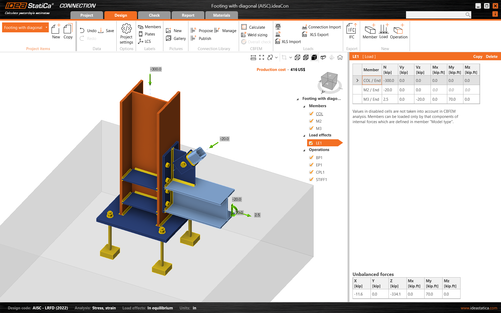
3 Efectos de carga
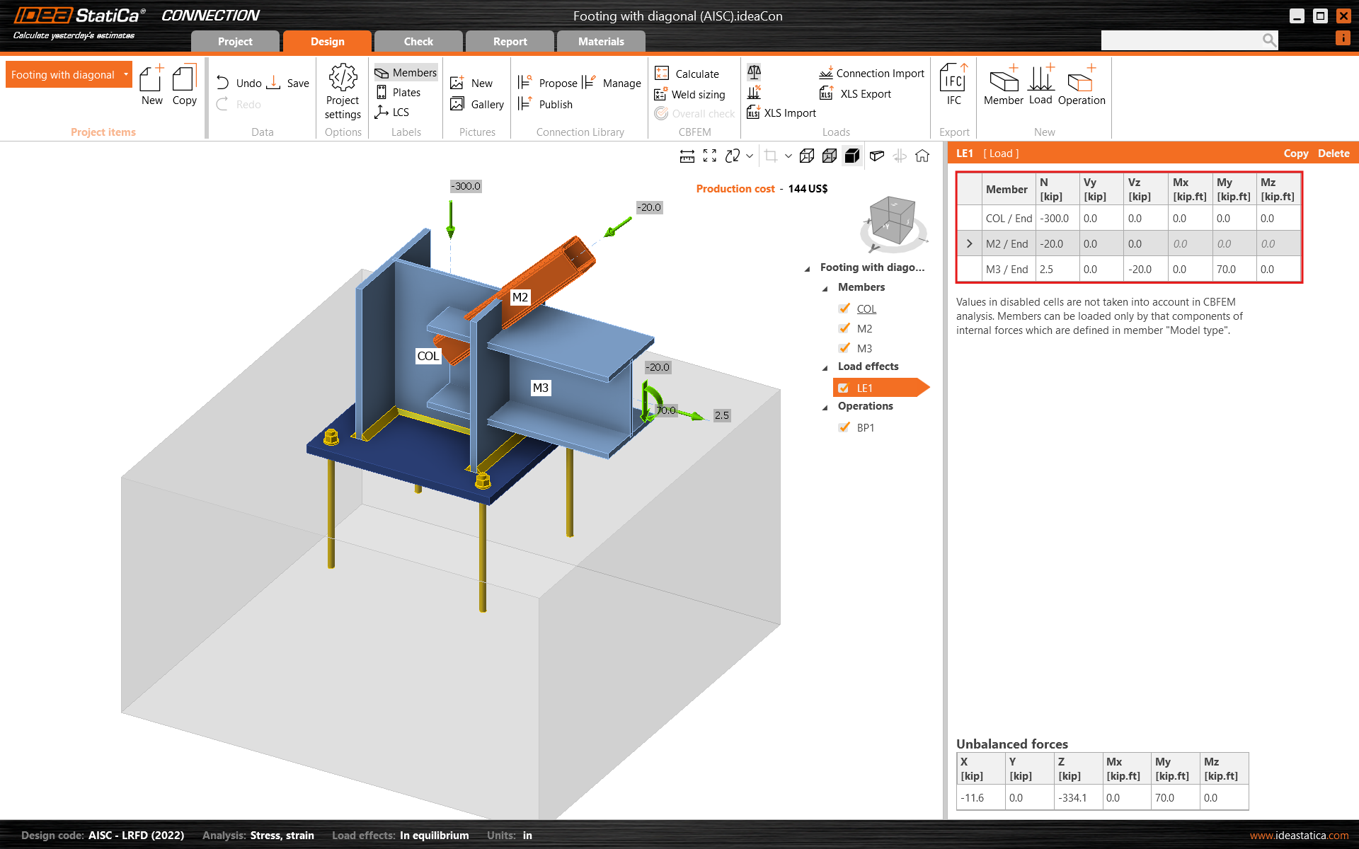
Se añadió automáticamente un efecto de carga. Introduzca los valores de las fuerzas internas en la tabla. Se pueden añadir más casos de carga.
4 Diseño
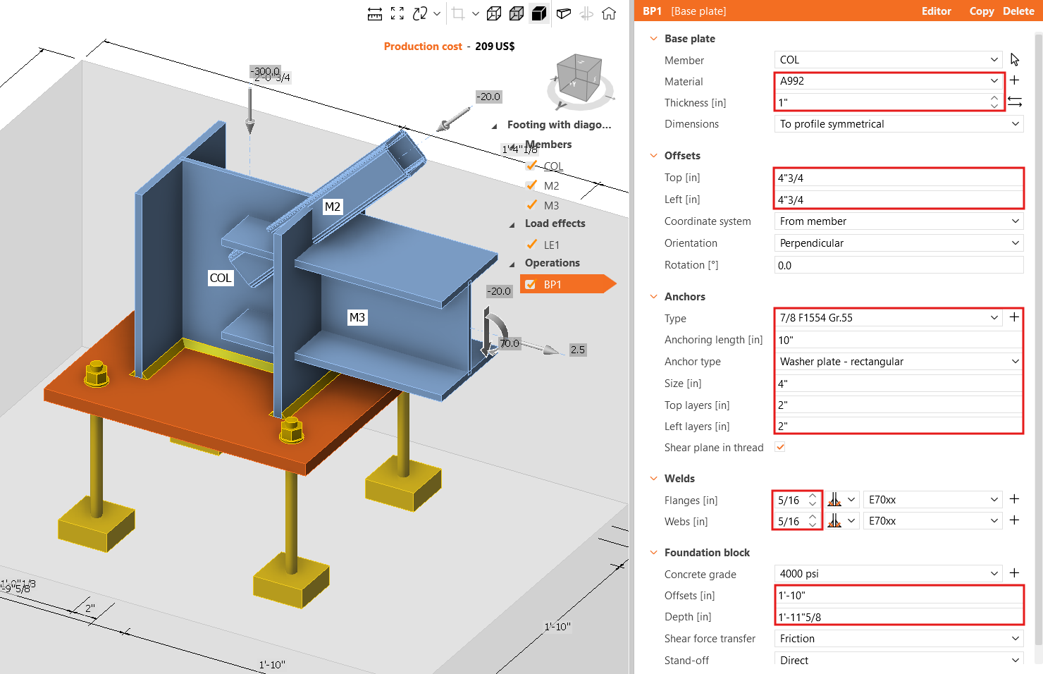
La operación de fabricación Placa base ya fue añadida. Solo actualice algunas de sus propiedades.
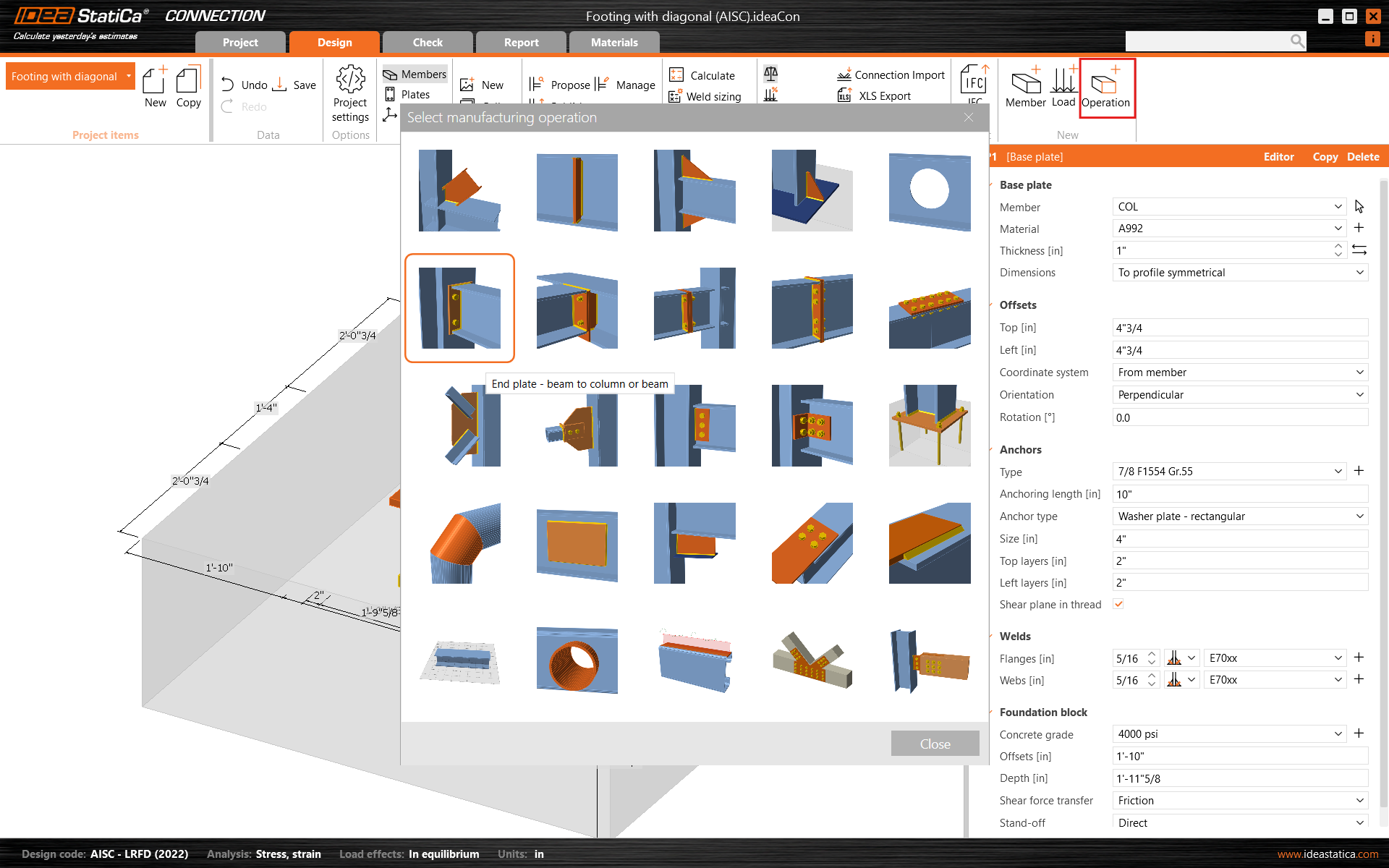
Continúe y añada otra operación de fabricación y seleccione la Placa de testa.
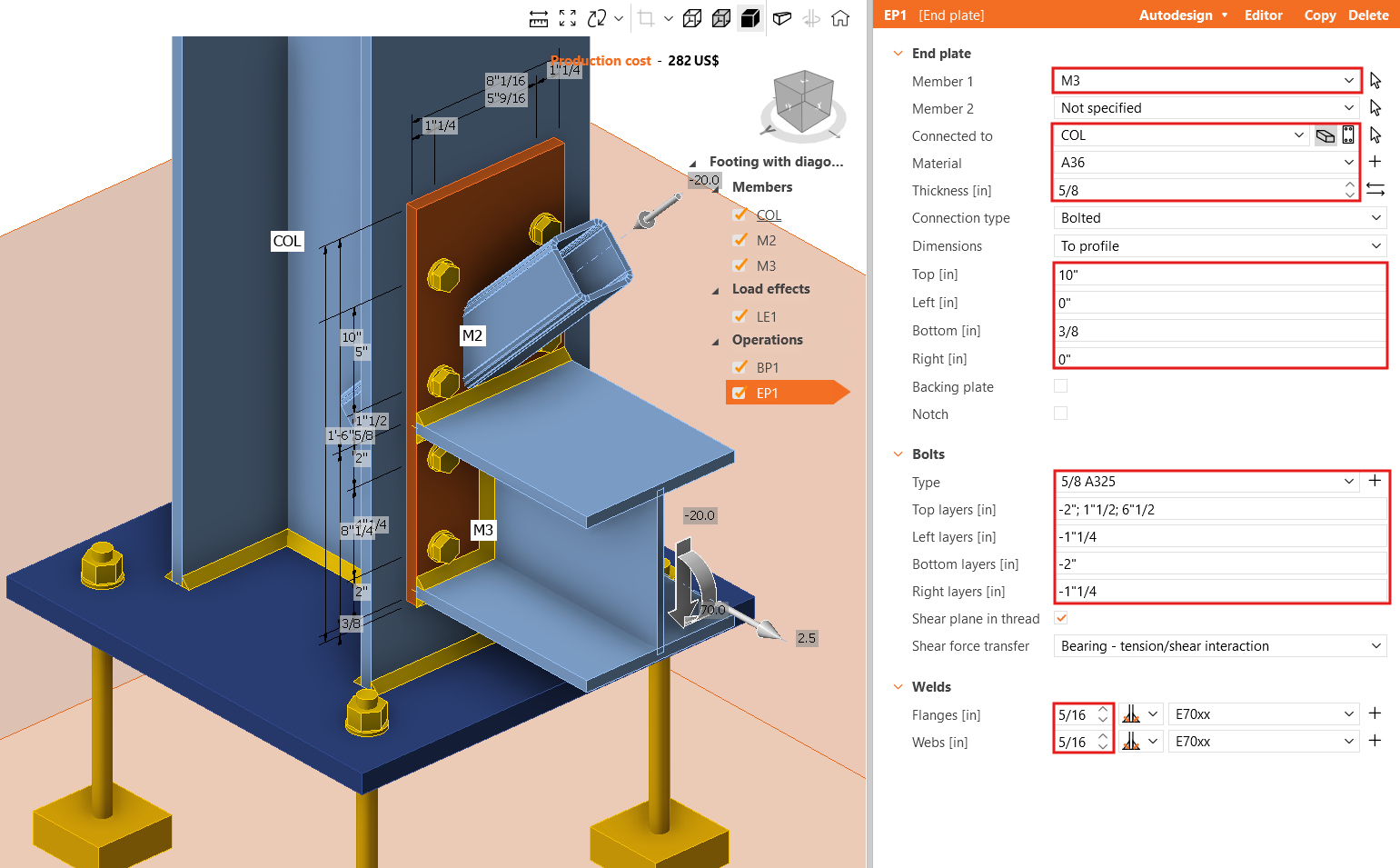
Modifique las propiedades de la operación EP1.
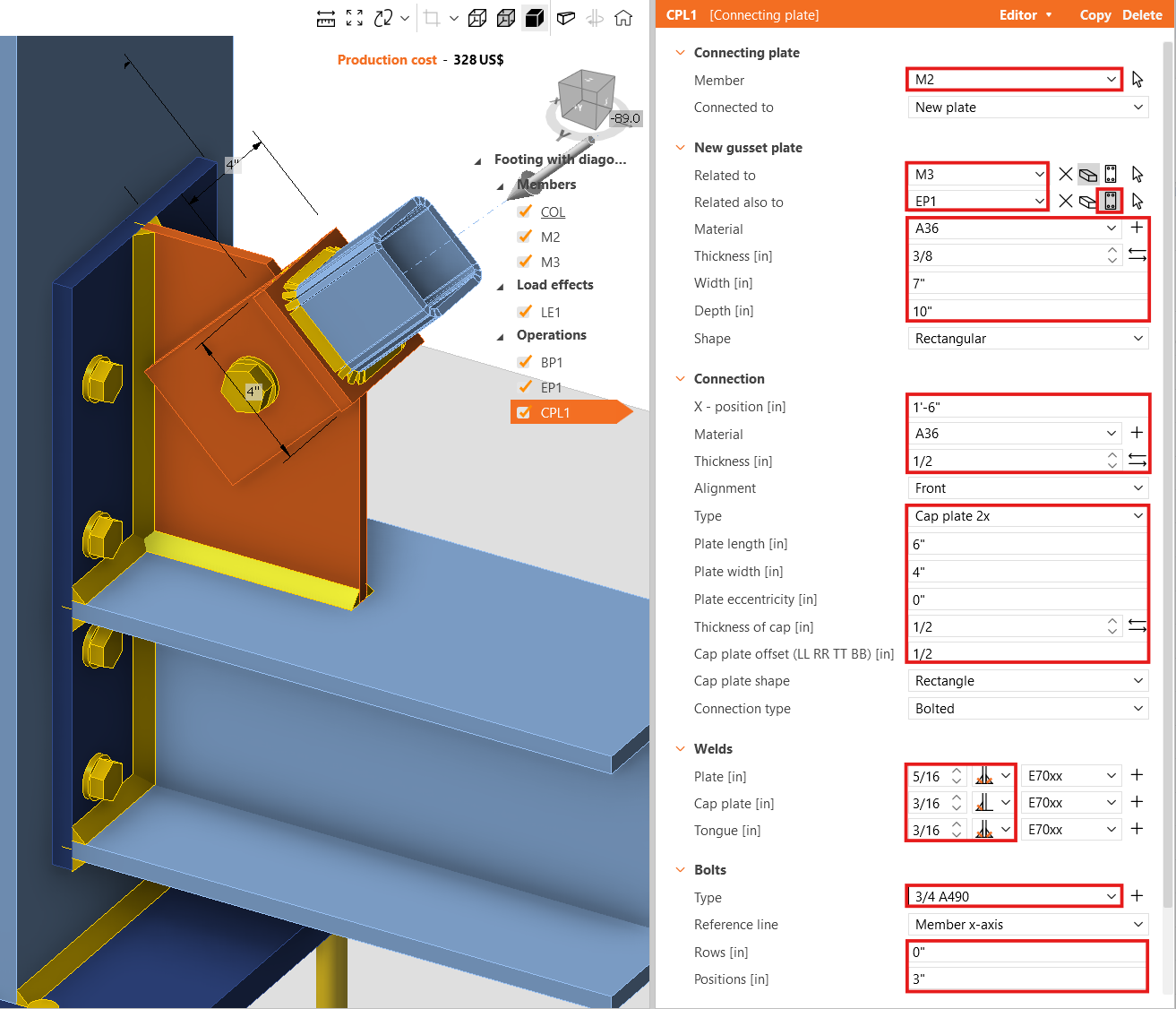
Ahora, añada la Placa de conexión.
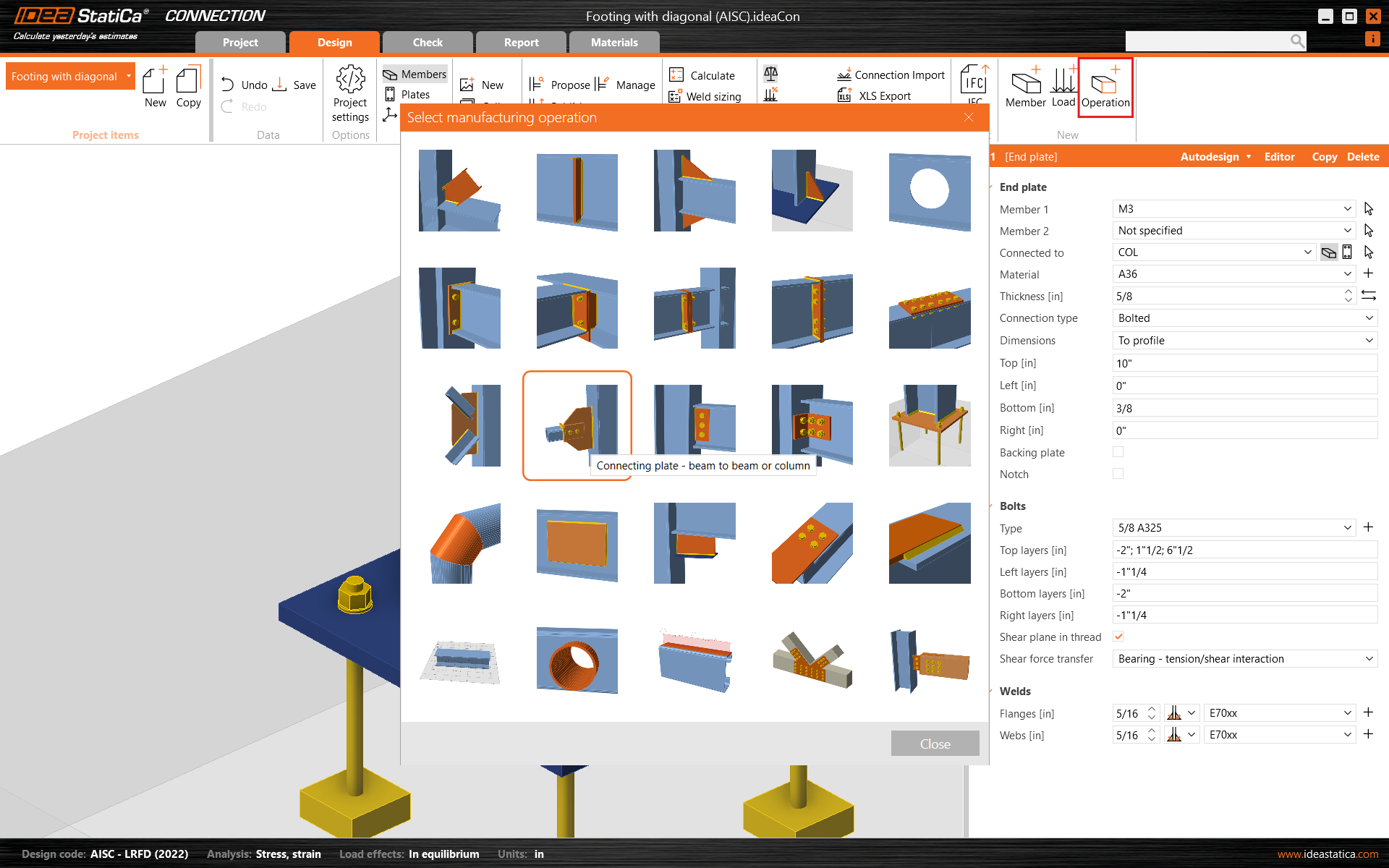
Y redefina sus propiedades.
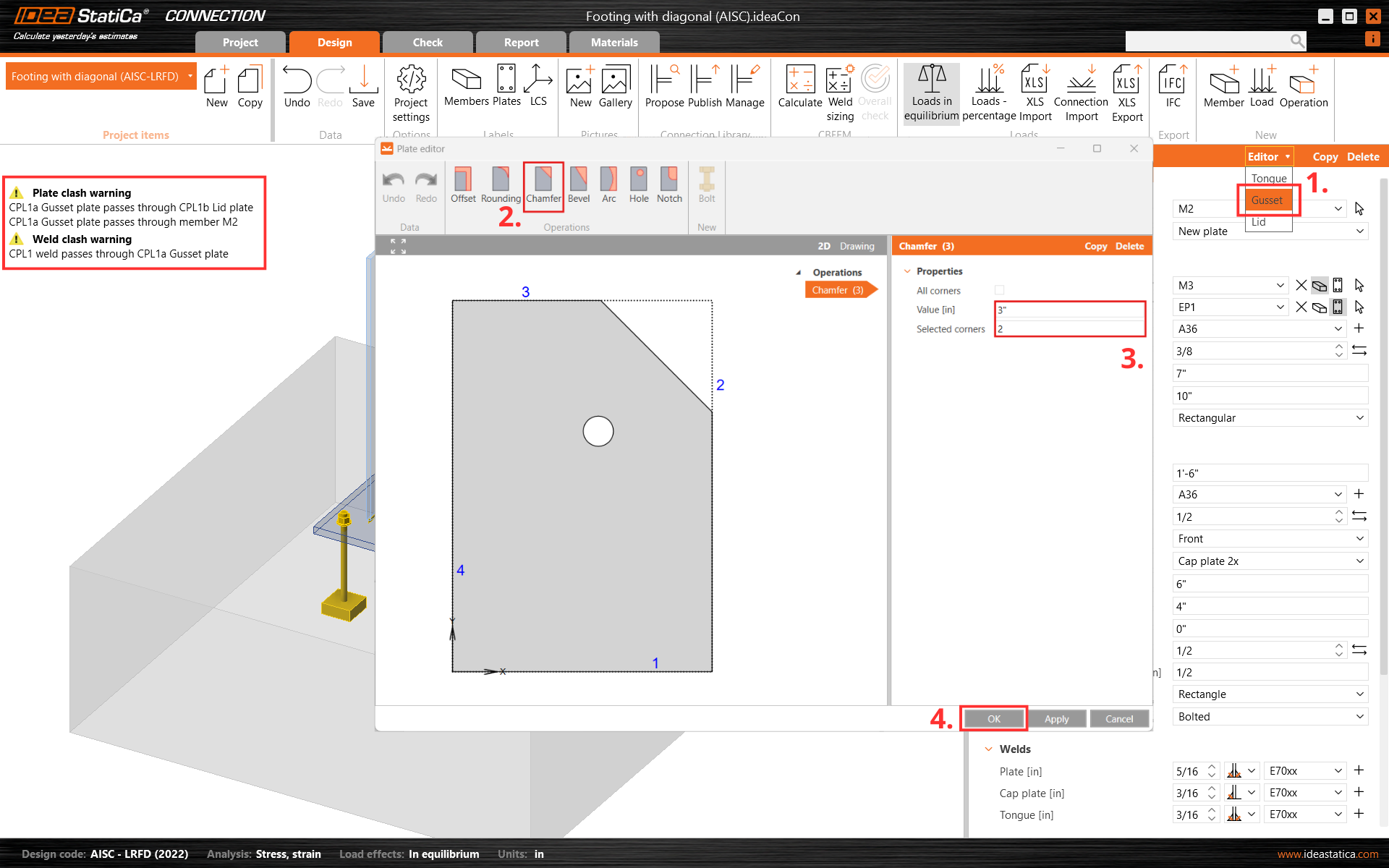
A continuación, corte una esquina de la placa de conexión CPL1. Para ello, vaya al Editor - Placa de unión y cree un Chaflán en la esquina número 2.
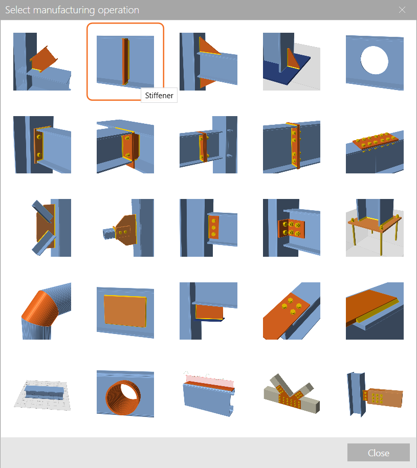
Finalice el diseño con la operación Rigidizador.
Y establezca las propiedades correctas de STIFF1.
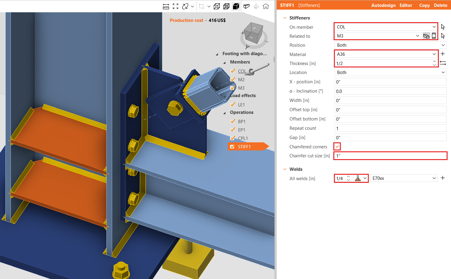
Comprobemos el diseño final de la junta.
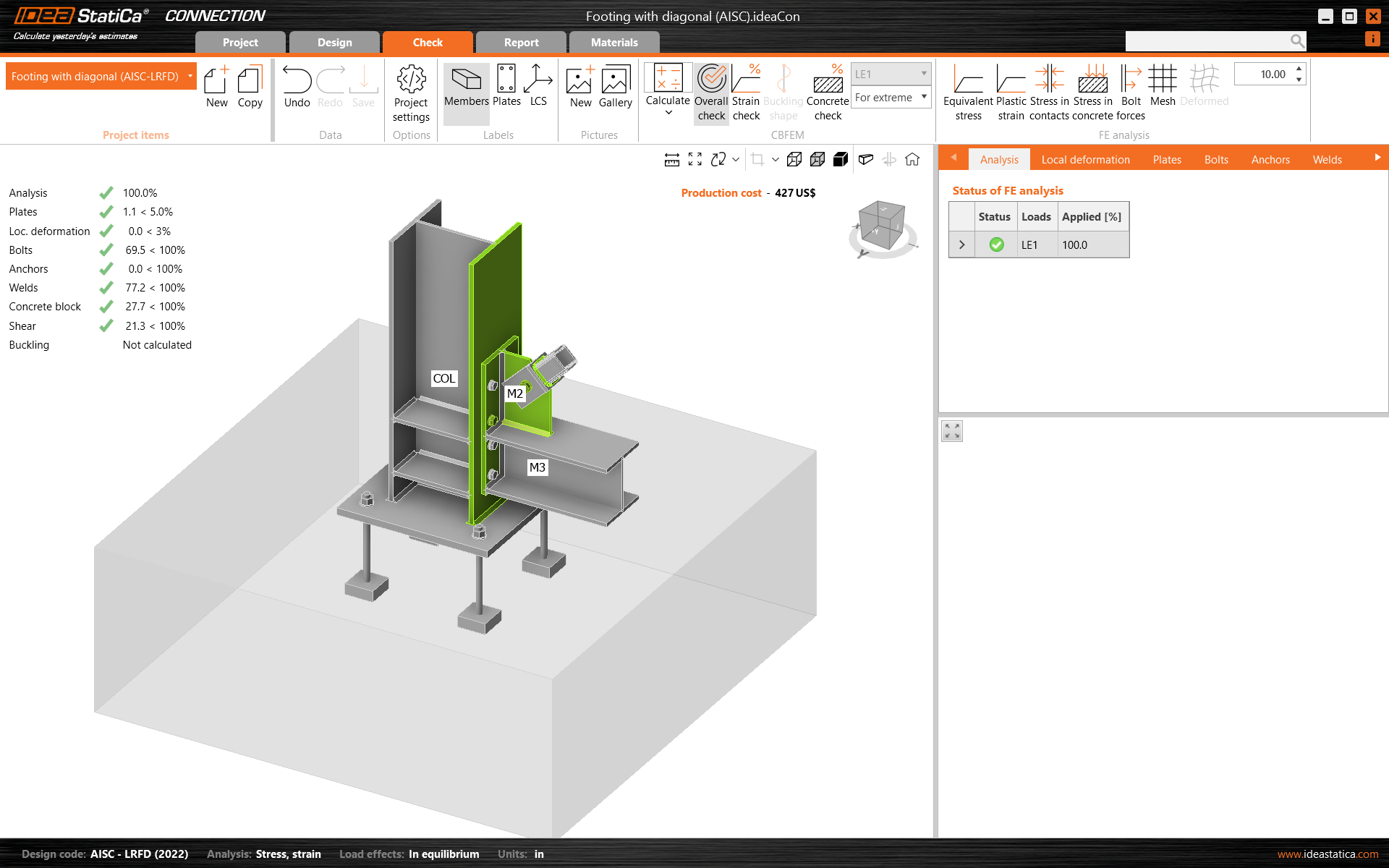
5 Cálculo y verificación
Inicie el análisis haciendo clic en Calcular en la cinta de opciones. El modelo de análisis se genera automáticamente, se realiza el cálculo basado en CBFEM y podemos ver la verificación global mostrada junto con los valores fundamentales de los resultados de la verificación.
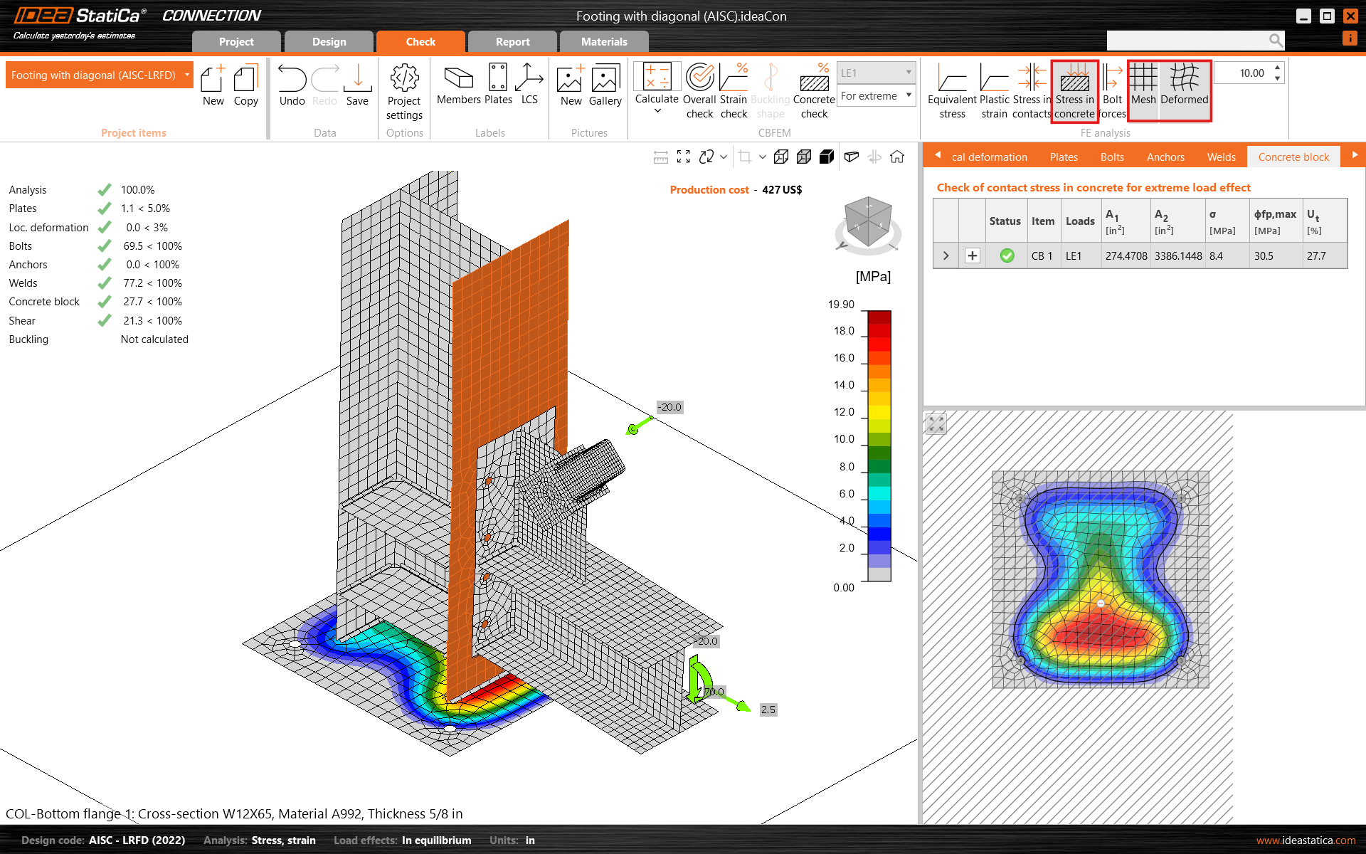
Vaya a la pestaña de visualización Verificación, y active Tensión en el hormigón y Malla desde la cinta de opciones para obtener una imagen completa de lo que ocurre en la junta. Abra la pestaña Bloque de hormigón para ver los resultados detallados de este elemento.
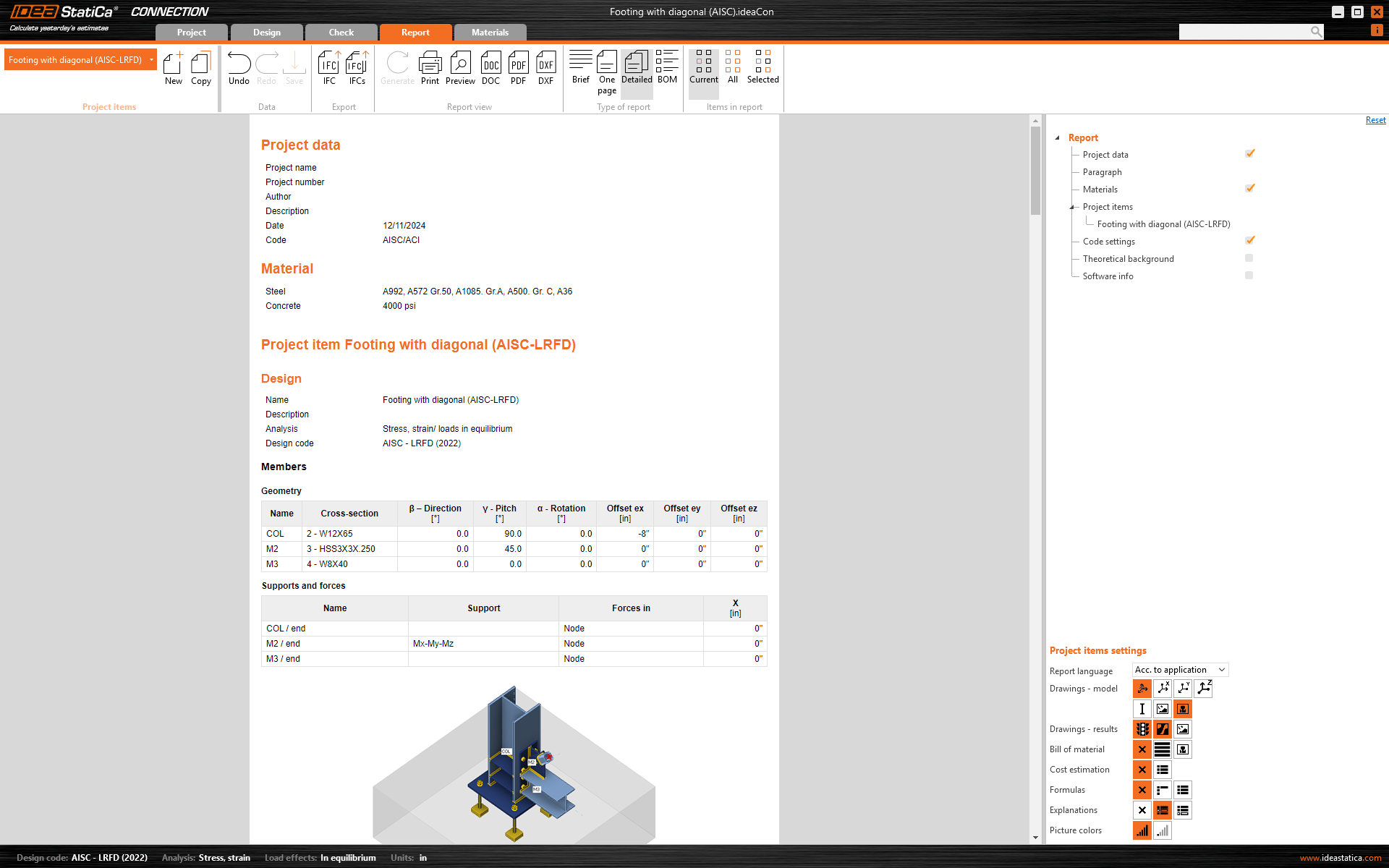
6 Informe
Por último, vaya a la pestaña Informe. IDEA StatiCa ofrece un informe totalmente personalizable para imprimir o guardar en formato editable.
Ha diseñado, optimizado y realizado la verificación normativa de una unión de acero estructural según AISC.