Diseño de capacidad de unión de acero (EN)
1 Nuevo proyecto
Inicie IDEA StatiCa (descargue la versión más reciente) y descargue y abra el archivo de proyecto fuente. El diseño de la junta está terminado y está preparado para el análisis estándar de Tensión/Deformación.
Nota: Otros diseños de uniones sísmicas se pueden encontrar en el conjunto Sísmico de plantillas en la columna Definir Geometría en el asistente de unión desde la versión 25.0.

2 Cálculo y verificación
Inicie el análisis de tensión/deformación con el botón Calcular en la cinta. El modelo de análisis se genera automáticamente, se realiza el cálculo y puede ver los resultados generales de la verificación en la esquina superior izquierda de la escena.

Puede ver que, según el análisis de tensión/deformación, la junta está bien diseñada y ha superado todas las verificaciones.
Para conservar estos resultados, copie este elemento de proyecto.

3 Verificación de capacidad
En el nuevo elemento de proyecto (CON2), cambie el tipo de análisis a CD – Diseño de capacidad.

El elemento disipativo debe ser seleccionado. Se puede añadir mediante el comando de la cinta superior o haciendo clic derecho con el ratón en el árbol de la escena.

Se debe elegir como elemento disipativo un elemento o una placa donde se espera que se produzca una rótula plástica. El factor de sobreresistencia del material y el factor de endurecimiento por deformación se aplican al elemento elegido. En este ejemplo, seleccione el elemento IPE360 como elemento disipativo y confirme la selección con la barra espaciadora/tecla enter/clic derecho o usando el icono de verificación.

En las propiedades del elemento IPE360, ajuste los parámetros:
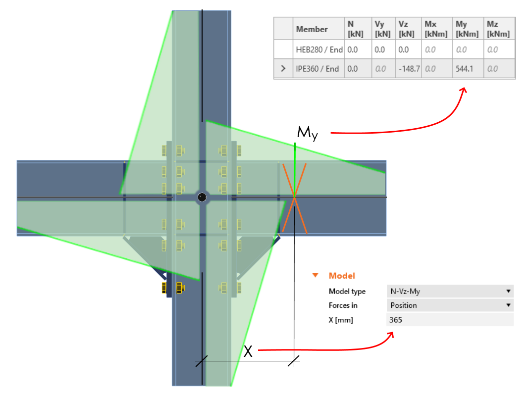
- Establezca el Tipo de modelo en N-Vz-My, porque la unión solo puede resistir el momento flector en el plano vertical y el giro alrededor del eje menor de la viga debe estar restringido. Más información en Cómo modelar una unión de un solo tornillo (Tipo de modelo)
- Cambie el parámetro Fuerzas en a Posición, porque así se puede definir la posición exacta de la fuerza actuante. La posición de la rótula plástica es similar a la posición de la fuerza actuante: X = 365 mm. Más información en Cómo definir la posición de carga correcta (Fuerzas en)

¿Cómo conocer la posición correcta de la rótula plástica? El ingeniero debe decidir dónde se producirá. Normalmente, la rótula plástica se determina en la viga. En este ejemplo, se producirá justo detrás de la cara del último rigidizador. Es conveniente leer la posición desde la aplicación (vista de estructura alámbrica).

En el siguiente paso, se deben definir los efectos de carga. Las cargas para el análisis sísmico dependen de la normativa (el factor de sobreresistencia del material, el factor de endurecimiento por deformación) y también están influenciadas por el límite elástico, las características geométricas de la sección transversal, etc.
Las cargas para este ejemplo se calcularon mediante este procedimiento:
\[M_{\textrm{Ed}} = \gamma_{\textrm{sh}} \cdot f_{\textrm{y,ov}} \cdot W_{\textrm{p}l} = 1.2 \cdot 443.75 \cdot 10^6 \cdot 1.0218 \cdot 10^{-3} = 544.12 \, \textrm{kNm} \]
\( \gamma_{\textrm{sh}} = 1.2 \)
\( f_\textrm{y} = 355 \, \textrm{MPa} \)
\( f_{\textrm{y,ov}} = f_\textrm{y} \cdot \gamma_{\textrm{ov}} = 355 \cdot 1.25 = 443.75\, \textrm{MPa} \)
\( \gamma_{\textrm{ov}} = 1.25 \)
\( W_{\textrm{pl,IPE360}} = 1.0218 \cdot 10^6 \, \textrm{mm}^3 \)
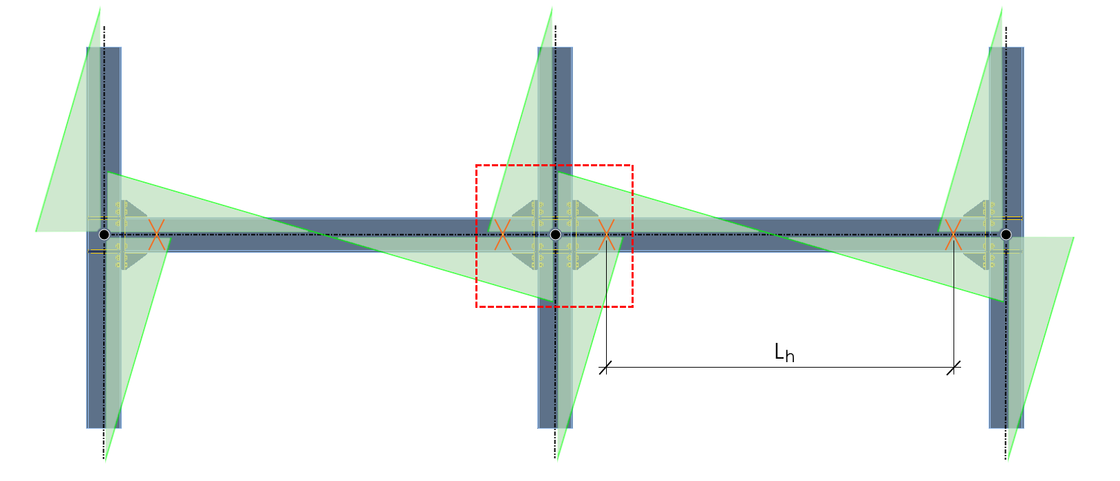
\[ V_{\textrm{Ed}} = \frac{2 \cdot M_{\textrm{Ed}}}{L_{h}} = 2 \cdot \frac{544.12}{7.32} = 148.67 \, \textrm{kN} \]
\(L_{h} = 7.32 \, \textrm{m} \, -\) distancia entre rótulas plásticas en la viga
Añada la fuerza cortante y el momento flector calculados como un nuevo efecto de carga (EC).

La fuerza cortante y el momento flector deben tener los signos apropiados para que el momento flector disminuya en la viga en la dirección que se aleja del nodo.
Copie este EC y cambie la orientación de las fuerzas actuantes para que el segundo EC actúe en la dirección opuesta.

Ahora el análisis de capacidad puede iniciarse con el comando Calcular.

Puede ver en los resultados que la junta no superó la verificación normativa. Se requieren algunos cambios en el diseño.
Aumente el espesor de la placa de testa a 25 mm para evitar que colapse.

Para aumentar la capacidad de carga del pilar, añada un duplicador a su alma (añada la operación de fabricación Placa de rigidización).

El duplicador se suelda mediante soldaduras a tope al alma del pilar; también es necesario definir la soldadura a los patines.

Las otras cuatro soldaduras deben añadirse para soldar los duplicadores en ambos lados del pilar a ambos patines.


Los rigidizadores en el alma del pilar deben cortarse y soldarse a los duplicadores mediante la operación de fabricación Corte de la placa.

Repita el corte de la placa para conectar los cuatro rigidizadores a los duplicadores.

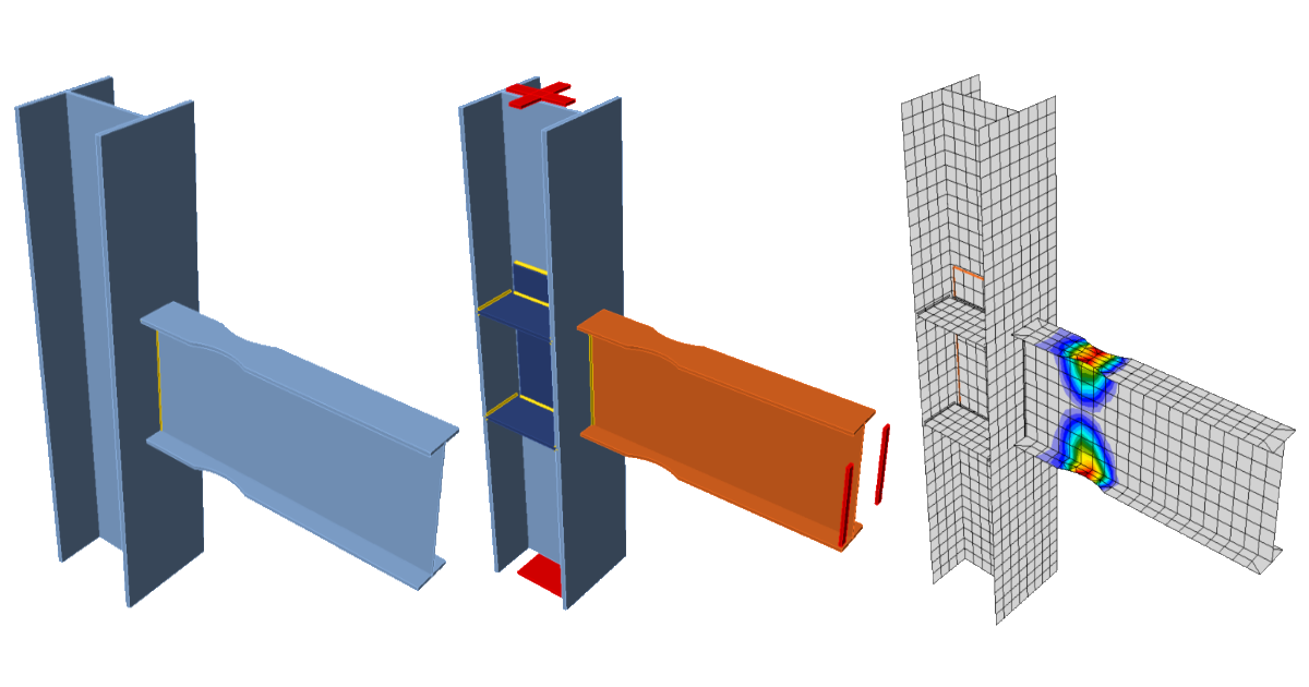
Todas las acciones de diseño están realizadas, ejecute Calcular en la pestaña Verificación. Puede ver que todos los componentes (como soldaduras y tornillos) superaron la verificación normativa. La deformación plástica de las placas del elemento disipativo no influye en los resultados generales.

La aparición de la rótula plástica puede explorarse si se activa la Deformación plástica.

La rótula plástica apareció en la ubicación esperada, y esta junta superó las verificaciones requeridas por el diseño de capacidad.
Para una mejor comprensión de los resultados, consulte el Trasfondo Teórico.
4 Informe
Por último, puede revisar el Informe. IDEA StatiCa ofrece un informe totalmente personalizable para imprimir o guardar en formato editable.

Ha realizado una verificación de diseño de capacidad de una junta de acero estructural según el Eurocódigo (EN).