Análisis de pandeo de una unión de acero (AISC)
1 Nuevo proyecto
Lancemos la aplicación IDEA StatiCa Connection (descargue la versión más reciente). Cree un nuevo proyecto seleccionando la plantilla más cercana al diseño requerido y rellene el nombre y la descripción del proyecto. Tras elegir las propiedades requeridas, confirme con Create project.
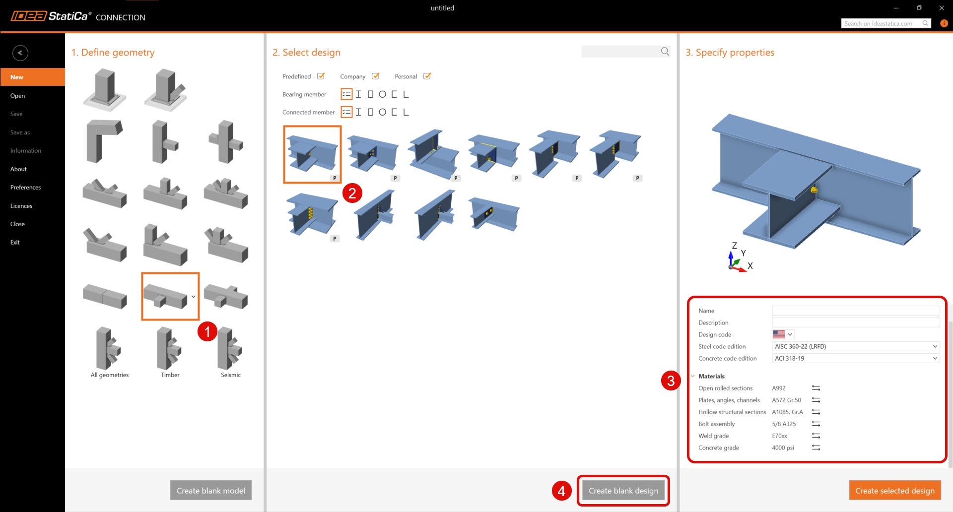
Dado que utilizamos el código AISC, establezca las unidades imperiales (consulte Cómo cambiar el sistema de unidades).
2 Geometría
Comience con la modificación de la geometría de la junta. Haga clic con el botón derecho en el alma de la viga continua para abrir el menú contextual con todas las acciones disponibles para las vigas. Utilice el botón Plus para añadir una nueva sección transversal.
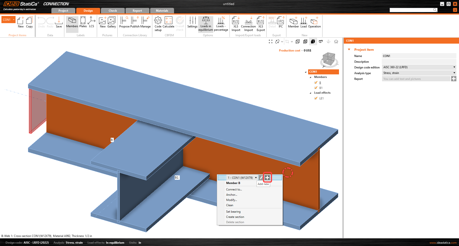
Elija el perfil I, la categoría W(AISC 15.0) y la sección transversal W8X31.
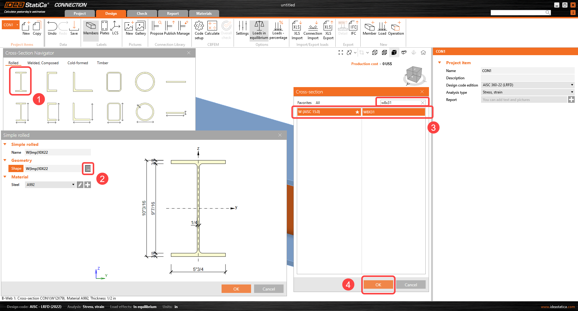
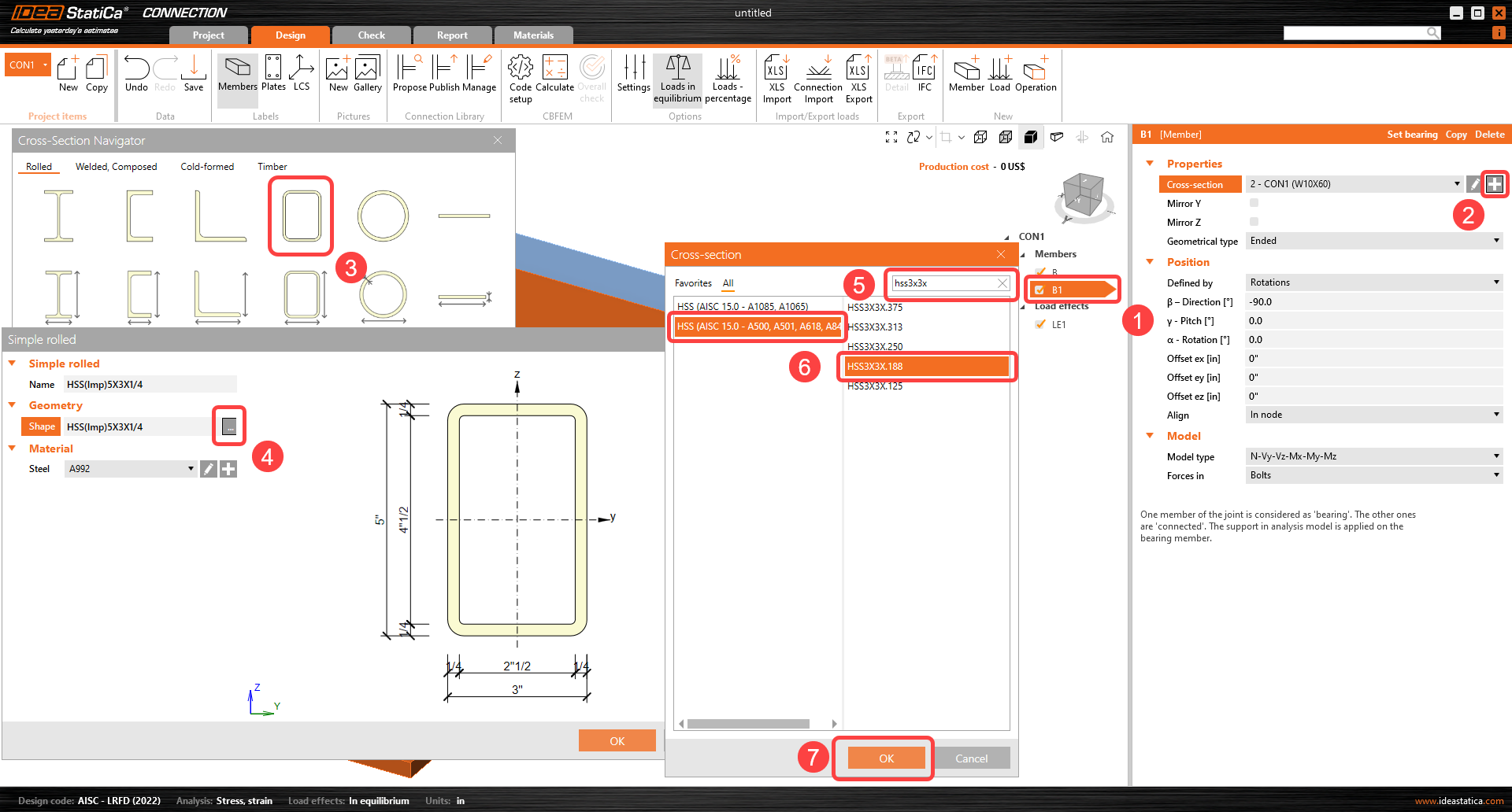
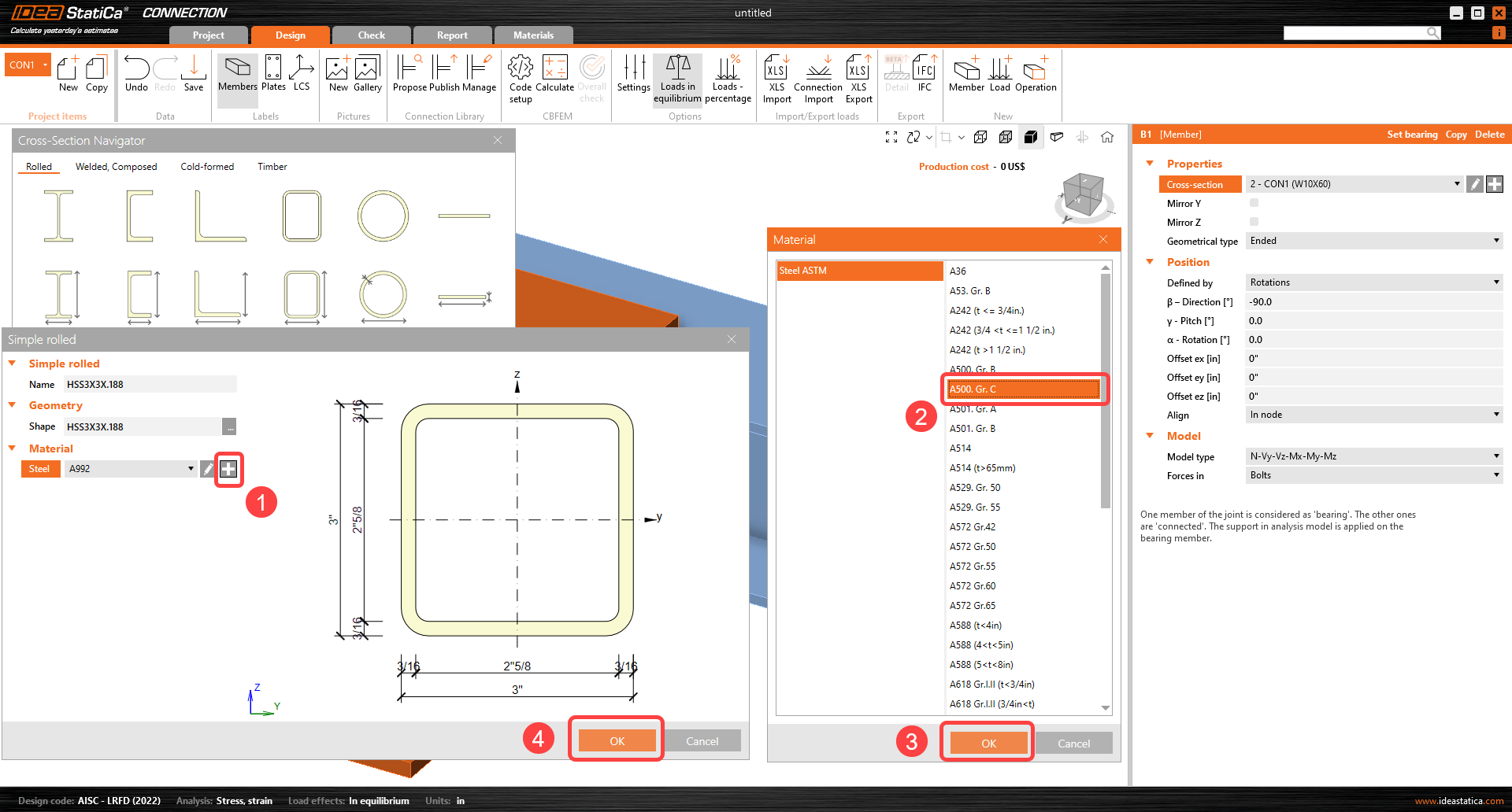
Continúe con el cambio de sección transversal en el elemento perpendicular. Seleccione el elemento B1 en el árbol de entidades y haga clic en el icono de más para la sección transversal. Seleccione la sección transversal HSS3X3X.188 con la biblioteca correcta que se muestra a continuación. Asegúrese de que la nueva sección transversal HSS también tenga el material correcto seleccionado.
Ahora puede ajustar las propiedades de la viga B1 con sección transversal cuadrada. Siga la imagen a continuación.
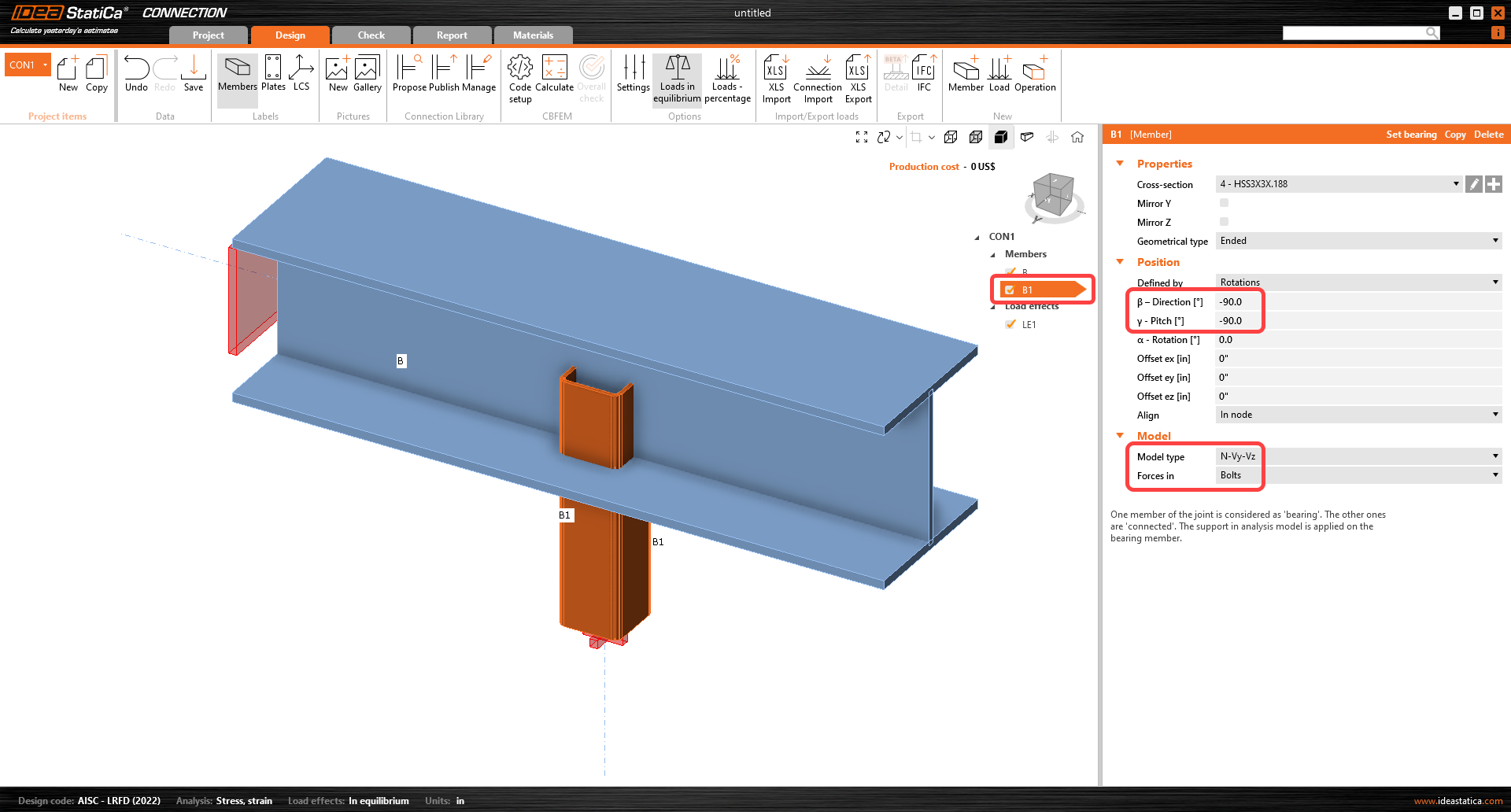
Lea más sobre el tipo de modelo y las fuerzas en los parámetros en los artículos Cómo modelar una unión de un solo perno (tipo de modelo) y Cómo definir la posición correcta de la carga (Fuerzas en).
3 Efectos de carga
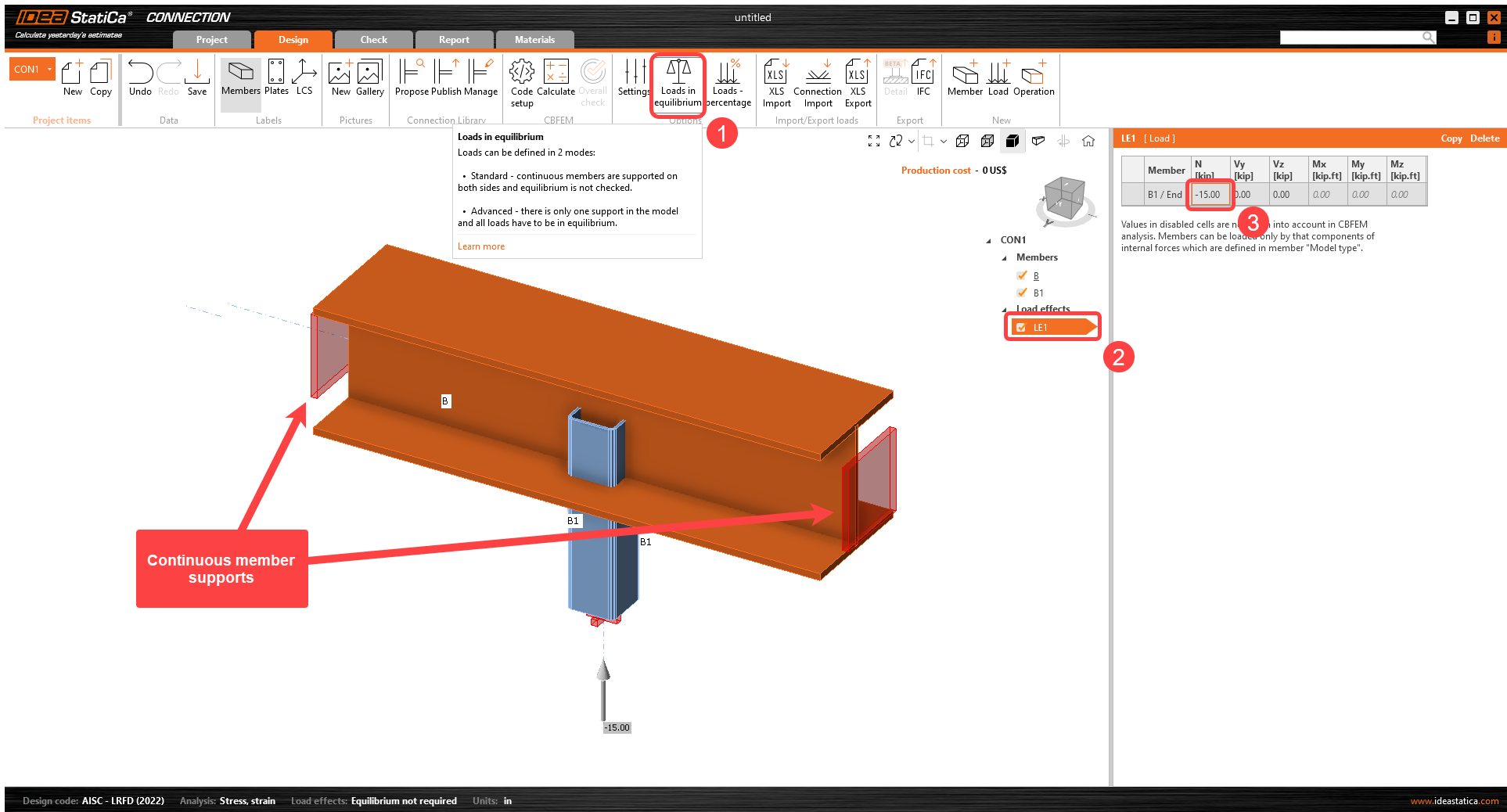
Continuemos con los efectos de carga. Desactive Cargas en equilibrio en la cinta superior. Al desactivar Cargas en equilibrio, el elemento portante continuo B queda apoyado en ambos extremos y las cargas no se definen en el elemento portante (la tabla de fuerzas no equilibradas se elimina y no se verifica). Introduzca la fuerza normal de –15 kip en la pestaña del elemento B1.
4 Diseño
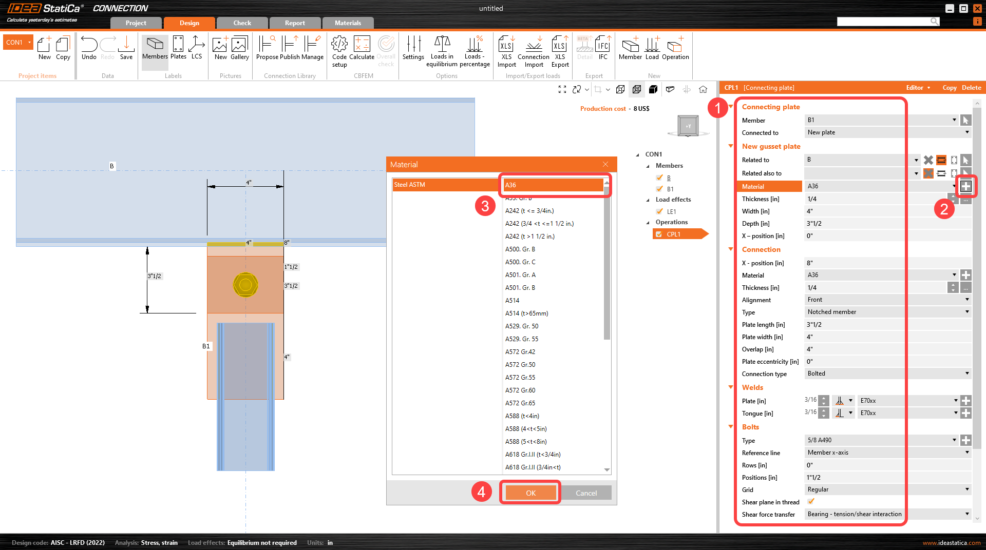
Ahora defina la operación de fabricación. Haga clic en el icono Operación en la cinta superior para abrir la ventana de operaciones de fabricación. De las operaciones disponibles, elija la operación Connecting plate y proceda con la selección del conjunto de pernos deseado, A490 5/8.

Ahora defina las propiedades de la placa de conexión. Siga los valores de la imagen a continuación.
5 Cálculo y verificación
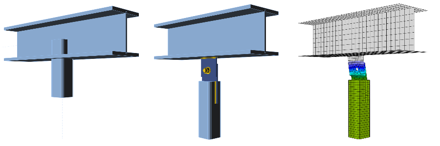
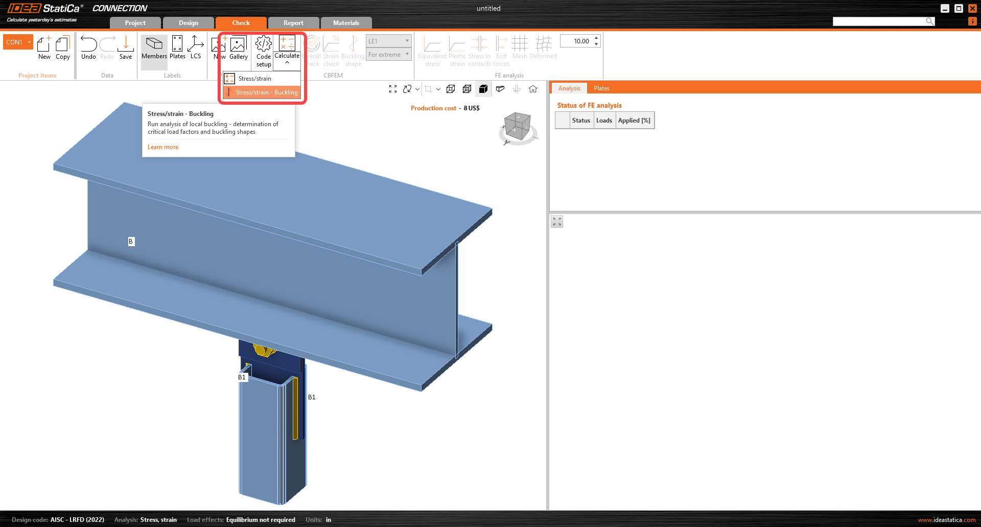
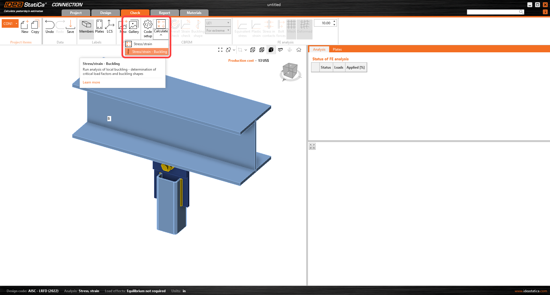
Ahora puede cambiar a la pestaña Check en la parte superior de la cinta y luego iniciar el cálculo del Análisis de pandeo bajo el botón de comando Calculation.
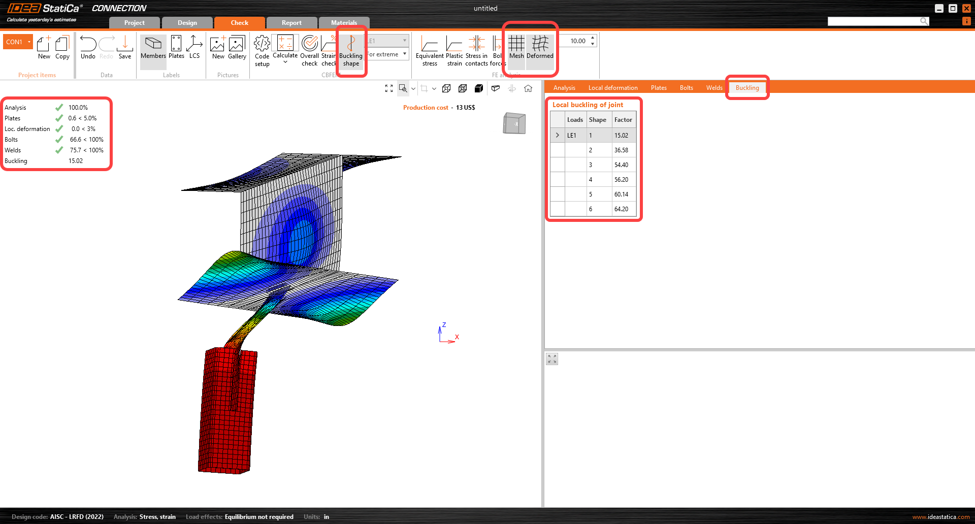
Cuando el análisis haya finalizado, active la vista Buckling shape, Mesh y Deformed. En la pestaña Buckling se proporciona una tabla de factores críticos de pandeo.
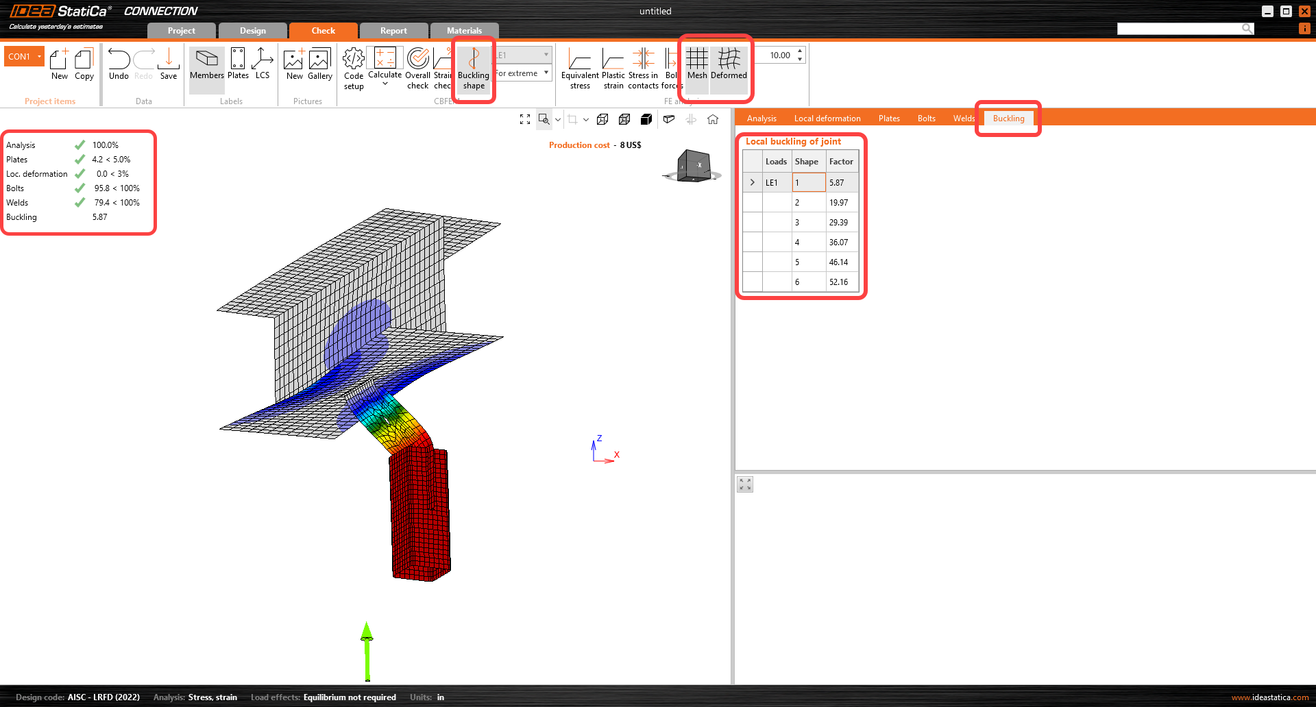
Al hacer clic en cada fila de la pestaña de factores críticos de pandeo, puede explorar las formas deformadas en la ventana 3D y analizarlas visualmente. El factor crítico de pandeo puede compararse con los requisitos normativos.
¿Cómo interpretar los resultados de pandeo?
Para comprender los resultados del análisis, lea los documentos recomendados, como el artículo Fundamento teórico o Análisis de pandeo según AISC.
Al observar la forma deformada y los factores de pandeo, identifique dónde se produce el pandeo:
- Pandeo global: afecta a la estabilidad de la junta
- Pandeo local: no afecta a la estabilidad de la junta, pero influye en las placas de otras partes de la unión
Generalmente, el pandeo puede considerarse seguro cuando los valores del factor crítico de pandeo son superiores a 13 para el pandeo global y a 3 para el pandeo local. Dado que este es un caso de pandeo global y el factor de pandeo es inferior a 13, las recomendaciones son las siguientes:
- Refuerce la unión y recalcule el análisis de pandeo para asegurarse de que el factor crítico de pandeo sea superior a 13,
- o utilice un análisis o enfoque diferente para garantizar que el pandeo no sea peligroso para la unión diseñada.
6 Reforzar la unión
Vuelva a la pestaña Design y cambie las siguientes entradas en la operación CPL1:
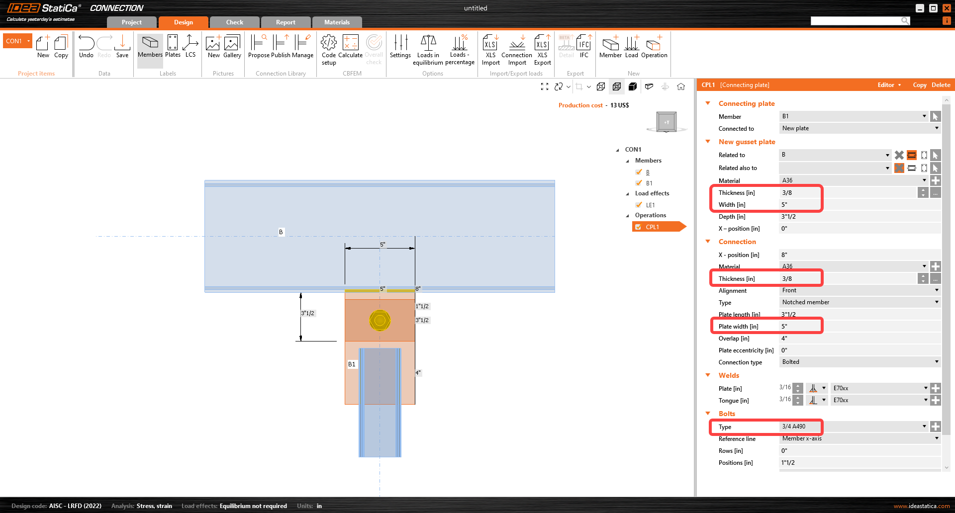
Vaya a la pestaña Check y haga clic en el menú desplegable Calculate y seleccione Stress/strain - Buckling.
Revise las formas y los factores de pandeo. El factor del primer modo de pandeo es ahora superior a los requisitos normativos mínimos.
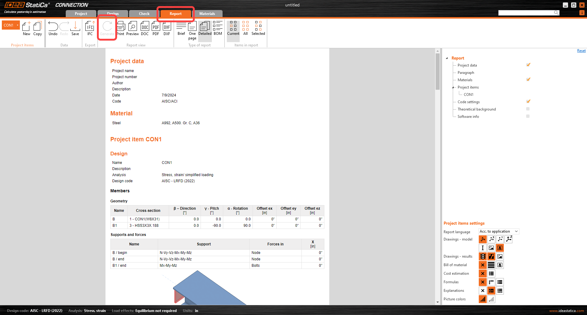
7 Informe
Por último, vaya a la pestaña Report . IDEA StatiCa ofrece un informe totalmente personalizable para imprimir o guardar en formato editable.
Ha diseñado, optimizado y realizado la verificación normativa de una junta de acero estructural según AISC.