


1. What is IDEA StatiCa Detail 2D used for?
IDEA StatiCa Detail 2D is a specialised design and verification software for local regions of concrete structures. It does not replace the global structural analysis of the overall structure. In other words, the design of the required reinforcing steel is typically performed in a global beam, slab, or shell model.
Typical applications include:
- Discontinuity regions (D-regions), where the Bernoulli hypothesis of plane sections remaining plane is no longer valid. Examples include support regions, openings, notches, frame corners, haunches, abrupt changes in geometry, and local force introduction areas.
- Design and optimisation of reinforcement layouts. The software identifies which reinforcement bars are effective in terms of load-bearing capacity, crack control, and anchorage. Reinforcement subjected to only minor stresses can subsequently be assessed by engineering judgement and, where appropriate, reduced. Eliminating such passive reinforcement improves both constructability and the economic efficiency of the reinforcement arrangement.
- Detailed investigation of cracking behaviour. In addition to crack widths, stresses and strains in both concrete and reinforcement can be evaluated. This is particularly useful at re-entrant corners, in haunches, and in areas of concentrated load introduction. Stress concentrations may also indicate an increased likelihood of concrete spalling.
- Verification and interpretation using strut-and-tie models. Strut-and-tie models are often used to better illustrate the stress flow in the ultimate limit state (ULS). However, developing such models frequently involves uncertainties, for example in defining the inclination and width of struts. Detail 2D enables the generation of a strut-and-tie model that allows structural engineers to validate finite element results and provide an additional verification for the independent structural review.
Tip 1
Only those regions that present a particular structural challenge should be modelled in Detail 2D rather than the entire structural system. This results in dedicated local models that specifically represent the critical regions under investigation.
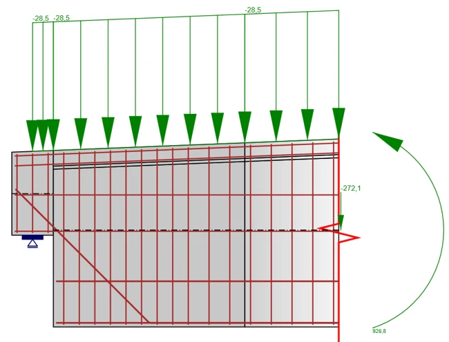
Figure: Analysis of a local support region
Tip 2
There is no universal recipe for successful finite element modelling of a structural member. The experience and engineering judgement of the structural engineer are decisive. As a general rule, the model should be kept as simple as possible in order to facilitate a clear understanding of the stress distribution.
Tip 3
If singularities and unrealistic reinforcement peaks occur in a linear shell analysis, a local nonlinear detail model can help to identify and evaluate the underlying cause more accurately.
2. How are geometry and reinforcement defined?
Simple geometries can be defined directly using coordinates. Repetitive structural elements and reinforcement groups can be copied and replicated. For more complex shapes, DXF import is recommended.
Only the structurally relevant geometry should be imported. Very small recesses, fillets, or construction details increase modelling effort without necessarily improving the representation of the actual structural behaviour.
In addition, predefined templates are available for common applications.
Tip 4
Use the multi-selection function to modify the properties of multiple reinforcement groups—such as bar diameter, material grade, or anchorage type—in a single step. This accelerates parametric studies and reduces the risk of inconsistent input data.
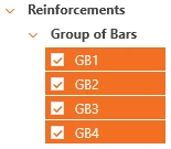
Figure: Multi-selection of reinforcement groups
3. How can supports be modelled realistically?
In IDEA StatiCa Detail 2D, point supports and line supports can be defined and adjusted with respect to stiffness and translational restraint.
For realistic boundary conditions, the support representation must correspond to the actual bearing and contact area. Excessively small support widths lead to artificial stress concentrations. Spring stiffnesses can be used to model flexible supports. For line supports, uplift effects can also be considered.
Tip 5
For foundations, it is advisable to model the soil support using springs. Compression-only springs or contact conditions without tensile force transfer allow the analysis of opening joints.
Point supports should always be assigned a realistic bearing width to avoid stress concentrations and subsequent numerical instability. Experience has shown that line supports generally provide more robust numerical behaviour than point supports and should therefore be preferred whenever possible.
4. What types of loads can be applied?
The following load types can be defined in Detail 2D:
- Point loads for modelling concentrated forces acting at specific locations.
- Line loads for modelling constant or varying loads acting along a line.
Load positions can be defined flexibly by specifying the corresponding coordinates.
Tip 6
The effective radius of a point load describes the distribution of the load introduction within the 2D model. A very small radius generates correspondingly high local stresses and strains, thereby increasing the likelihood of local failure.
The value should therefore be derived from the actual contact area, such as a bearing plate or the loaded surface of a structural component. Alternatively, concentrated loads may be converted into line loads.
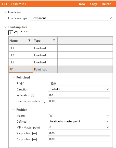
Figure: Definition of a point load and its effective radius
Tip 7
Concentrated moments can be represented by a combination of compressive line loads and tensile forces carried by reinforcement. The applied force spacing should correspond to the internal lever arm. The compression force should be introduced through a realistic compression zone, while the tensile force must be resisted by suitable and adequately anchored reinforcement.
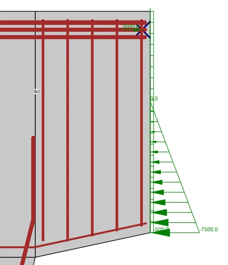
Figure: Decomposition of a bending moment into concentrated forces
5. How are actions combined?
IDEA StatiCa Detail 2D performs nonlinear analysis considering the material behaviour of both concrete and reinforcement. Unlike linear analysis, the software cannot automatically determine favourable or unfavourable internal force effects.
Consequently, different load combinations must be defined manually by the user.
Tip 8
Determine the governing load combinations from the global analysis software and apply them in Detail 2D.
Typically, the following combinations are considered:
- MaxM: Maximum bending moment together with the corresponding internal forces.
- MaxV: Maximum shear force together with the corresponding internal forces.
- MaxN / MinN: Maximum or minimum axial force together with the corresponding internal forces.
6. Which workflow leads quickly to a suitable reinforcement layout?
The required reinforcement can be determined from the global structural model or from a simplified strut-and-tie model, for example in the case of a D-region. Based on this information, a reinforcement sketch can be prepared and used as the basis for reinforcement input in Detail 2D.
After the initial analysis, failed verifications and heavily stressed regions should be investigated in a targeted manner. Where verification requirements are not met, reinforcement can be increased in the governing regions.
If utilisation levels are low, the reinforcement quantity may be reduced step by step. However, reinforcement bars should not be removed solely because of low calculated stress levels. Minimum reinforcement requirements and the detailing functions of the reinforcement within the analysed region must also be considered.
Tip 9
For preliminary design iterations, a coarser mesh or a larger mesh factor, for example 3 or 4, can be used to save calculation time. The coarse model is intended for concept development and optimisation rather than final documentation.
Once the model is stable and the results appear plausible, the final design should be carried out using the standard mesh factor of 1.0. A mesh size smaller than 1.0 is generally not required, as the software has been validated for this mesh density.
Tip 10
For many reinforced concrete details, it is efficient to begin with crack control design, as this is often the governing criterion. Regardless of the chosen sequence, all ultimate limit state verifications must still be performed in full; the order is simply a matter of an efficient workflow.
7. What causes numerical instability?
A non-converging analysis may indicate either an unsuitable model or a structural component that genuinely lacks sufficient load-bearing capacity.
Common causes include:
- Stress concentrations resulting from unrealistically small or point-supported bearings.
- Abrupt geometric changes.
- Large unreinforced tension zones.
- Loads exceeding the structural resistance.
Realistic support widths, an appropriate mesh, the use of line supports, and a suitable distribution of applied loads often improve numerical stability.
Tip 11
An incorrect model produces incorrect results. Therefore, model your structure using sound engineering judgement and critically review all modelling assumptions.
Avoid unnecessary modelling complexity and verify the results using simplified hand calculations. These provide an important basis for plausibility checking. In addition, verify whether compression struts, tension ties, crack patterns, and actively utilised reinforcement correspond to the expected structural behaviour.
8. Can material properties be modified?
Material properties and stress-strain relationships can be adjusted to suit project-specific requirements.
This enables investigations of existing concrete, fibre-reinforced concrete, or special concrete types, such as proprietary repair mortars from Pagel. Custom material properties can also be defined for reinforcing steel and prestressing steel.
The bond characteristics between concrete and reinforcement may likewise be modified, for example when assessing existing structures with smooth reinforcement bars.
Such modifications must be technically justified and clearly documented in the calculation report.
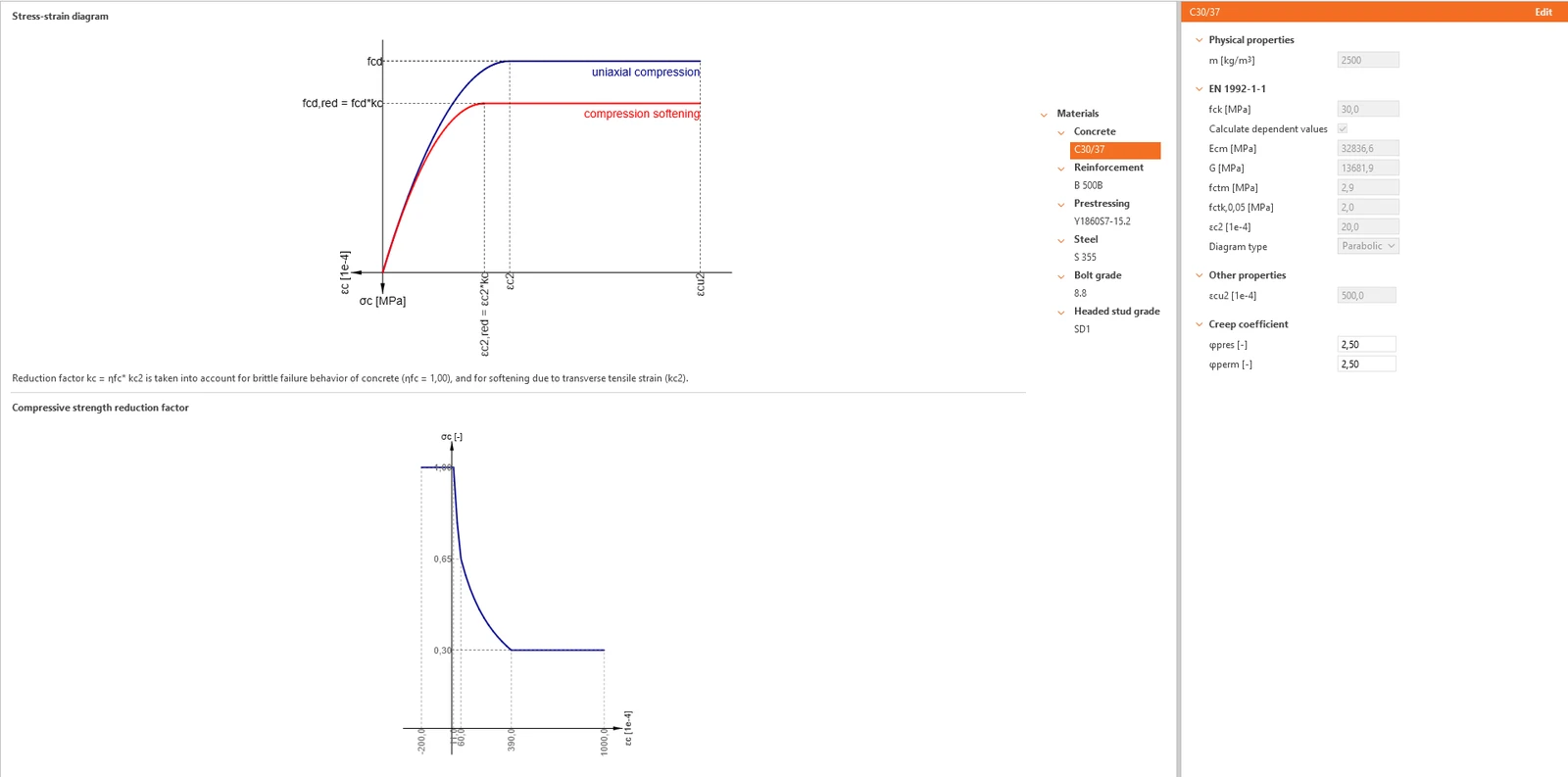
Figure: Modification of material properties
9. How can modelling be accelerated?
For recurring tasks, the use of templates is recommended.
IDEA StatiCa Detail 2D provides a wide range of templates for various applications, such as roof trusses, frame joints, pile caps, and many other structural configurations. These templates can be used as a starting point and adapted to the specific requirements of a project.
As a result, repetitive tasks can be completed significantly faster and more efficiently.
Tip 12
Users can also create and reuse their own templates. This is a particularly efficient approach for standardised precast concrete elements that differ only in dimensions or similar parameters.
Before saving a model as a template, boundary conditions, naming conventions, material properties, and report settings should be cleaned up. This prevents project-specific assumptions from unintentionally being carried over into future calculations.
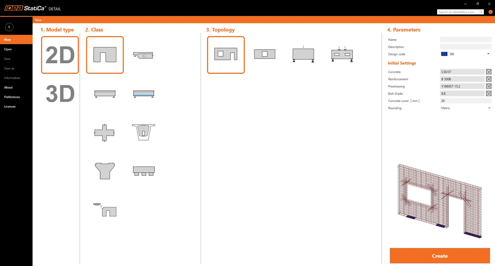
Figure: Selection of predefined templates
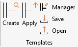
Figure: Saving and managing custom templates
10. How can custom comments be added to the report?
To customise the report, it is recommended to export the calculation report as a Word document. Additional comments, explanations, and project-specific notes can then be incorporated. Layout, formatting, and further content can also be edited according to the specific project requirements.