Legătură BIM RFEM/RSTAB pentru proiectarea îmbinărilor metalice (EN)
Cum se activează legătura
- Descărcați și instalați cea mai recentă versiune de IDEA StatiCa
- Asigurați-vă că utilizați o versiune compatibilă a soluției dvs. de calcul structural
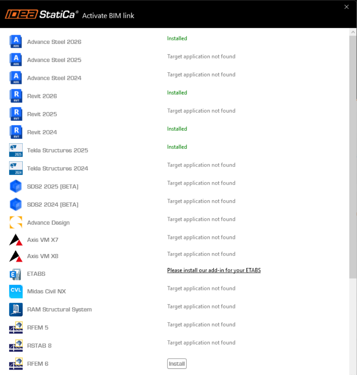
IDEA StatiCa integrează legăturile BIM în soluțiile dvs. de calcul structural în timpul instalării. Puteți verifica starea și activa mai multe legături BIM pentru software-ul instalat ulterior în programul de instalare a legăturilor BIM.
Rețineți că unele soluții de calcul structural necesită pași suplimentari pentru a activa complet legătura BIM cu IDEA StatiCa.
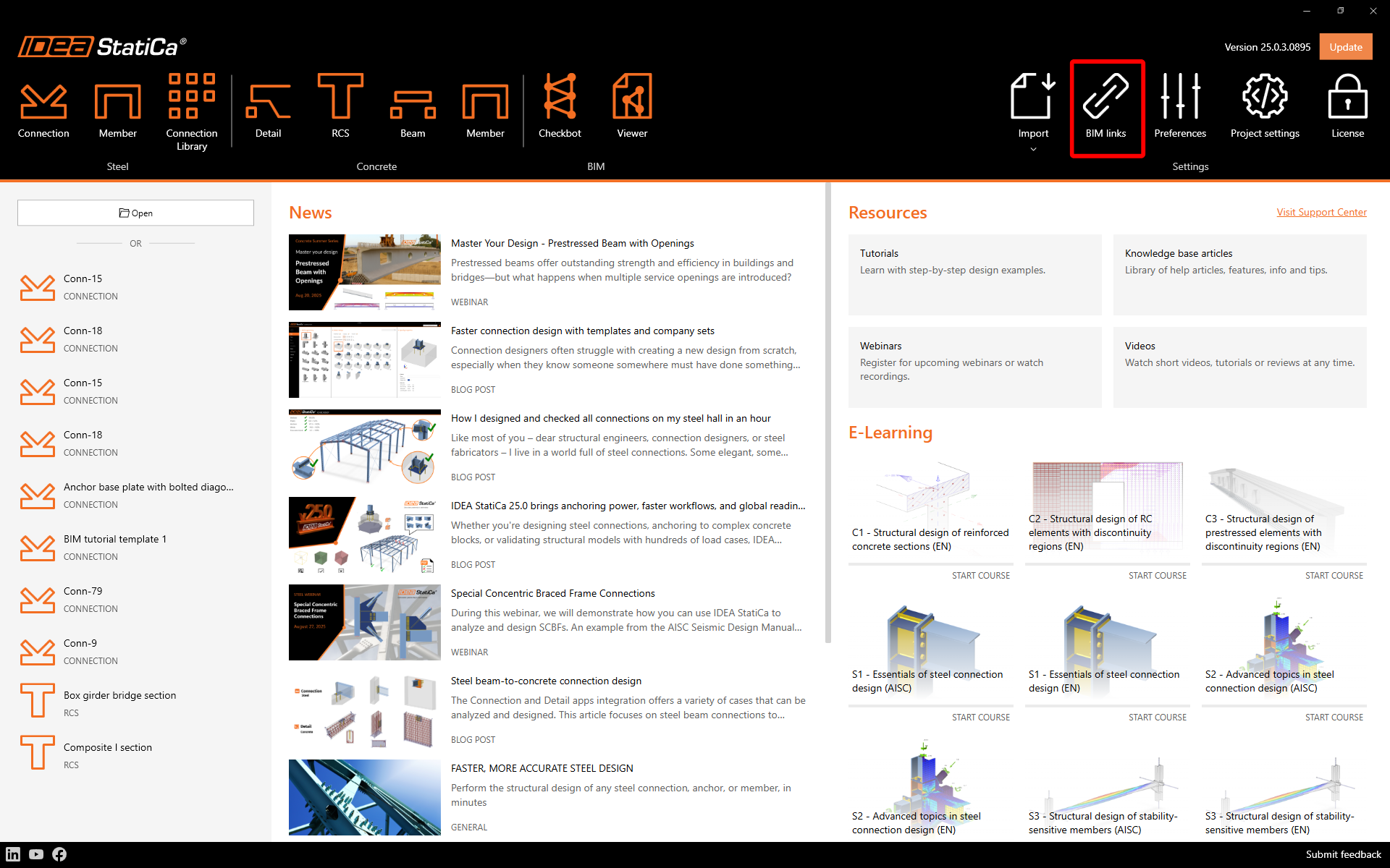
Deschideți IDEA StatiCa și navigați la fila BIM și deschideți programul de instalare a legăturilor BIM (Activați legătura BIM...).
Este posibil să apară o notificare „Doriți să permiteți acestei aplicații să facă modificări pe dispozitivul dvs.?", caz în care confirmați cu butonul Da.
Cum se activează legătura - RFEM 5 și RSTAB 8
Legătura BIM pentru software-ul selectat (dacă este găsit) este instalată. Ecranul vă indică, de asemenea, starea altor legături BIM care ar putea fi deja instalate. Dacă este necesar, faceți clic pe Instalare pentru a activa orice legătură BIM.
Cum se activează legătura - RFEM 6 și RSTAB 9
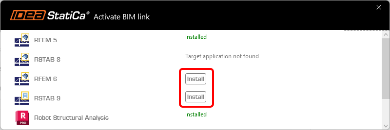
În programul de instalare a legăturilor BIM, faceți clic pe Instalare pentru a crea o pictogramă de comandă rapidă IDEA StatiCa 2X.X for RFEM 6/IDEA StatiCa 2X.X for RSTAB 9 pe desktop.
Notă: fișierul original se află la calea C:\Program Files\IDEA StatiCa\StatiCa 2X.X\net6.0-windows\IdeaRFEMLink.exe sau IdeaRSTABLink.exe
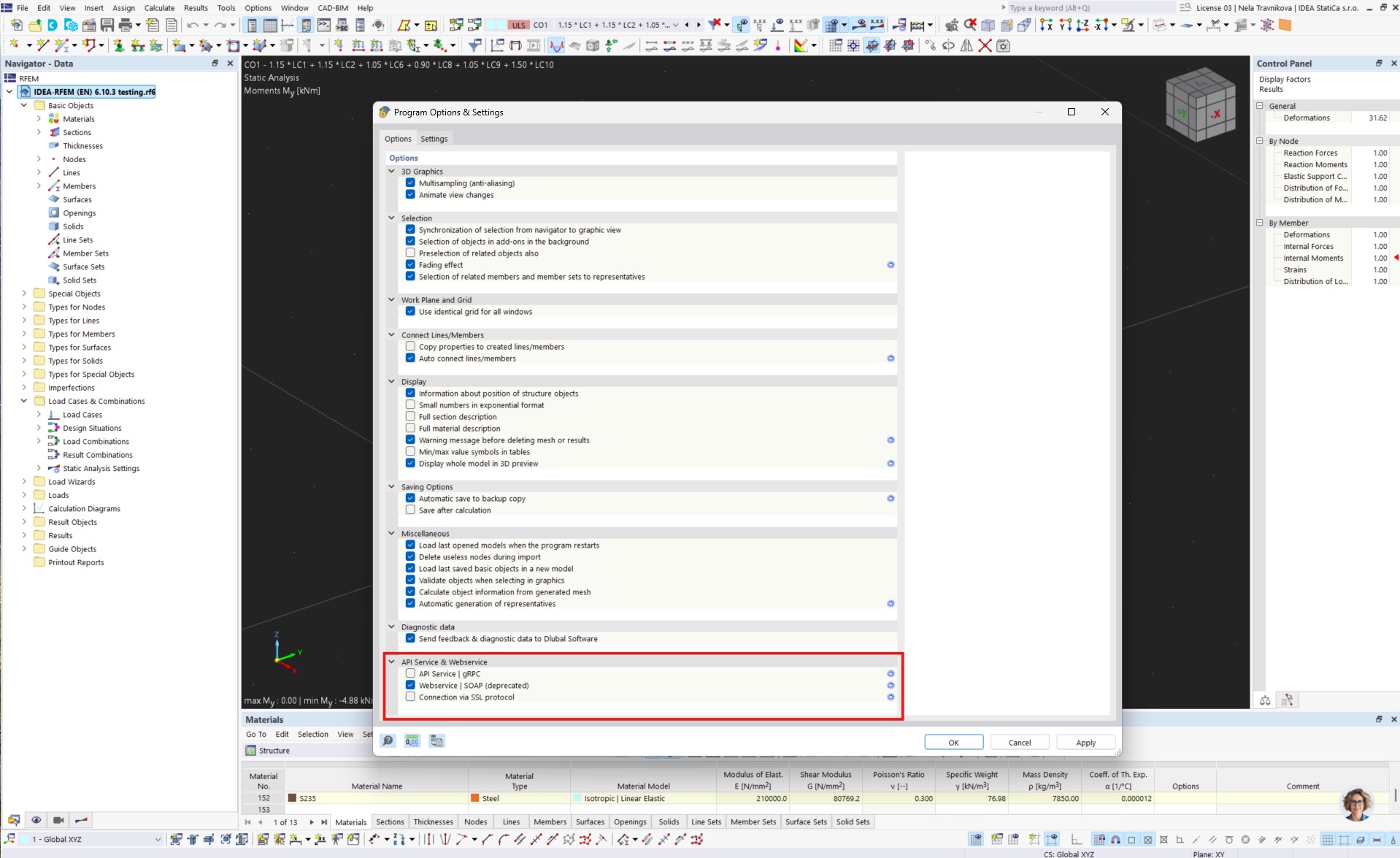
Deschideți RFEM 6/RSTAB 9 și navigați la meniul Opțiuni și Opțiuni program, apoi activați WebService pentru a permite transferul de date.
Cum se utilizează legătura
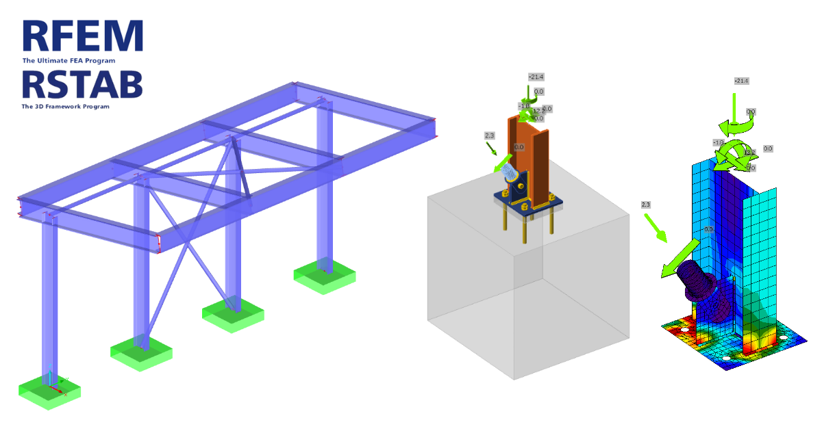
Descărcați proiectul atașat, deschideți-l în RFEM/RSTAB și rulați calculul pentru a obține eforturile interne din structură.
Cum se utilizează legătura - RFEM 5 și RSTAB 8
În meniul panglică, navigați la Module suplimentare și Module externe și IDEA StatiCa Checkbot.

Cum se utilizează legătura - RFEM 6 și RSTAB 9
În RFEM 6/RSTAB 9 nu există o comandă în meniul panglică. În schimb, cu proiectul RFEM 6/RSTAB 9 deschis, mergeți pe desktop și rulați pictograma de comandă rapidă IDEA StatiCa 2X.X for RFEM 6/IDEA StatiCa 2X.X for RSTAB 9.

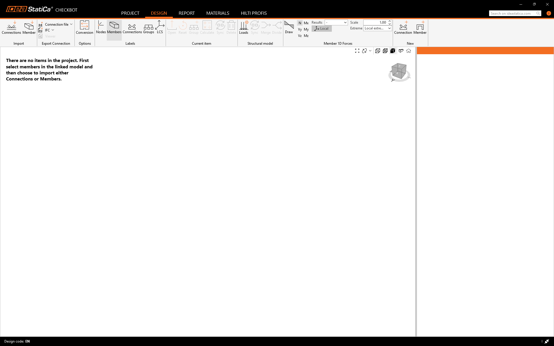
Se deschide aplicația Checkbot, care funcționează ca manager al legăturilor BIM, și puteți începe un proiect nou.
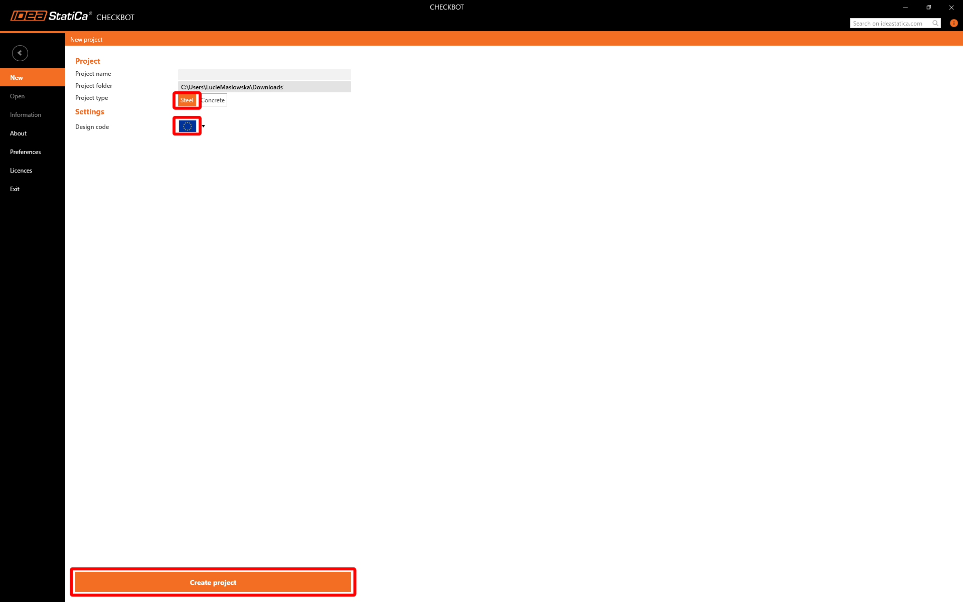
Selectați opțiunea Nou cu tipul de proiect Oțel și codul de proiectare EN. Apoi selectați Creare proiect.
Noul proiect Checkbot este pregătit pentru importul îmbinărilor din RFEM/RSTAB.
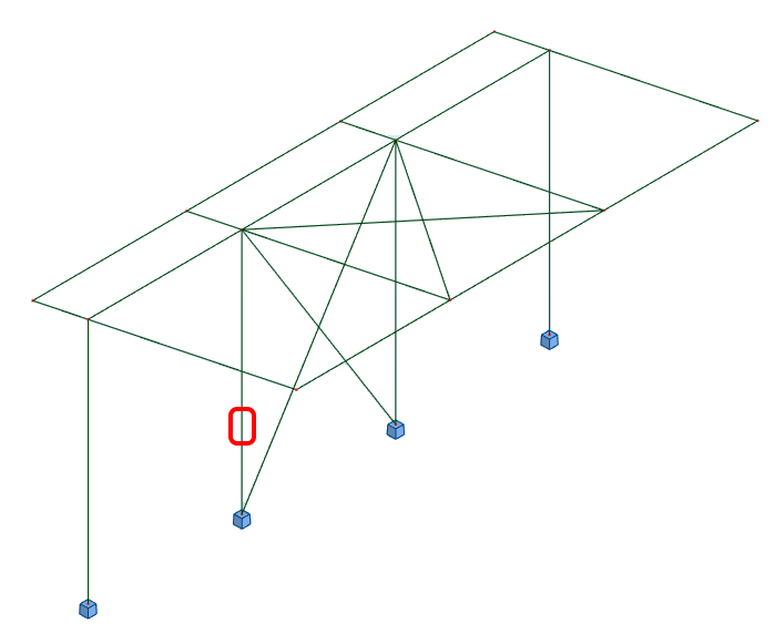
În RFEM/RSTAB, selectați unul dintre stâlpii interiori cu contravântuire, asigurându-vă că selectați și nodul inferior.

Import
Apoi în Checkbot selectați Connections.
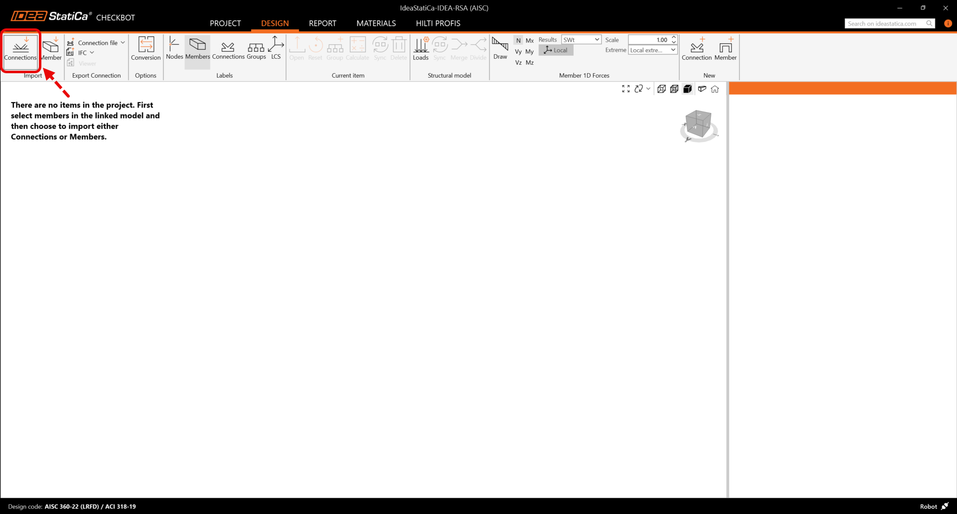
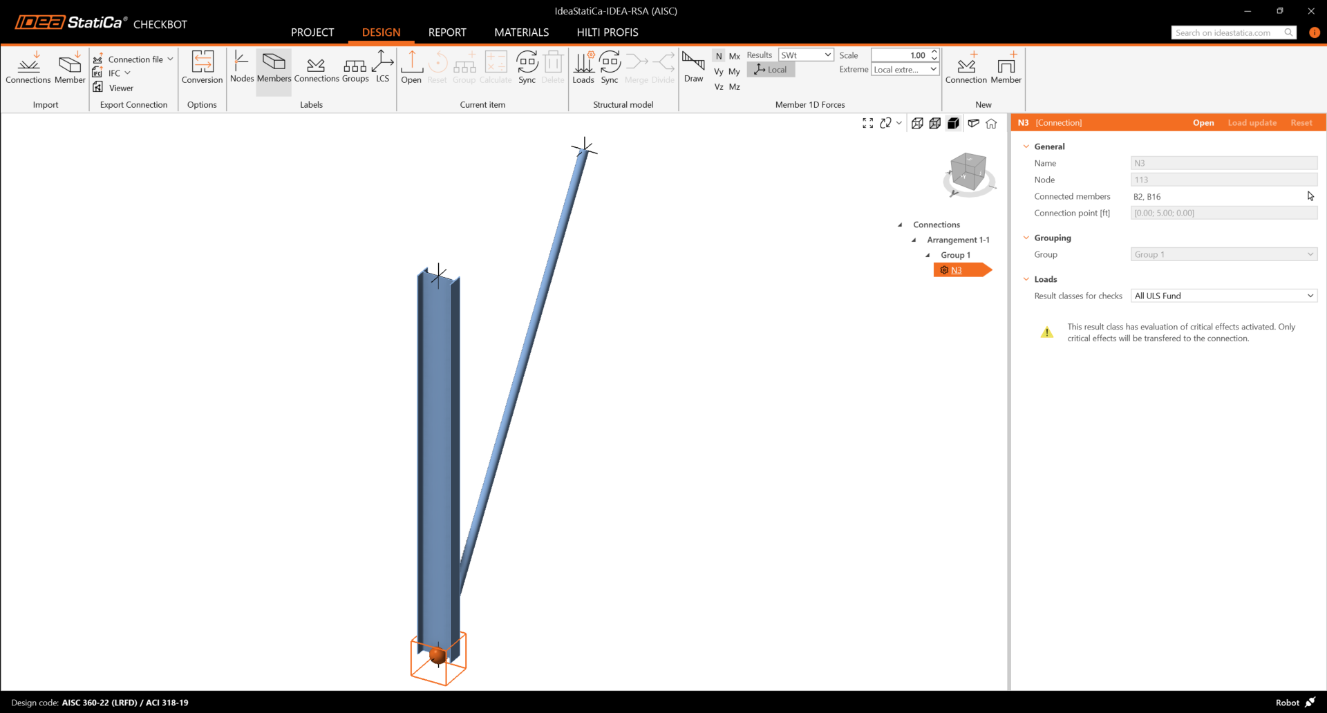
Aceasta va importa stâlpul și efectele de încărcare ale acestuia în Checkbot - cu aceleași coordonate, orientări și dimensiuni ale secțiunilor ca în modelul EF.
Rețineți că numerotarea nodurilor și elementelor dvs. poate fi diferită.
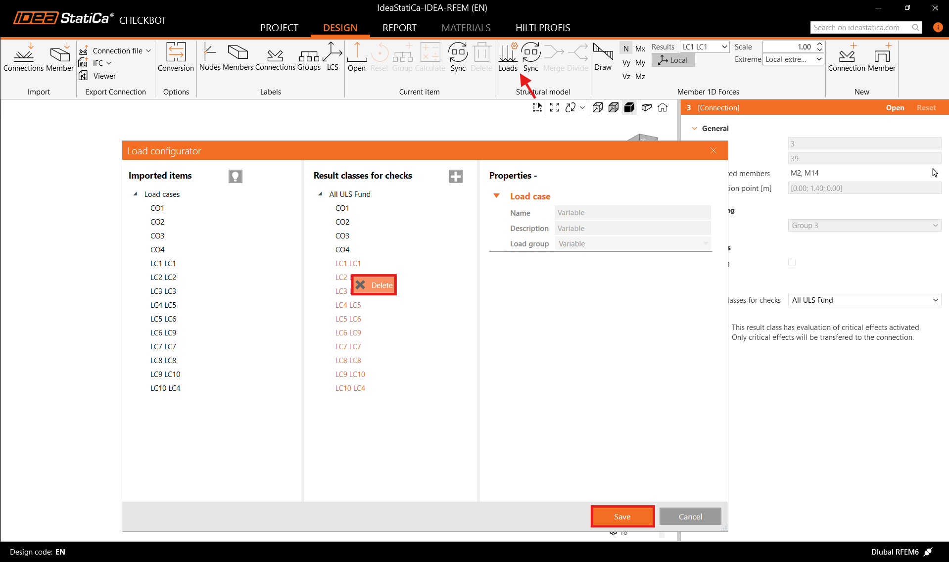
Înainte de a rula analiza, asigurați-vă că revizuiți clasele de rezultate pentru verificări și ajustați cazurile de încărcare în consecință. În dialogul Load configurator, puteți vedea toate cazurile de încărcare și combinațiile de încărcări importate în stânga, iar clasele de rezultate utilizate pentru verificări în mijloc. Dacă unele cazuri de încărcare nu sunt relevante pentru verificarea proiectului dvs., excludeți-le făcând clic dreapta pe încărcările selectate și eliminându-le din lista claselor de rezultate.
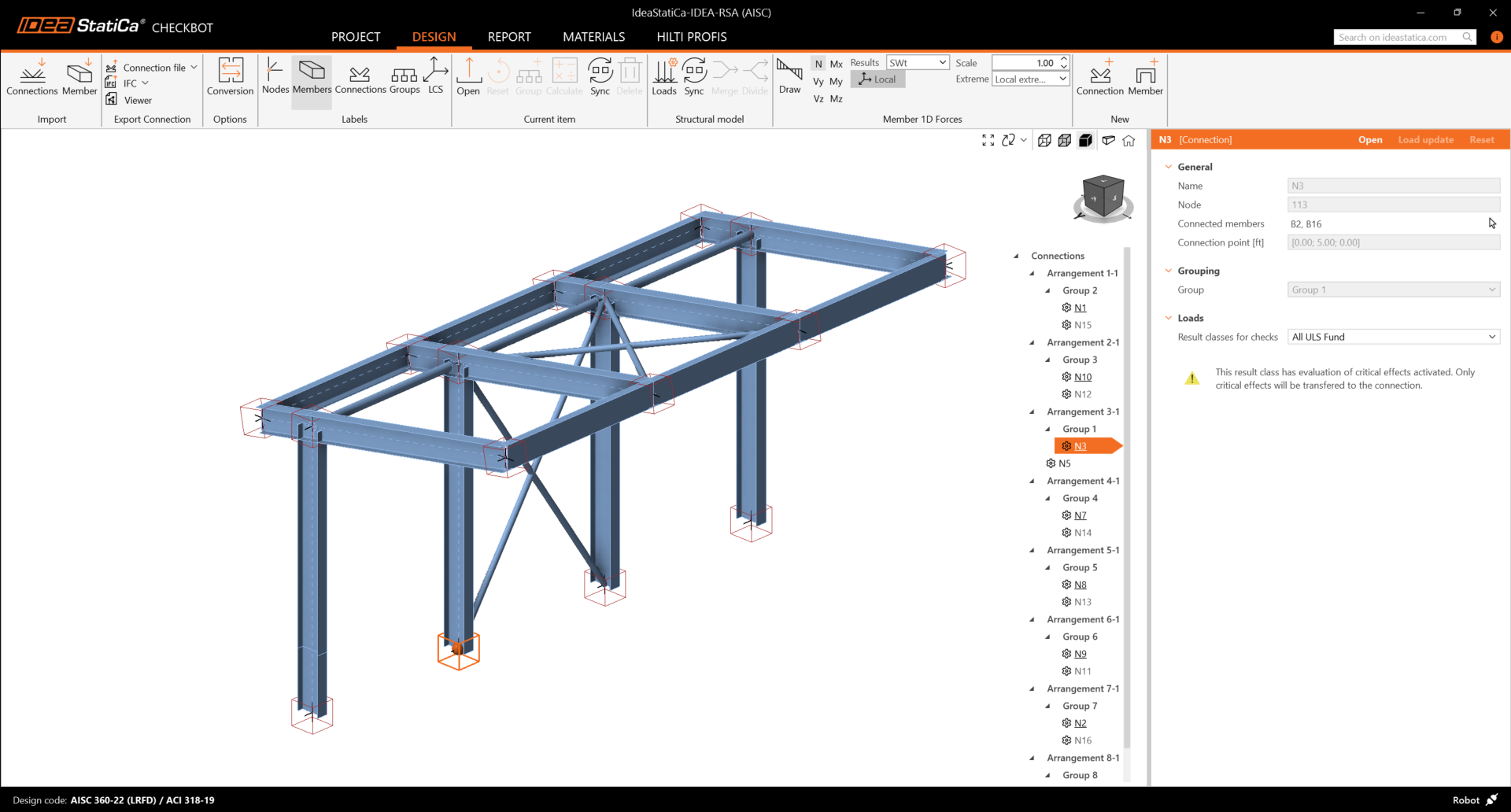
Rețineți că spațiul de lucru 3D este conceput pentru a afișa o prezentare generală a structurii importate și nu o vedere detaliată a îmbinărilor efective. Pentru mai multe informații despre Checkbot, consultați aici.
Pentru mai multe soluții EF, puteți importa, de asemenea, mai multe îmbinări în Checkbot în același mod ca mai sus. În loc să selectați un nod și elementele conectate, puteți selecta mai multe noduri și elemente și să le importați pe toate deodată.
Geometrie
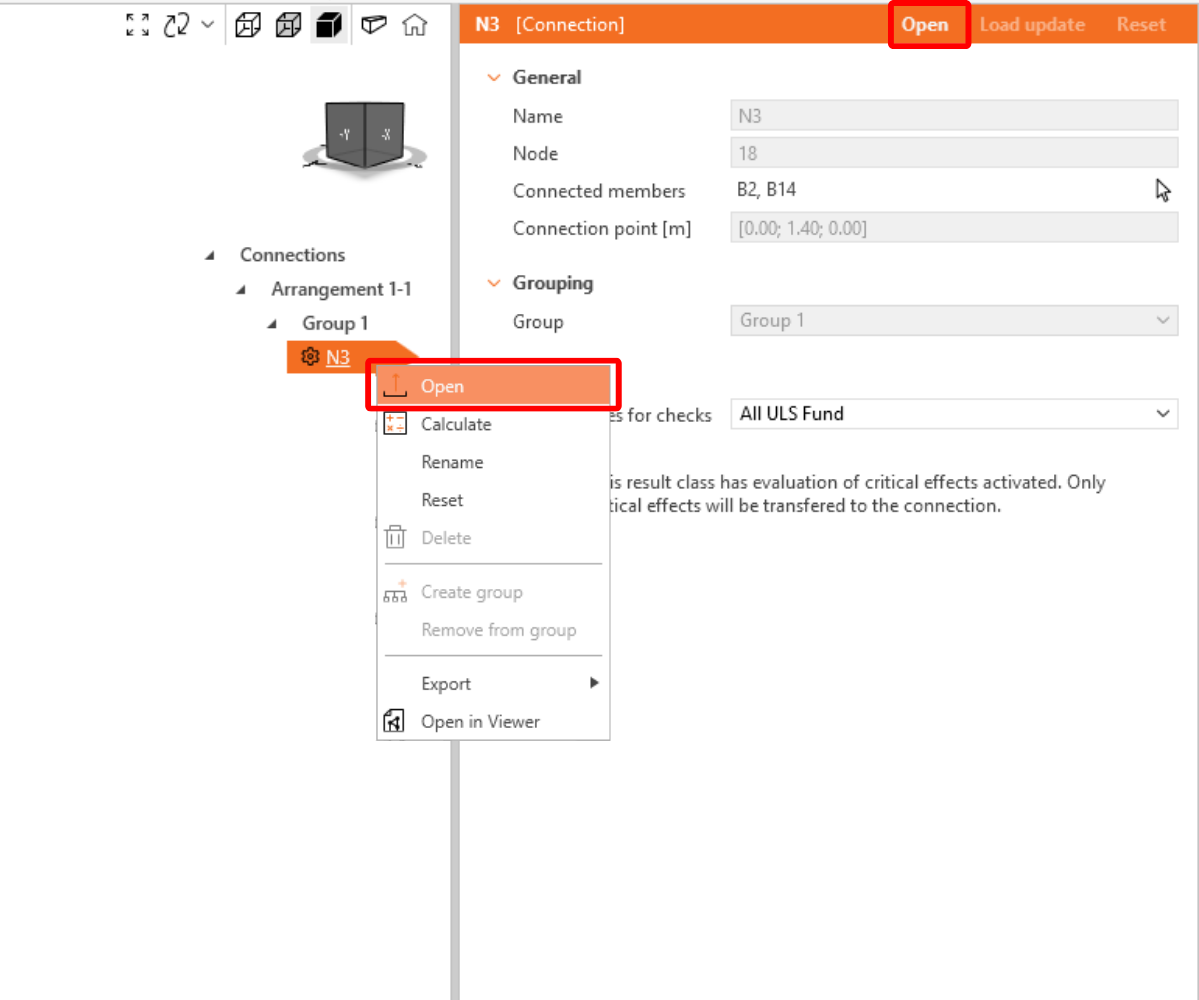
În lista elementelor de proiect din secțiunea Connections, cu o îmbinare selectată în Checkbot, puteți fie să faceți clic dreapta și să selectați Open , fie să faceți clic pe comanda din panglică Open pentru a începe proiectarea, verificarea conform codului și generarea rapoartelor.
Setările elementelor sunt preluate din aplicația FEA originală. Puteți, totuși, să modificați dimensiunea secțiunii oricărui element în ecranul principal al Checkbot, dar aceasta va întrerupe legătura cu aplicația FEA în această sesiune, cu excepția cazului în care este sincronizată din nou.
Îmbinarea importată este deschisă în aplicația IDEA StatiCa Connection.
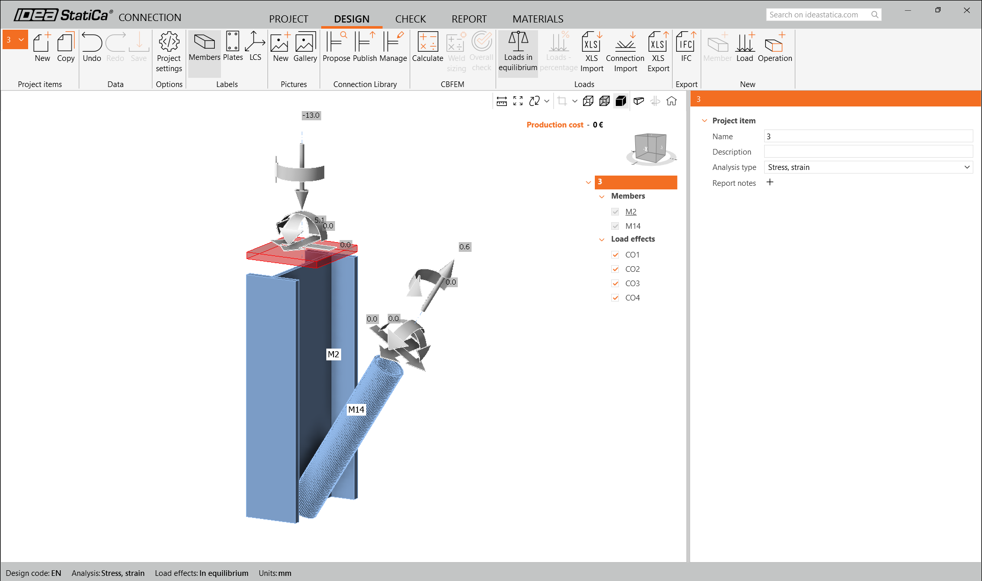
Este posibil să nu vedeți nicio încărcare sau să vedeți încărcări diferite față de soluția dvs. FEA, în funcție de modul în care au fost definite combinațiile de grupuri de încărcări. În mod implicit, IDEA StatiCa va alege combinația cea mai defavorabilă în scopul verificării conform codului. (* Unele soluții BIM nu pot stoca rezultatele combinațiilor de grupuri de încărcări)
Pentru mai multe informații despre încărcări, consultați aici.
Proiectare
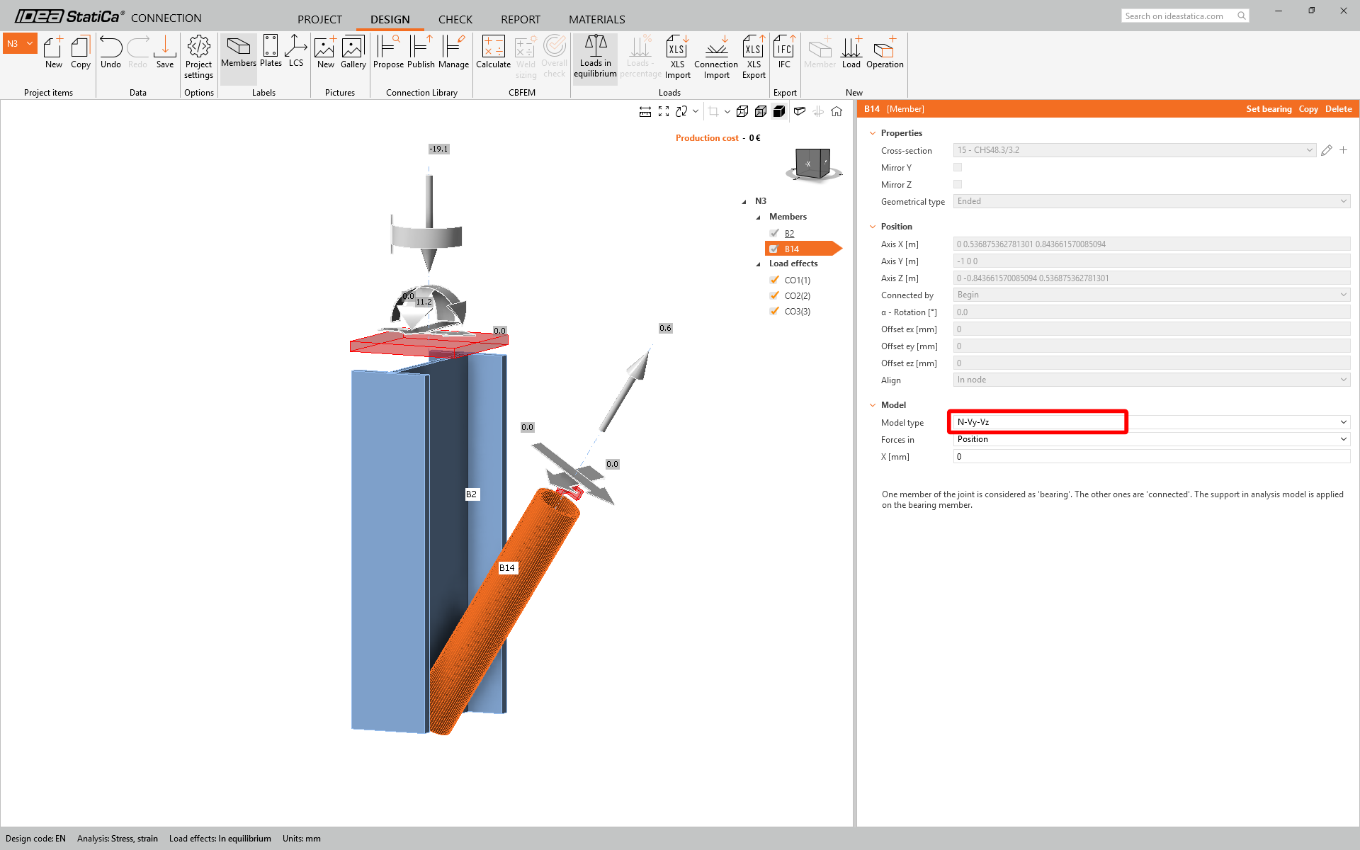
Vom folosi o îmbinare cu un singur șurub pentru diagonala de contravântuire. Pentru acest tip de îmbinare, trebuie să modificăm și Tipul de model al elementului diagonal la N-Vy-Vz. Selectați diagonala din lista de elemente și modificați tipul de model din lista derulantă.
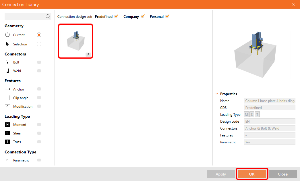
Vom folosi Connection Library pentru a genera o îmbinare. Selectați Propose și IDEA StatiCa va propune soluții posibile pentru geometria curentă.

Connection Library vă prezintă soluțiile posibile pentru geometria curentă. Alegeți șablonul Column I base plate 4 bolts diagonal bolted weak și apăsați OK.
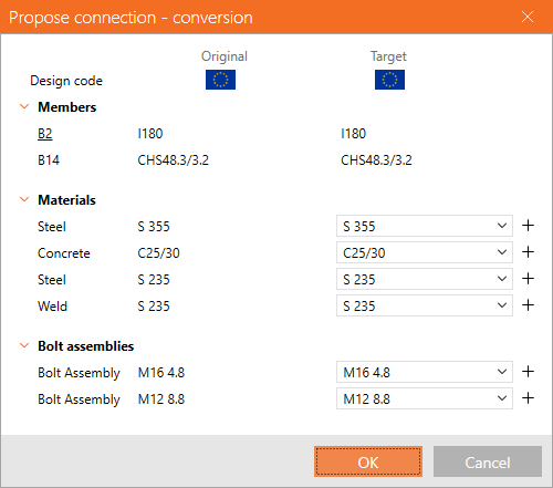
Acceptați valorile propuse în fila de conversie și apăsați OK.
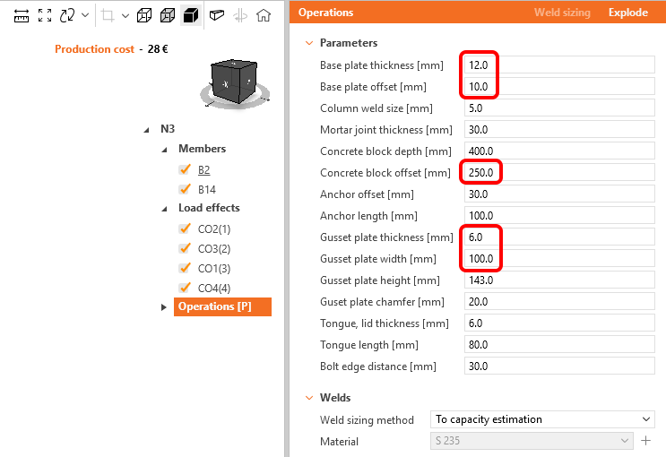
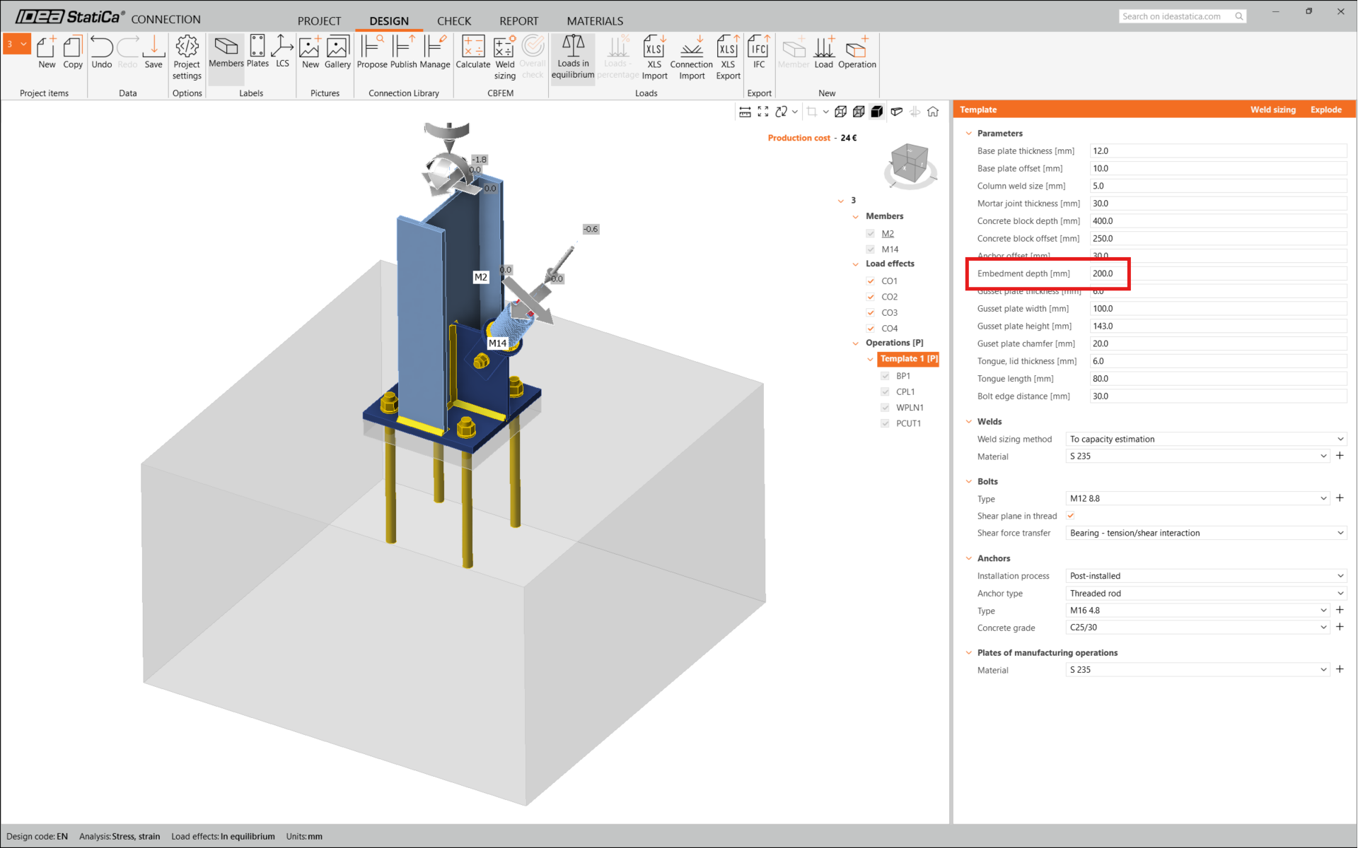
Editați parametrii acestui șablon pentru a corespunde proiectării dorite – Grosimea plăcii de bază la 12 mm, Decalajul plăcii de bază la 10 mm, Decalajul blocului de beton la 250 mm, Grosimea plăcii de nod la 6 mm și Lățimea plăcii de nod la 100 mm.
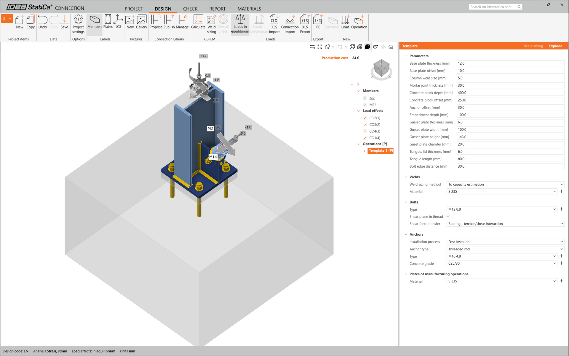
Acesta este aspectul inițial al îmbinării.
Aceasta finalizează proiectarea îmbinării pentru placa de bază a stâlpului cu diagonală de contravântuire.
Verificarea conform codului și Raport
Rulați acum o verificare conform codului folosind pictograma Calculate din panoul CBFEM din bara de instrumente superioară.
În cadrul IDEA StatiCa Connection, puteți efectua mai multe tipuri de analize și verificări conform codului. Pentru mai multe informații, consultați aici.

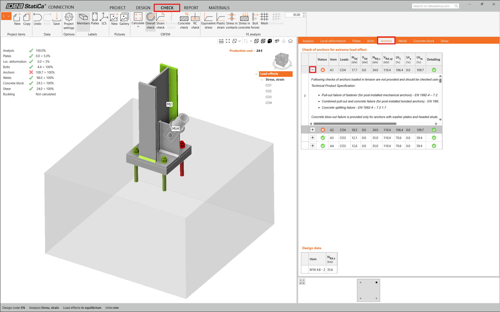
Rezultatele pot fi inacceptabile. În acest caz, ancorele nu satisfac verificarea din cauza capacității de calcul reduse.
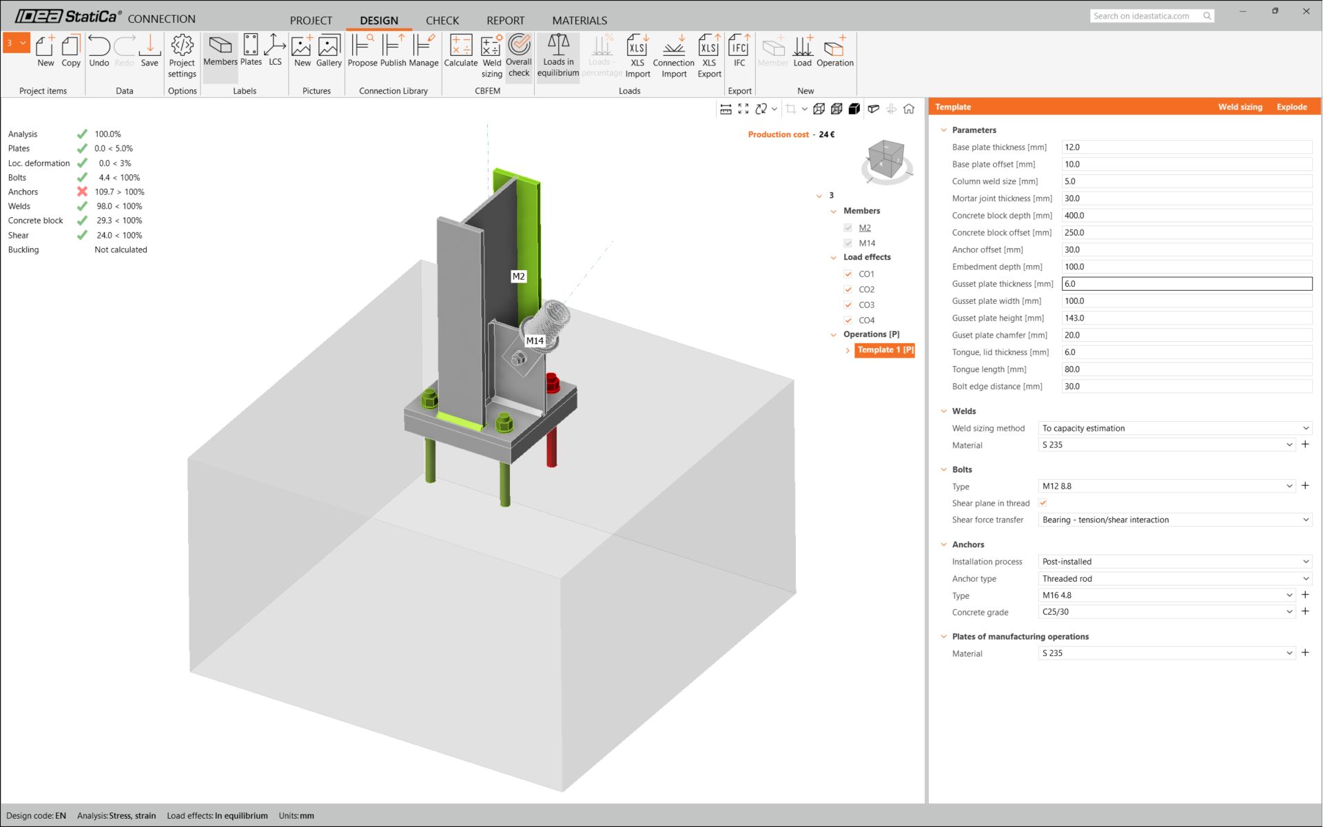
Puteți accesa fila Check pentru a examina rezultatele și a analiza mai detaliat ancorele, extinzând calculul cu simbolul '+'. Puteți observa că ancorele cedează la întindere în blocul de beton.
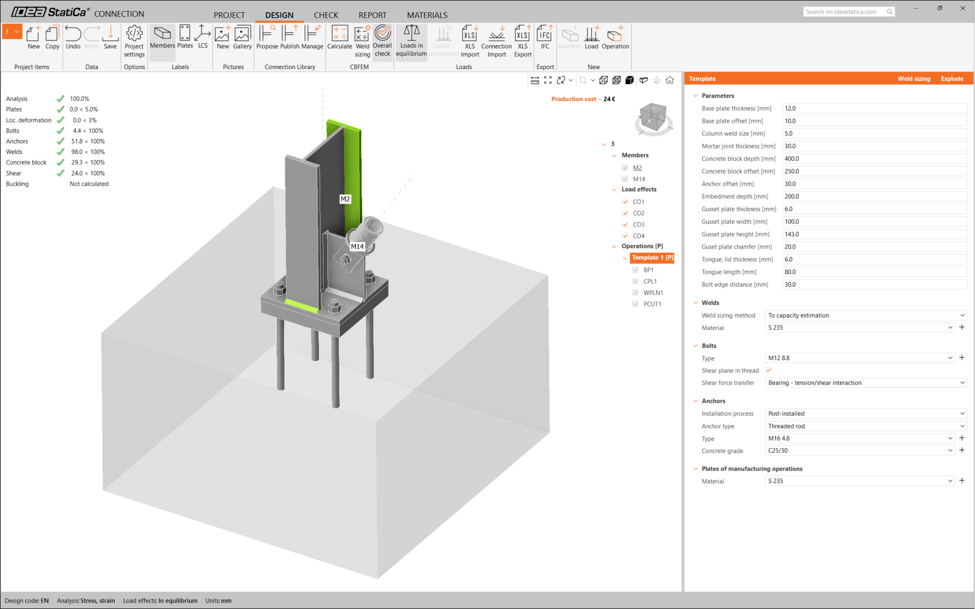
Trebuie să optimizăm proiectarea pentru a găsi soluția care satisface verificările. Reveniți la fila Design , faceți clic pe operație și modificați Lungimea de ancoraj la 200 mm. Apoi rulați din nou analiza și verificarea conform codului.
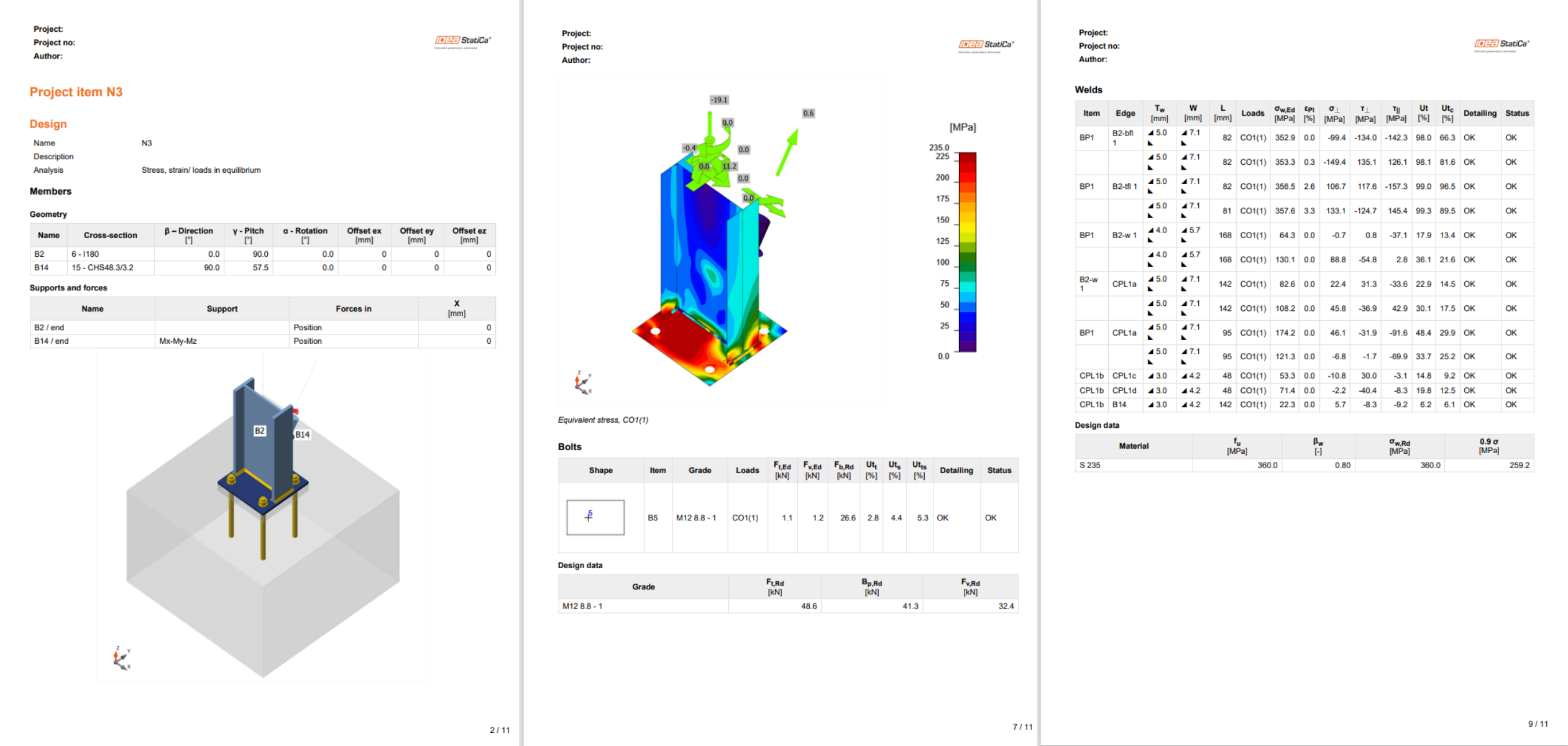
După finalizarea verificării conform codului, în fila Report puteți crea raportul care conține rezultatele și diagramele pentru modelul de îmbinare.
Raportul poate fi tipărit sau salvat în mai multe formate. Pentru mai multe informații, consultați aici.
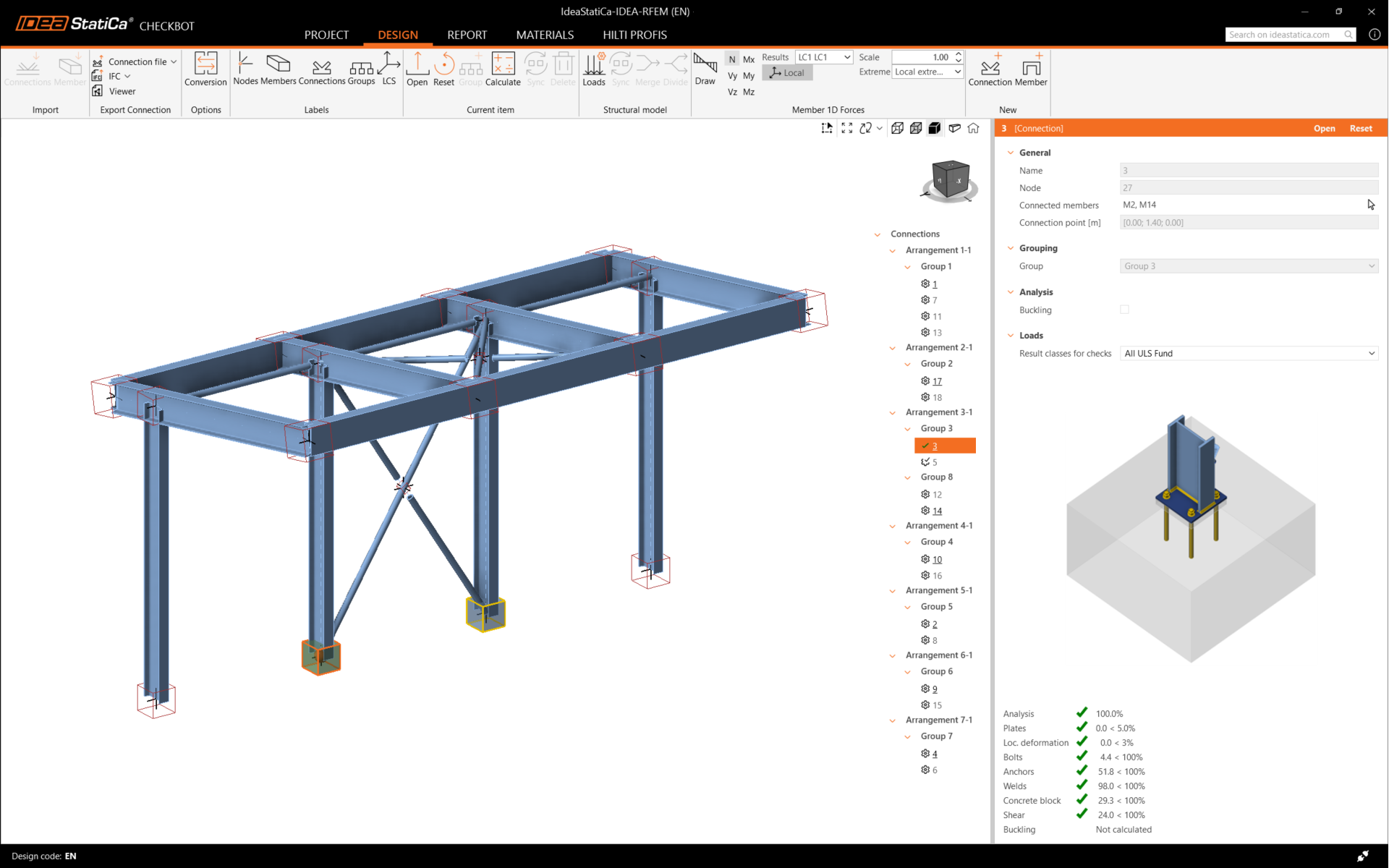
Salvați această îmbinare și reveniți la fereastra Checkbot (puteți păstra fereastra Connection deschisă).
În Checkbot, veți vedea o bifă verde lângă îmbinare și caseta nodului colorată în verde. Aceasta înseamnă că îmbinarea a trecut toate verificările conform codului. În panoul Connection, puteți vedea, de asemenea, o reprezentare a îmbinării și un rezumat al rezultatelor verificării conform codului.
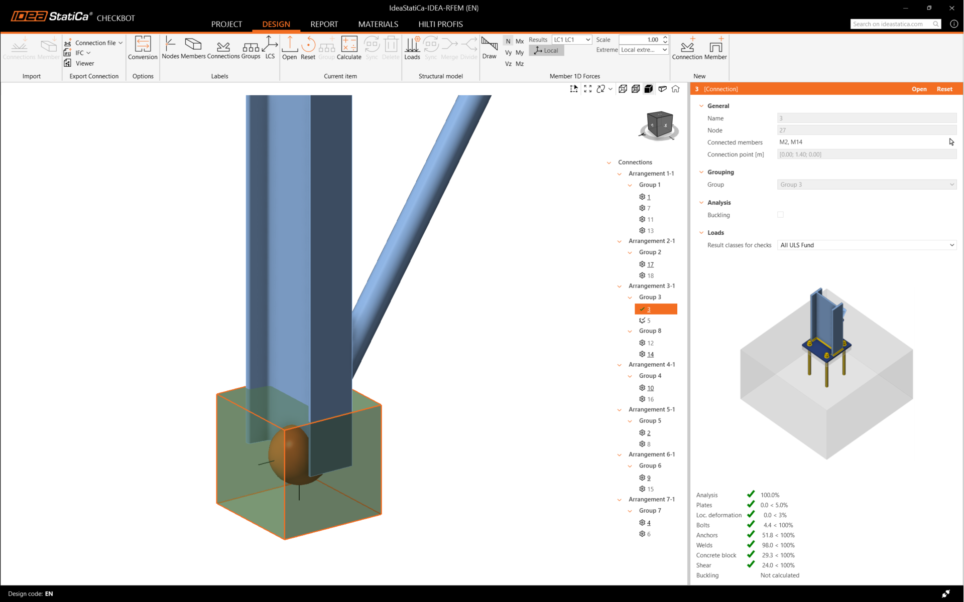
În exemplul de mai jos, puteți observa că doar o singură îmbinare a trecut verificarea conform codului corespunzătoare, în timp ce celelalte îmbinări urmează să fie proiectate.
Puteți continua cu proiectarea celorlalte îmbinări, fie una câte una, fie folosind fluxurile de lucru în bloc.
Sincronizați îmbinările
Uneori, există modificări în modelul dvs. de calcul structural (FEA), cum ar fi o secțiune transversală diferită a elementului sau o încărcare mărită. Acestea pot fi sincronizate între Checkbot și modelul FEA.
Există două alternative posibile:
- Sincronizarea elementului curent (dacă unul sau mai multe noduri sunt selectate)
- Sincronizarea întregului model structural importat
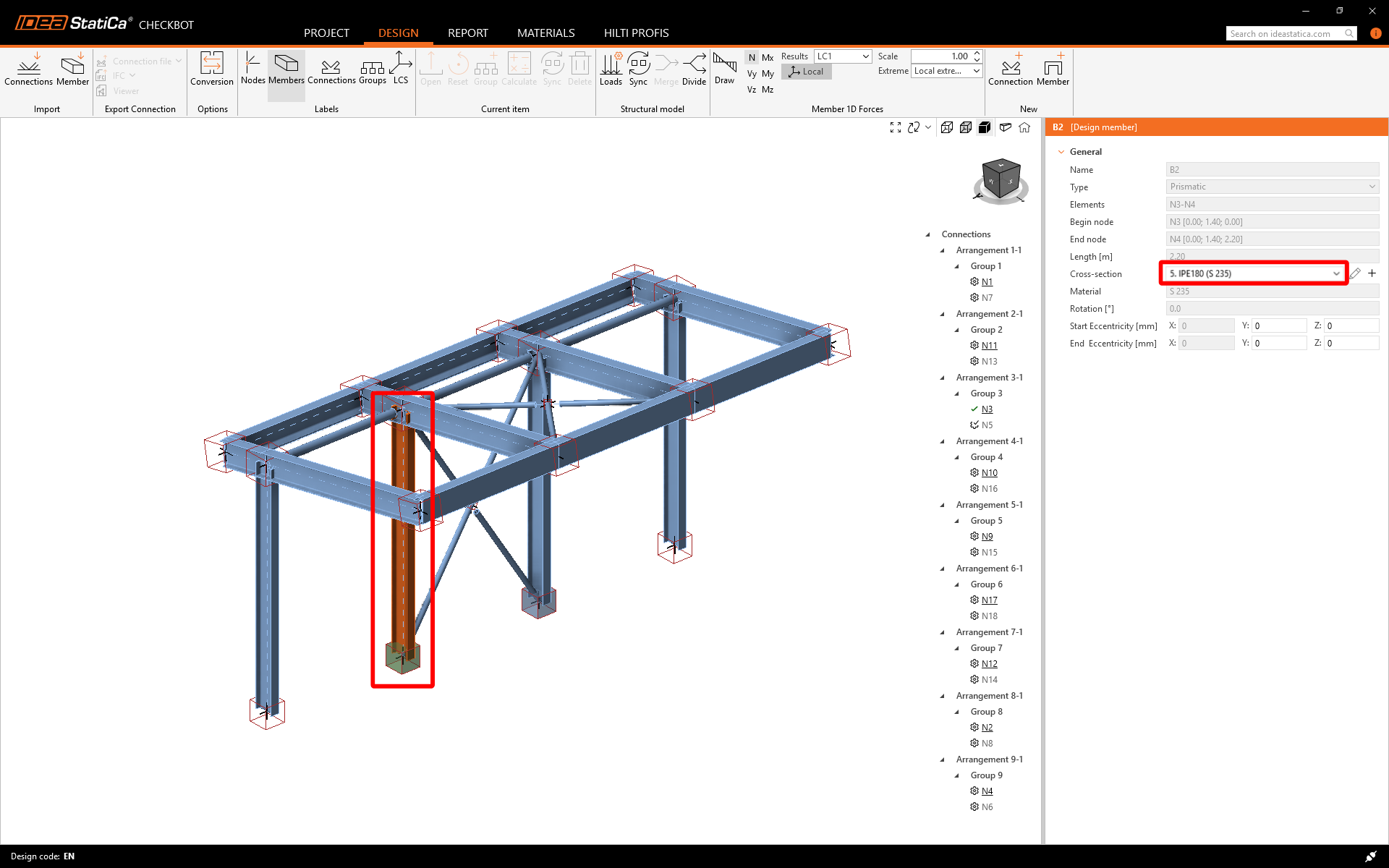
Pentru a testa această funcție, puteți modifica secțiunea transversală a unui element în aplicația dvs. FEA. Nu uitați să re-analizați modelul FEA pentru a sincroniza și rezultatele actualizate.
În Checkbot, selectați îmbinările proiectate (pot fi mai multe) și din panoul Element curent selectați Sincronizare.

Proiectul Checkbot va fi actualizat. Proiectarea îmbinării finalizate anterior este păstrată, dar verificările conform codului vor fi invalidate. Puteți observa că stâlpul este acum actualizat - corespunzând modificării din modelul FEA.
Efectuați din nou verificarea conform codului pentru îmbinările evidențiate selectând Calculați din panoul Element curent.
Dacă îmbinările nu oferă rezultatele dorite, le puteți deschide din nou pentru a optimiza proiectarea (de exemplu, să le consolidați dacă nu trec verificarea conform codului sau să le ușurați dacă gradul de utilizare este prea scăzut).
Modificările mai mari în modelul FEA pot necesita sincronizarea întregului model structural în Checkbot, în loc de doar elementul curent.

Vă rugăm să rețineți că elementele sau încărcările nou adăugate nu pot fi sincronizate, iar un nou proiect Checkbot trebuie creat.
Ați conectat cu succes RFEM/RSTAB cu IDEA StatiCa Connection prin intermediul Checkbot.