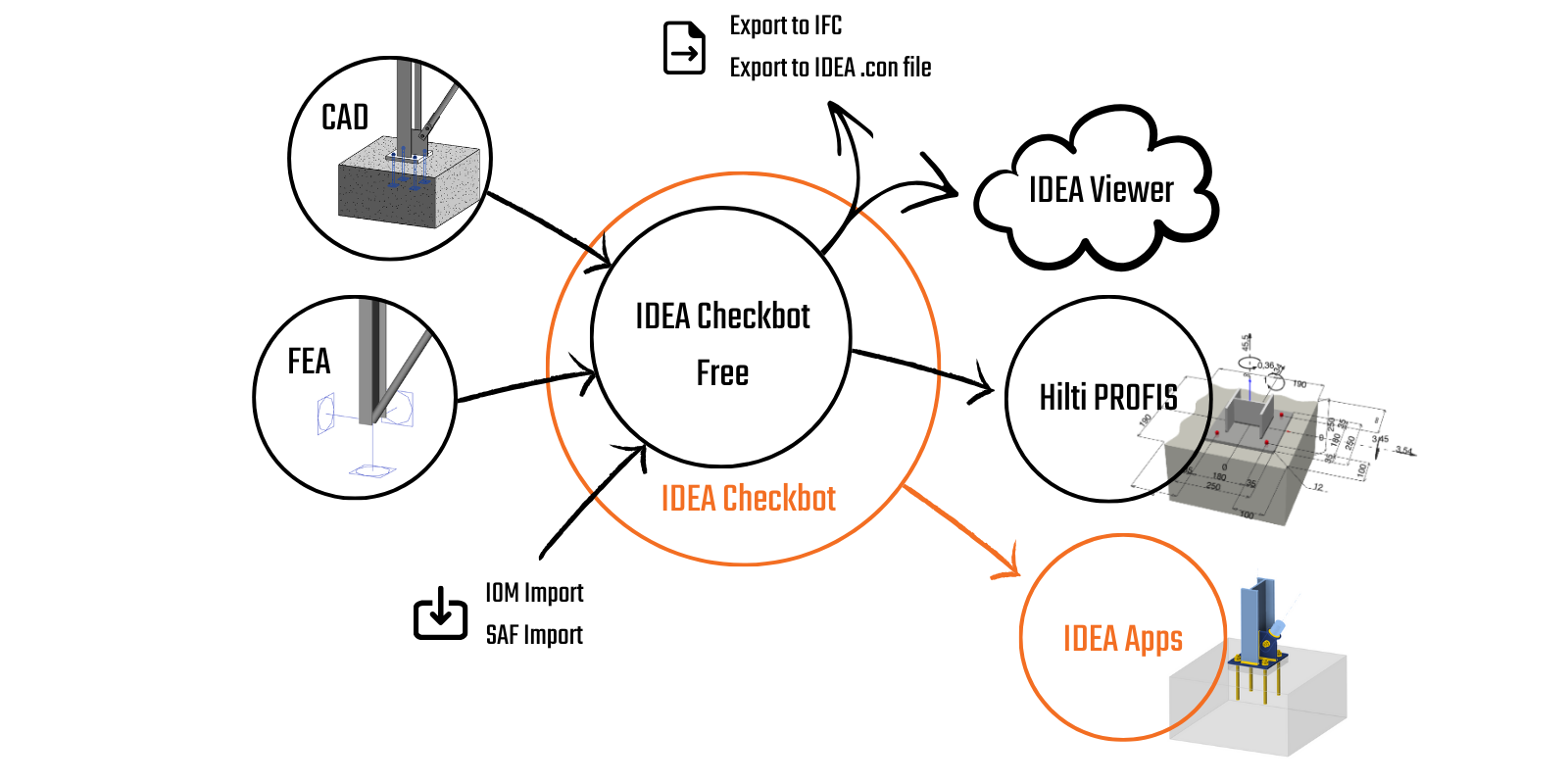
IDEA StatiCa Checkbot gestionează fluxurile de lucru BIM și vă oferă:
- O listă clară a tuturor elementelor importate, inclusiv starea verificat/neverificat
- Raport pentru toate elementele analizate și verificate
- Vizualizare 3D a elementelor și încărcărilor importate
- Un tabel de conversie pentru materiale și secțiuni transversale
- Gestionarea combinațiilor de încărcări
Checkbot este disponibil atât cu licența comercială plătită, cât și cu licența Basic gratuită. Singura diferență este că Checkbot Free nu vă permite să proiectați și să calculați elementele de proiectare în celelalte aplicații, cum ar fi Connection, Member sau Detail.
Principalul avantaj al instrumentului este că înțelege nu doar geometria structurii originale, ci, mai important, încărcările și eforturile interioare rezultate din analiză. Orice inginer care transformă eforturile interioare dintr-o analiză în alta înțelege cât de dificil poate fi să păstreze toate forțele în sistemul de coordonate corespunzător. Checkbot poate face acest lucru pentru sute de combinații de încărcări și zeci de instrumente diferite provenind din orice software suportat.
Importul datelor în Checkbot
1) Legături BIM
Checkbot funcționează ca o aplicație de sine stătătoare, permițând utilizatorilor să deschidă orice proiect structural folosind legături BIM direct în software-ul terților. Bara de comenzi pentru import diferă ușor în funcție de tipul programului sursă: CAD sau FEA (software de analiză cu elemente finite). Puteți verifica oricând integrările suportate pentru software-ul CAD/FEA pentru oțel, împreună cu limitările cunoscute, și puteți vedea o listă a versiunilor suportate ale aplicațiilor terților.
Urmând tutoriale pas cu pas, veți învăța cum să proiectați și să efectuați verificarea conform codului pentru îmbinările și elementele dvs. folosind legătura BIM dintre IDEA StatiCa și alte software-uri.
- ... și altele
Când un proiect Checkbot este creat utilizând legătura BIM, se deschide cu un ecran gol și nodurile și elementele sau pereții trebuie importați.
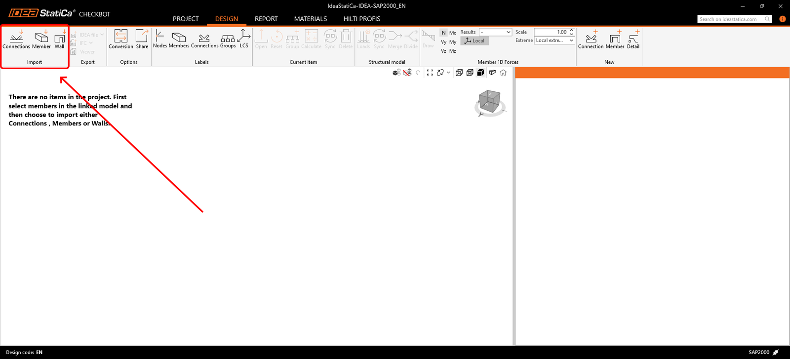
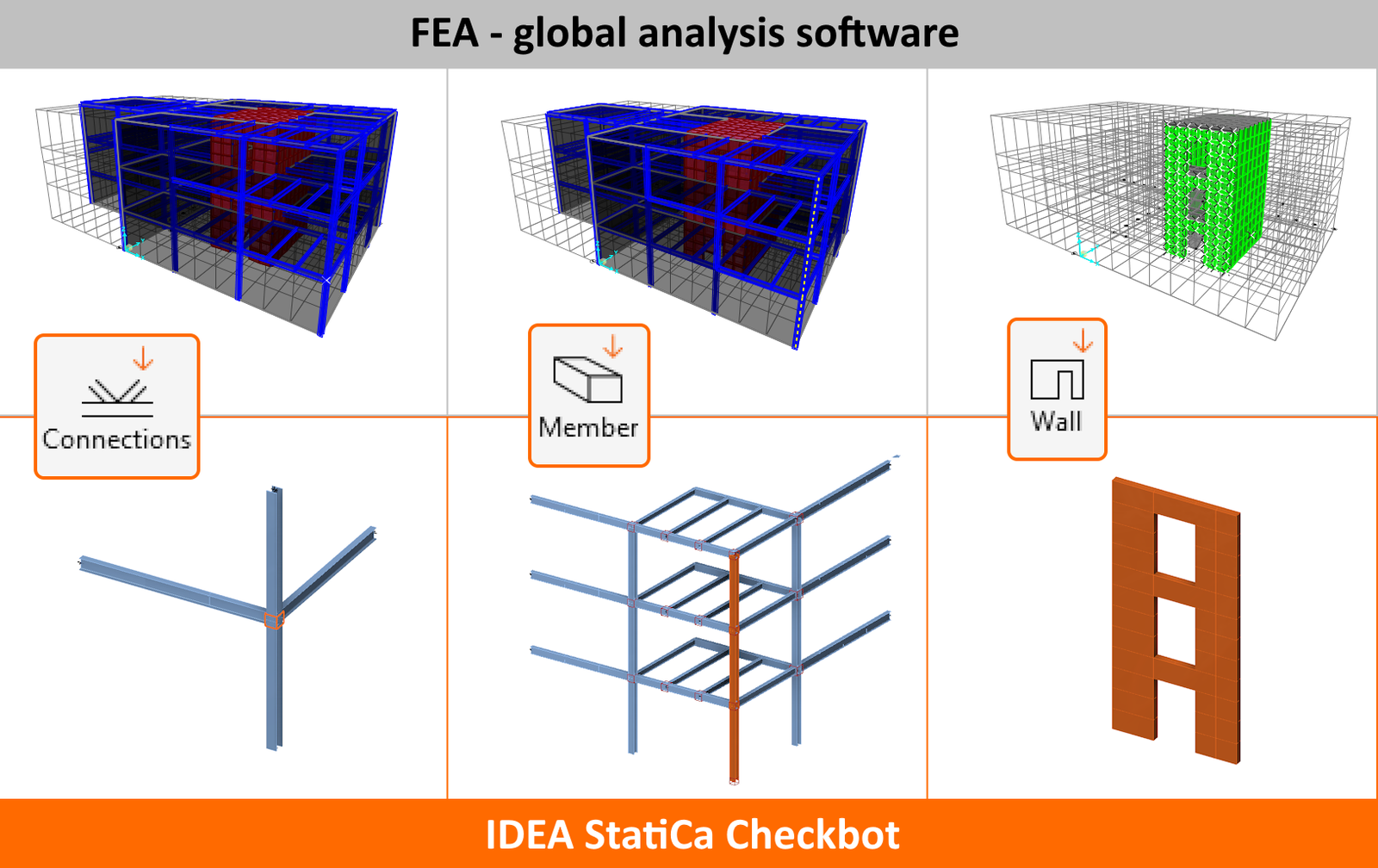
Importul îmbinărilor/elementelor
Utilizați următoarele comenzi pentru a importa datele din software-ul FEA sau CAD în execuție. Puteți importa un singur element, o parte din structură sau întreaga structură dintr-o dată. Este posibil să importați ulterior părți ale structurii care nu au fost selectate inițial.
- Connection – importă doar un nod selectat și elementele conectate la acesta
- Member (doar pentru software FEA) – importă elementul selectat, nodurile sale și elementele adiacente
- Wall (doar pentru ETABS/SAP2000) - importă elementele 2D din beton (Pereți)
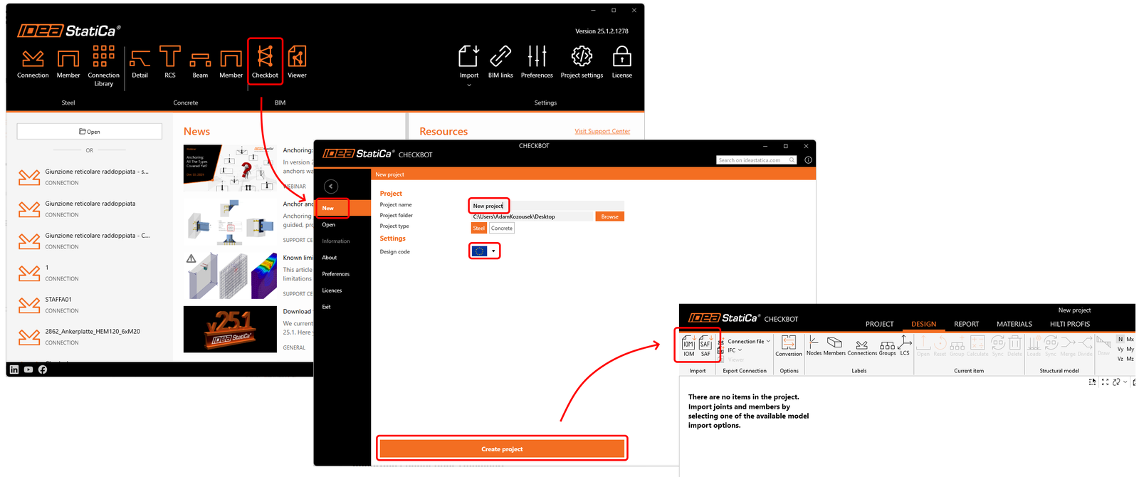
2) SAF/IOM
O altă modalitate de import al datelor din software-ul CAD/FEA este oferită prin utilizarea IDEA Open Model (IOM). Aceasta permite, de asemenea, importul și procesarea formatului larg utilizat Structural Analysis Format (SAF). Un fișier SAF poate fi exportat din SCIA Engineer, software Dlubal, FEM-Design, SOFiSTiK, Risa 3D, FRILO, Allplan, AxisVM, ConSteel și multe altele.
Conversie
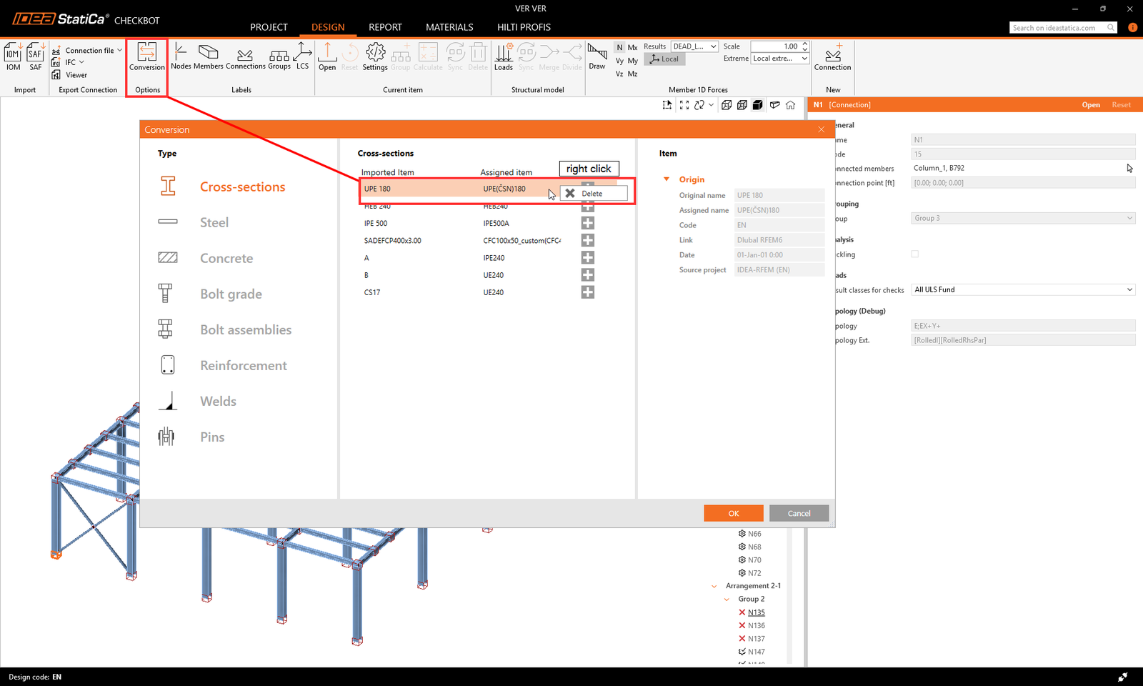
Când o secțiune transversală sau un material nu este recunoscut automat în timpul importului, apare o nouă filă de conversie pentru a-l atribui manual din biblioteca noastră de secțiuni/materiale. Aceste perechi sunt apoi salvate pentru utilizare viitoare în contul dvs. de utilizator și, prin urmare, nu mai trebuie definite din nou.
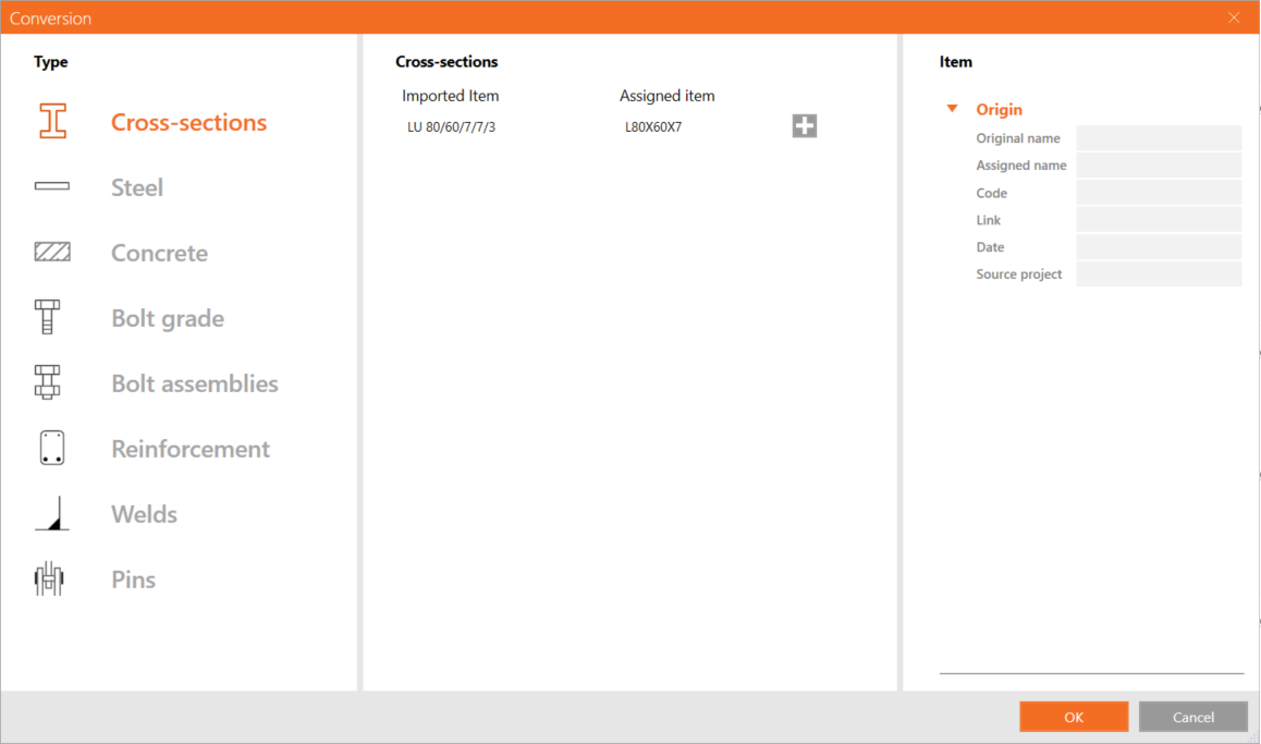
Dacă maparea secțiunii transversale a fost creată incorect sau necesită ajustări, puteți adăuga o nouă mapare făcând clic pe butonul plus sau puteți elimina una existentă făcând clic dreapta și selectând Ștergere.
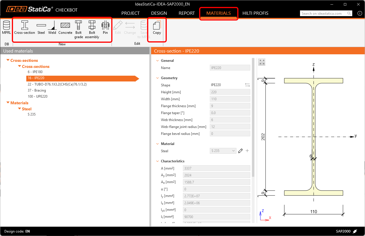
Toate materialele utilizate în Checkbot sunt listate în fila Materiale. Toate materialele și secțiunile transversale importate sunt dezactivate pentru modificări. Pentru a le modifica parametrii, trebuie creată o copie sau adăugat un material complet nou.
Fila de conversie este salvată pentru fiecare cod de proiectare într-un fișier .XML separat în următorul folder:
C:\Users\YOURUSERNAME\AppData\Local\IdeaStatiCa
Aici, fișierele de conversie pot fi modificate manual, șterse complet, salvate ca copie de rezervă sau partajate cu alți utilizatori.
Numerotare și sistem de coordonate local
Numerotarea și sistemul de coordonate local al elementelor în Checkbot și în software-ul terților pot fi diferite. Deoarece Checkbot se bazează pe un algoritm de mapare a încărcărilor, nu este necesar să vă faceți griji. Checkbot recunoaște și identifică elementele corespunzătoare și atribuie în mod fiabil efectele de încărcare corecte acestora.
Cum se lucrează cu Checkbot
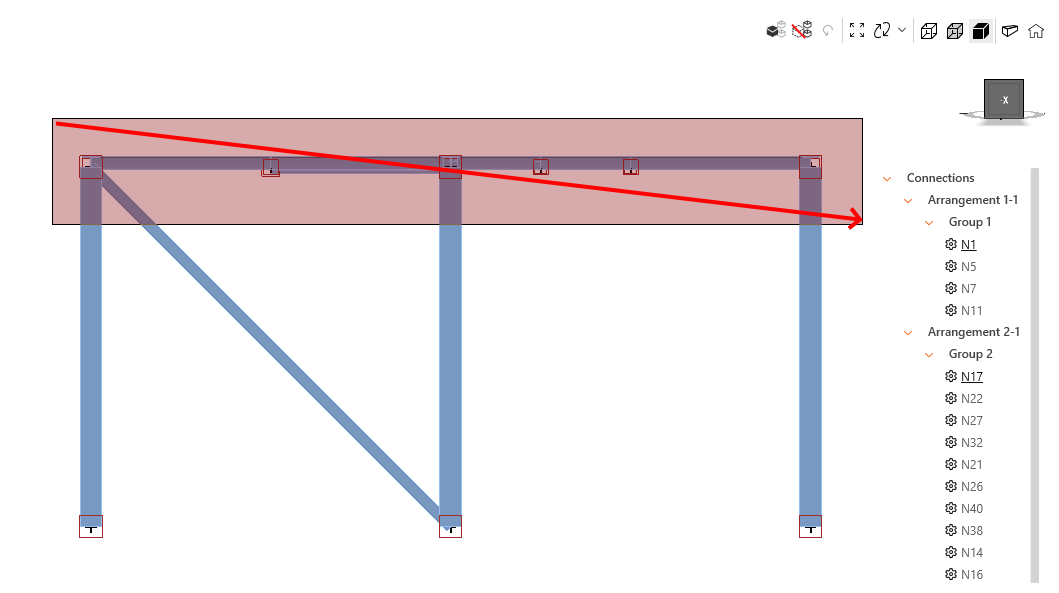
Pentru a efectua o selecție de zonă, pur și simplu trageți de la stânga la dreapta – sunt incluse doar elementele din interiorul zonei de selecție, sau trageți de la dreapta la stânga – sunt incluse și elementele care intersectează zona de selecție. Adăugați element(e) ținând apăsată tasta Ctrl și eliminați cu tasta Shift. Deselectați cu tasta Esc. Ctrl+A selectează toate elementele din scena 3D.
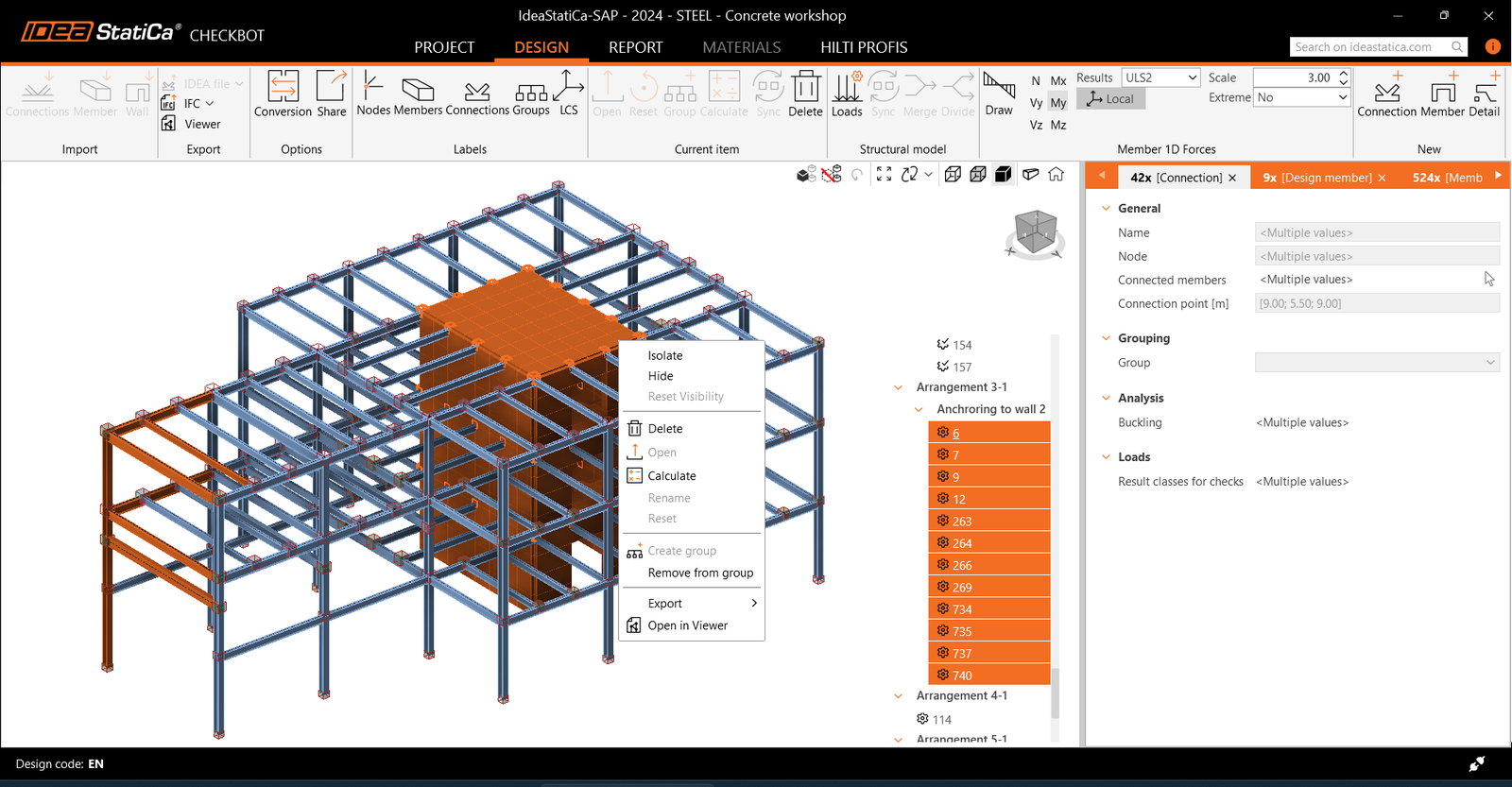
Meniul contextual este accesibil prin clic dreapta și oferă acțiuni atât pentru entitățile selectate, cât și pentru cele evidențiate. Permite executarea operațiilor comune direct în scena 3D, cum ar fi ștergerea elementelor.
Controalele de vizibilitate – Ascundere, Izolare și Resetare permit utilizatorilor să gestioneze afișarea entităților în scena 3D. Aceste controale sunt accesibile prin meniul clic dreapta, pictogramele din bara de instrumente a scenei 3D sau tastele rapide Ctrl+H, Ctrl+I și Ctrl+R.
Când sunt selectate mai multe entități, grila de proprietăți afișează file cu acele entități grupate după tip (Connection, element de proiectare etc.). Fiecare filă oferă o prezentare generală a entităților corespunzătoare și permite gestionarea rapidă a selecției prin clic dreapta pe filă - Selectați doar... și Eliminați din selecție.
Scena 3D funcționează cel mai bine cu „Standard pentru grafică 3D" setat la „Direct3D" în Preferințe.
Configurarea încărcărilor
Configuratorul de încărcări afișează cazurile de încărcare și combinațiile de încărcări importate. Prima coloană listează toate cazurile de încărcare și combinațiile importate din modelul FEA conectat. A doua coloană afișează cazurile de încărcare și combinațiile de încărcări din clasele de rezultate utilizate pentru calcule în proiectul Checkbot. În mod implicit, se utilizează o clasă de rezultate cu toate combinațiile de încărcări. În plus, a treia coloană afișează descrieri detaliate ale entității selectate în prezent.
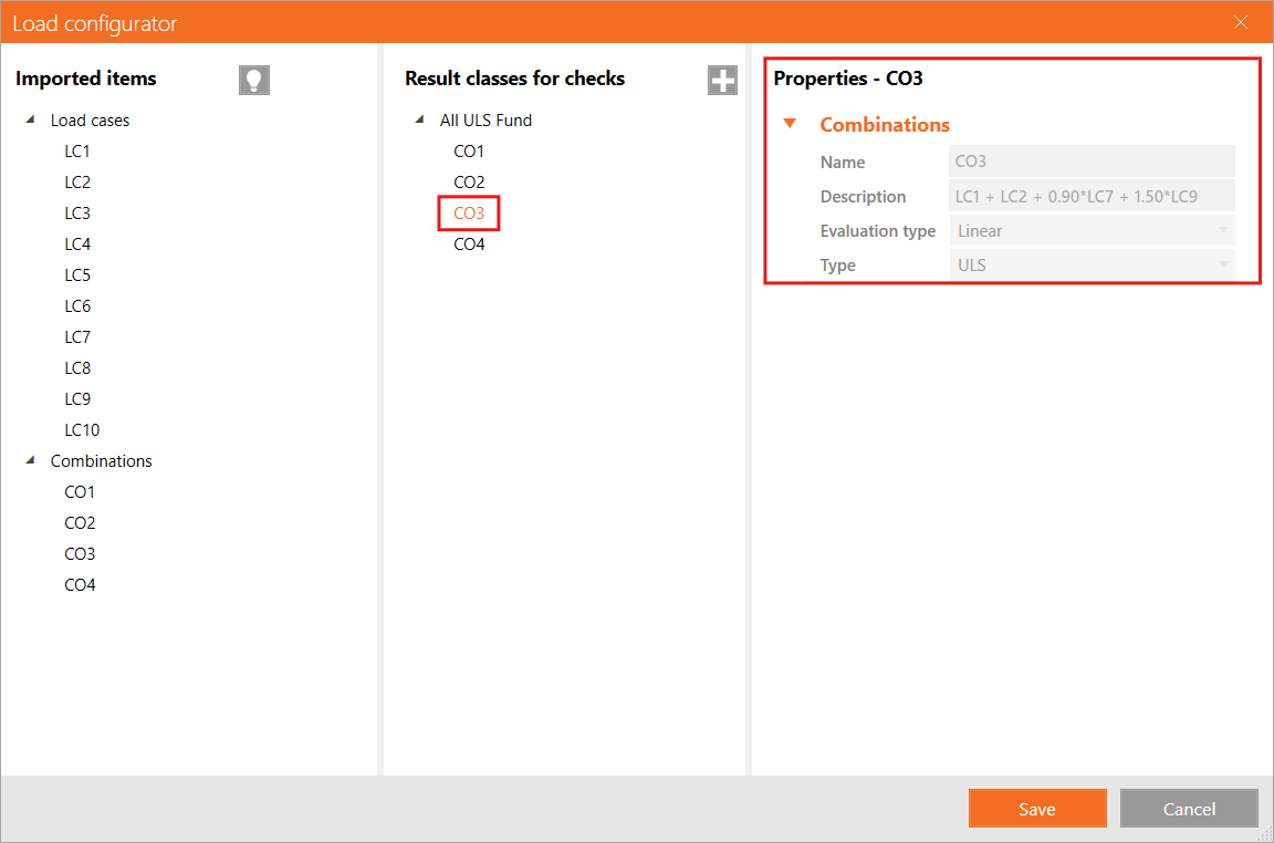
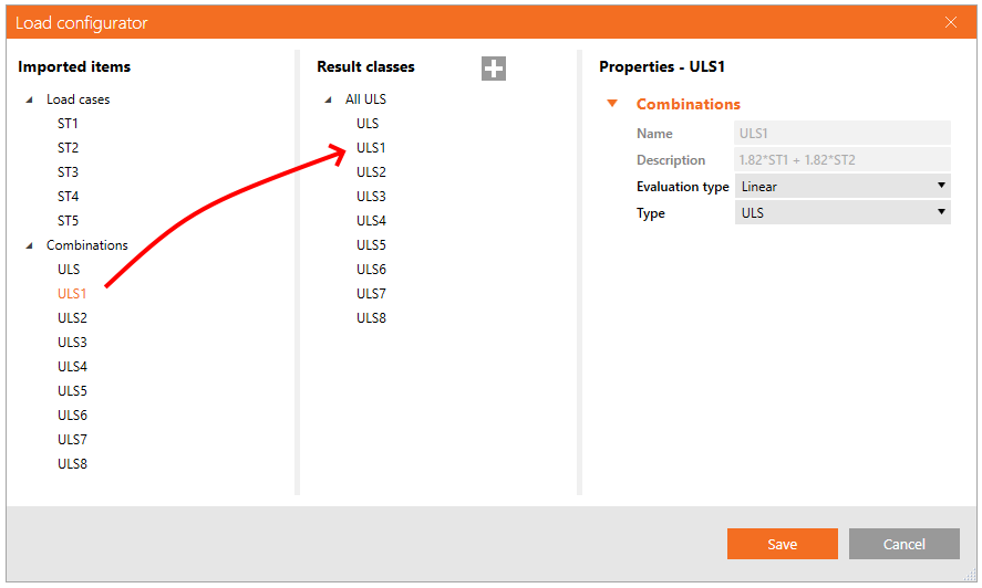
Efectele de încărcare importate pot fi reatribuite manual la Clase de rezultate. Clasele de rezultate sunt destinate sortării efectelor de încărcare în grupuri specifice, ceea ce poate simplifica și accelera procesul de proiectare. Clasele de rezultate pot fi adăugate folosind pictograma „+" și eliminate cu un clic dreapta al mouse-ului. Cazurile de încărcare și combinațiile pot fi atribuite unei clase de rezultate prin tragerea lor din prima coloană sub clasa de rezultate corespunzătoare din a doua coloană.
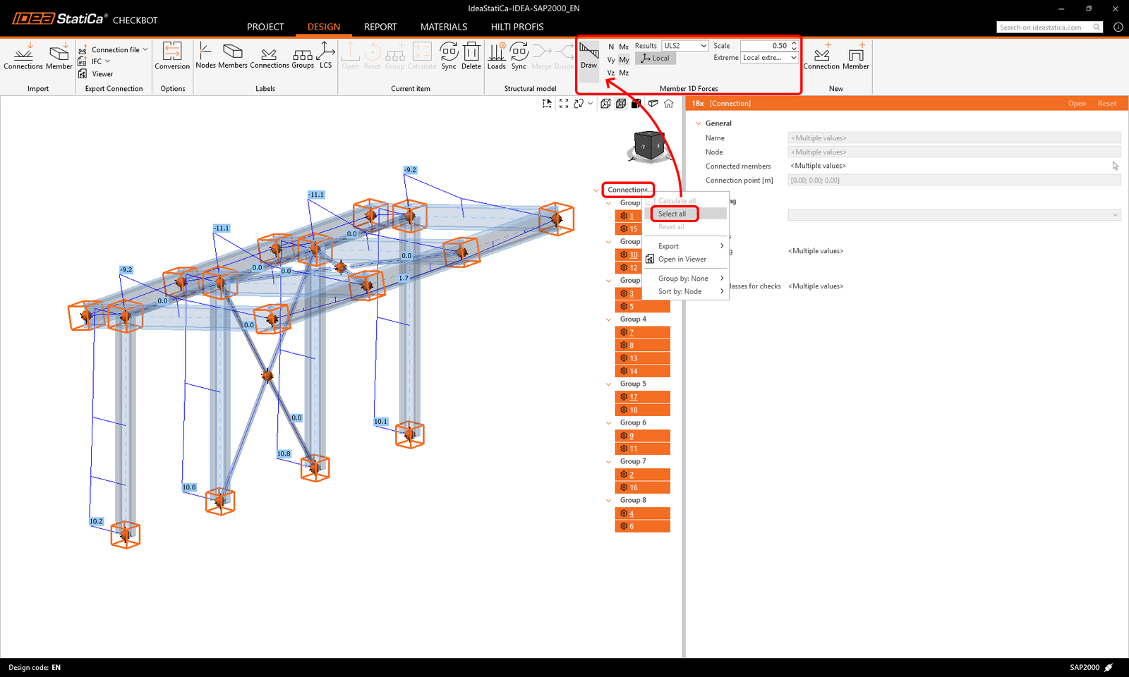
Checkbot vizualizează, de asemenea, eforturile interioare ale combinațiilor importate. Selectați partea din structură prin tragere sau clic dreapta pe lista de elemente - Selectați toate, apoi faceți clic pe Desenați pentru a afișa eforturile interioare.
Vă rugăm să rețineți că nu toate combinațiile de încărcări sunt compatibile cu Checkbot (de ex., combinații dinamice, combinații neliniare), în funcție de software-ul FEA. Unele combinații pot fi importate ca cazuri de încărcare, ceea ce însă nu afectează rezultatele. Verificați întotdeauna limitările cunoscute ale fiecărei legături BIM:
Configuratorul de încărcări vă permite să activați evaluarea efectelor critice* în structuri complexe. Această funcție selectează cazurile de încărcare și combinațiile cu efecte de încărcare maxime și minime, filtrând restul. Ia în considerare tensiunile din fibrele superioare și inferioare ale secțiunii transversale pentru a accelera calculele de verificare conform codului.
* Funcția Evaluare efecte critice a fost eliminată și înlocuită de funcția Calculați extreme de încărcare începând cu versiunea 25.1.2.
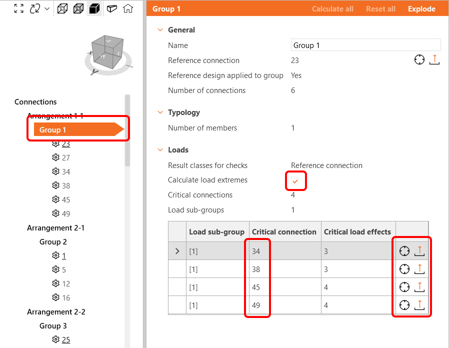
Funcția Calculați extreme de încărcare
În proiectele cu multe noduri și combinații de încărcări, îmbinări similare cu efecte de încărcare foarte asemănătoare sunt analizate în mod repetat. Pentru a accelera procesul de calcul, puteți utiliza butonul Calculați extreme de încărcare pentru a defini doar extremele de încărcare care conțin efectele de încărcare critice. Aceasta va reduce numărul de efecte de încărcare examinate, precum și timpul de calcul. Citiți mai multe în acest articol.
Grupare dinamică
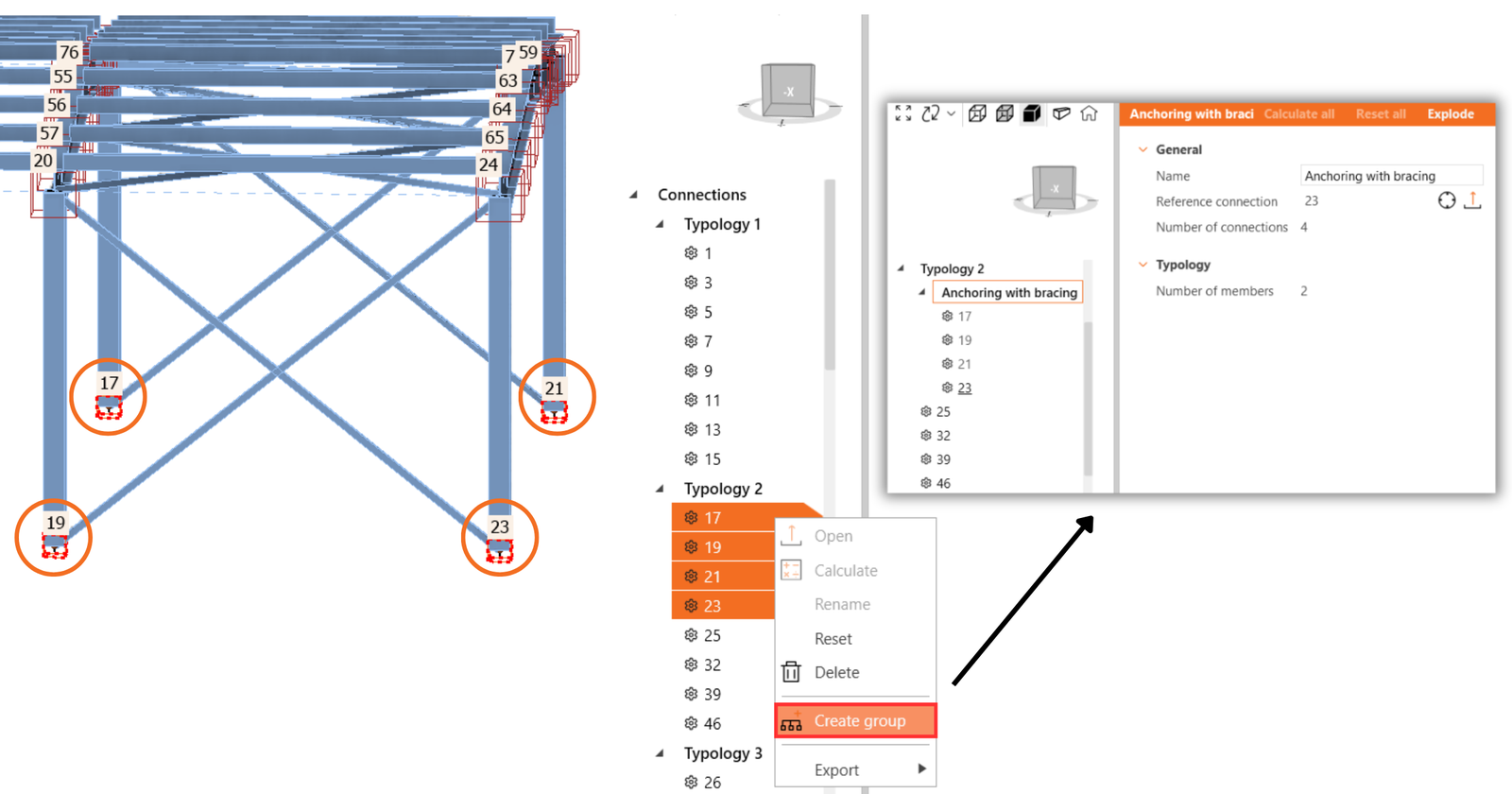
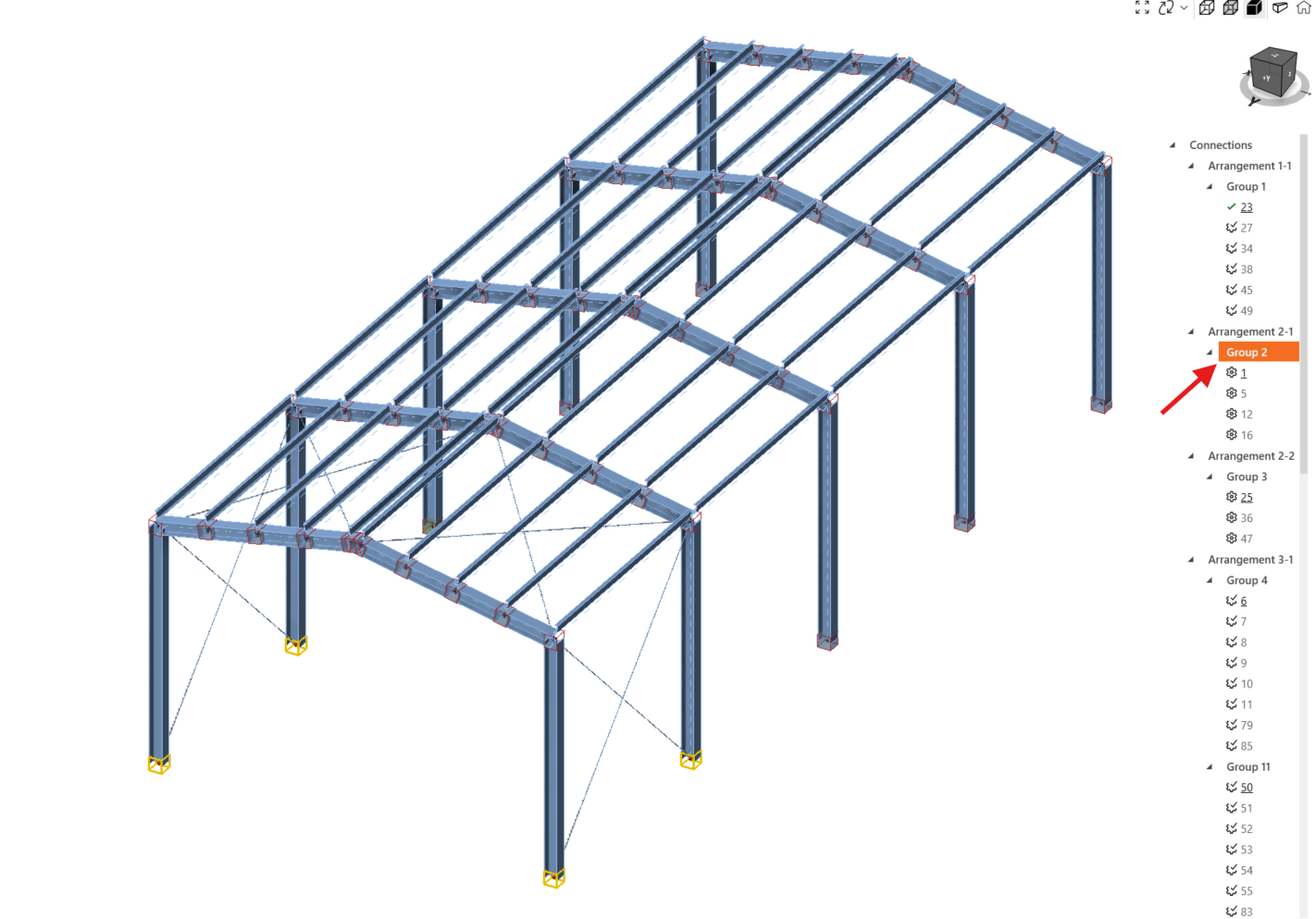
Funcționalitatea de grupare creează automat grupuri pe baza tipologiei și/sau secțiunilor transversale. Grupurile sunt apoi ordonate de la cel mai puțin complex la cel mai complex, în funcție de numărul de elemente conectate. Fiecare grup este reprezentat de îmbinarea de referință (subliniată în arbore), care funcționează ca îmbinarea părinte ce ghidează proiectarea pentru întregul grup. Toate celelalte îmbinări sunt tratate ca îmbinări secundare.
- Îmbinarea de referință (cea subliniată) - aici creați proiectarea și setările pentru îmbinare
- Îmbinările secundare (toate celelalte din grup) - editarea este dezactivată, proiectarea și setările sunt preluate din îmbinarea de referință
Orice operații adăugate la îmbinarea de referință vor fi duplicate automat la îmbinările secundare pentru a evita munca repetitivă, inclusiv setările proiectului, poziția încărcării și tipul modelului. Ajustarea îmbinărilor secundare este dezactivată. Dacă sunt necesare ajustări, faceți clic dreapta pe îmbinare și selectați Eliminați din grup. Odată ce o îmbinare este degrupată, toate operațiile copiate din îmbinarea de referință vor fi, de asemenea, șterse.
Îmbinarea de referință este aleasă în timpul importului ca primul nod selectat pentru grupul dat în modelul structural global, și NU pe baza celor mai mari încărcări din grup. Îmbinările secundare pot avea încărcări mai mari decât îmbinarea de referință.
Pentru a schimba îmbinarea de referință, trebuie să desfaceți grupul, să creați un grup nou cu singura îmbinare dorită ca referință și apoi să atribuiți restul îmbinărilor acestui grup.
Grupuri definite de utilizator
În plus, utilizatorii pot crea propriile grupuri, permițând o personalizare suplimentară și organizarea pe baza nevoilor specifice ale proiectului.
Pentru a defini o îmbinare specifică ca referință, începeți prin crearea unui grup care include doar îmbinarea de referință dorită. Odată creat grupul cu o singură îmbinare de referință, adăugați celelalte îmbinări la grup. Puteți selecta mai multe îmbinări și le puteți schimba grupul cu un singur clic.
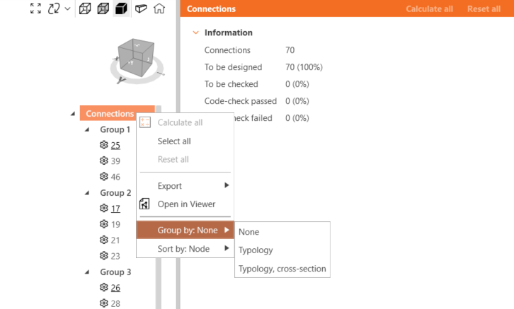
Grupare în arbore
Niciuna aranjează îmbinările doar în funcție de grupuri.
Gruparea după Tipologie ia în considerare numărul de elemente și pozițiile lor relative (grindă-grindă, grindă-stâlp). Nu ia în considerare rotația elementelor. Grupurile dinamice sunt, de asemenea, luate în considerare.
Gruparea după Tipologie, secțiune transversală (Aranjament) diferențiază grupurile tipologice în funcție de tipurile de secțiuni transversale proiectate. De exemplu, un HEB 200 și un HEB 220 se află sub același tip de secțiune transversală. Gruparea după tipologie și aranjament este setată implicit. Grupurile dinamice sunt, de asemenea, luate în considerare.
Lansat în IDEA StatiCa versiunea 25.0.
Alinierea elementelor după secțiunea transversală
Acesta este un pas necesar între modelul global importat din software-ul FEA, unde geometria este simplificată, și modelul de proiectare bazat pe CAD în IDEA StatiCa Connection, unde geometria corespunde proiectării reale.
Selecția individuală, selecția multiplă sau selecția de zonă permit utilizatorilor să introducă eficient excentricitățile locale și globale și să alinieze elementele pentru a le potrivi suprafețele în întregul model structural importat în Checkbot.
Puteți introduce excentricități pentru unul sau mai multe elemente simultan. Selectați sistemul de coordonate Local sau Global și introduceți excentricitatea pozitivă sau negativă pentru punctul de început și punctul de sfârșit al elementului în direcția X, Y sau Z.
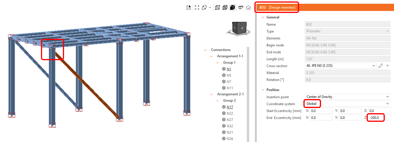
Pentru a alinia elementele, selectați elementele care trebuie aliniate împreună și alegeți opțiunea Punct de inserție, pentru a alinia, de ex., la suprafața superioară, centrul de greutate, suprafața stângă etc.
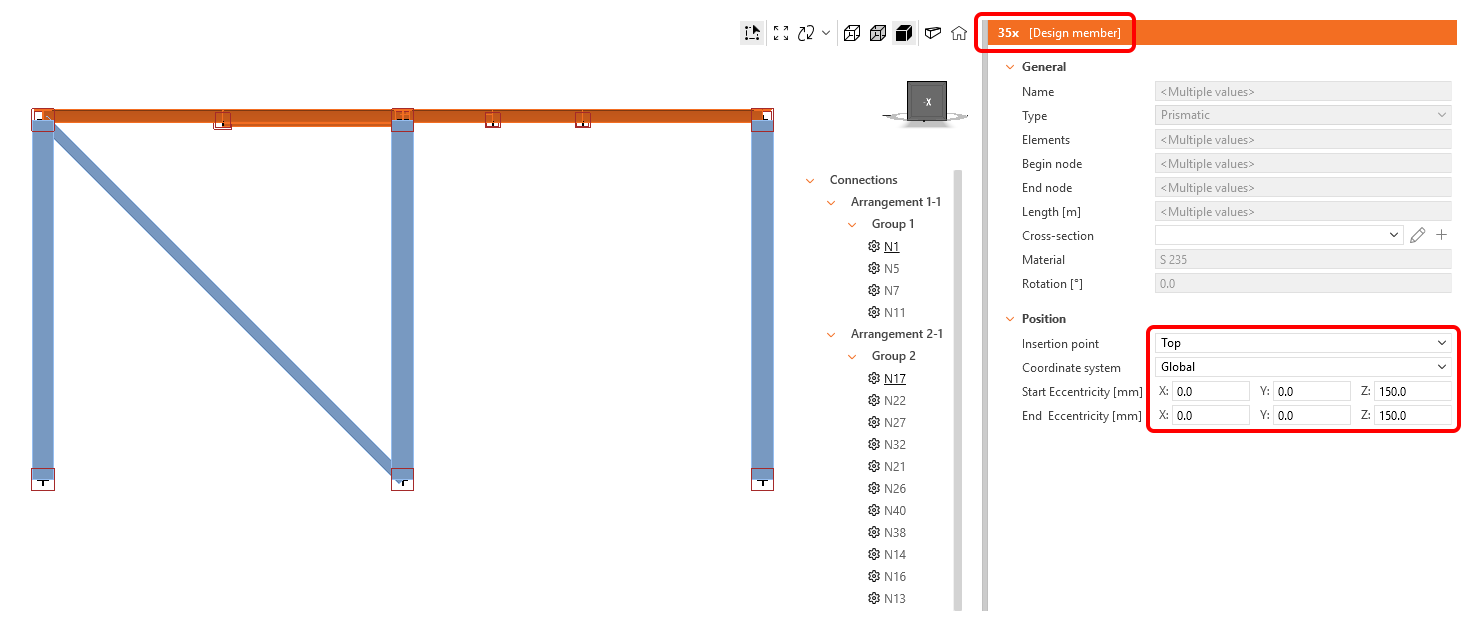
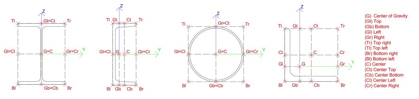
Punctul de inserție permite selectarea mai multor puncte pe secțiunea transversală a elementului. Programele FEA utilizează de obicei abrevieri pentru punctele de inserție, care sunt traduse în lista Checkbot după cum urmează:
| G | Centrul de greutate | Tr | Dreapta sus | C | Centru |
| Gt | Sus | Tl | Stânga sus | Ct | Centru sus |
| Gb | Jos | Br | Dreapta jos | Cb | Centru jos |
| Gl | Stânga | Bl | Stânga jos | Cl | Centru stânga |
| Gr | Dreapta | Cr | Centru dreapta |
Notă: Eforturile interioare nu sunt actualizate odată cu alinierea sau excentricitatea adăugată. Aceasta poate duce la generarea de momente încovoietoare suplimentare în elementele afectate ca urmare a modificării dispoziției geometrice. Pentru a preveni acest lucru, alinierea și excentricitățile trebuie setate corespunzător în modelul global FEA înainte de importul în Checkbot.
Această funcție poate fi limitată pentru software-ul FEA unde legătura BIM cu IDEA StatiCa este dezvoltată de producătorul FEA sau de o terță parte – verificați lista integrărilor suportate.
Lansat în IDEA StatiCa versiunea 25.1.
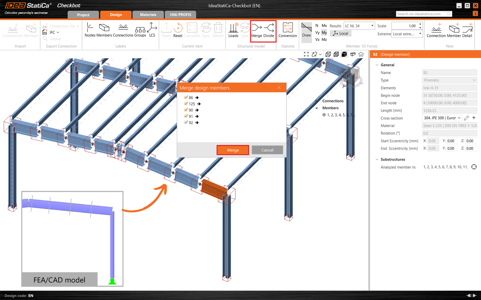
Îmbinarea elementelor
În unele cazuri, în modelul software de analiză, un element poate fi împărțit în mai multe elemente, dar în realitate este un element continuu. Pentru aceste cazuri, funcționalitatea Îmbinare poate corecta acest lucru. Faceți clic dreapta pe unul dintre elementele împărțite pe care doriți să le îmbinați și bifați celelalte elemente pe care doriți să le conectați. Vă rugăm să rețineți că doar elementele aliniate de-a lungul aceluiași vector X pot fi îmbinate.
În plus, dacă trebuie să anulați o îmbinare, butonul Divizare vă permite să separați orice elemente care au fost deja îmbinate înapoi în starea lor originală.
Îmbinarea îmbinărilor
Configurațiile de îmbinare cu mai multe noduri structurale apropiate care ar trebui analizate într-un singur model de îmbinare (un singur rost) pot fi importate ca două îmbinări separate, apărând de obicei pentru diagonale excentrice.
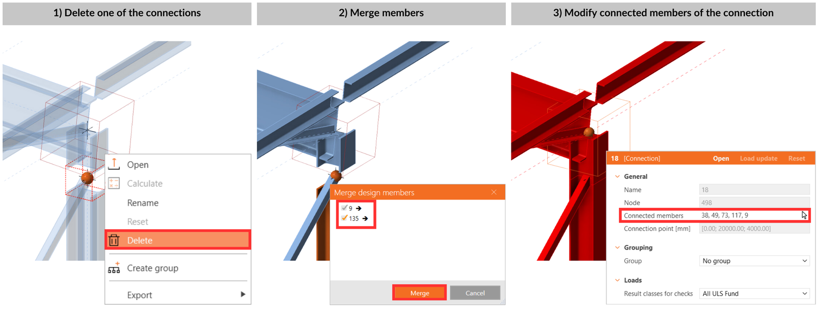
Prin clic dreapta pe caseta din scena 3D sau selectându-le în lista arborescentă, ștergeți toate elementele de îmbinare (noduri structurale) reprezentate de casete goale, cu excepția unuia. Adăugați toate elementele aparținând unei singure îmbinări folosind pictograma săgeată de lângă parametrul Elemente de îmbinare (selectat evidențiat în roșu).
Manager de îmbinări
Pentru o prezentare organizată a proiectului, Checkbot oferă un status rezumat al proiectului care afișează numărul total de îmbinări, câte mai trebuie proiectate și numărul celor verificate. De asemenea, arată câte îmbinări au trecut sau au picat verificarea conform codului, oferind utilizatorilor o vedere cuprinzătoare a progresului proiectului dintr-o privire.
Pentru a accesa prezentarea generală, faceți clic pe Îmbinări în arbore și toate datele vor fi afișate.
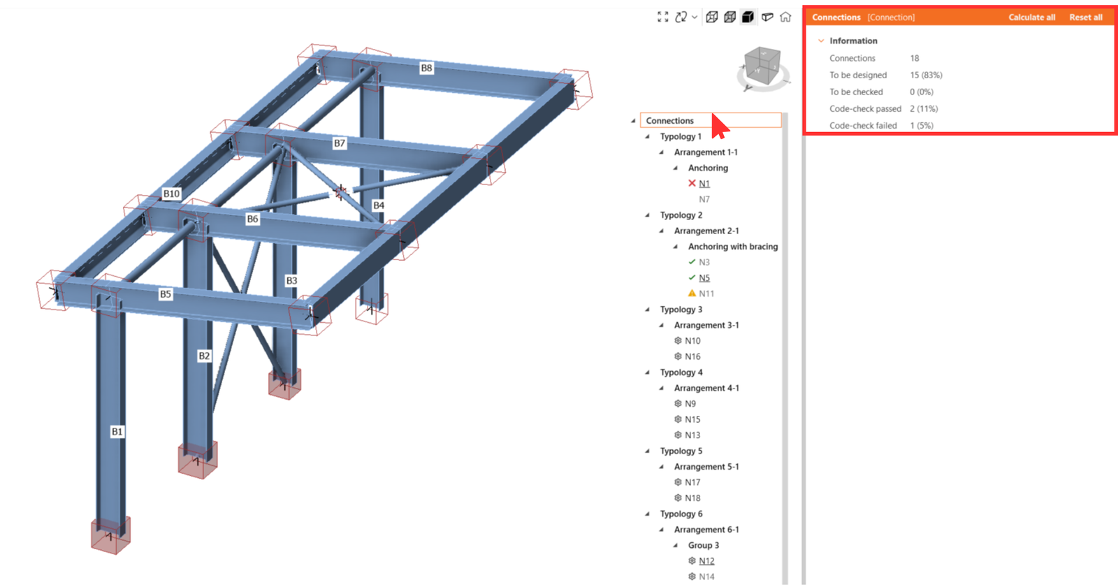
În plus, fiecare îmbinare este marcată cu următoarele pictograme pentru a oferi o prezentare rapidă.
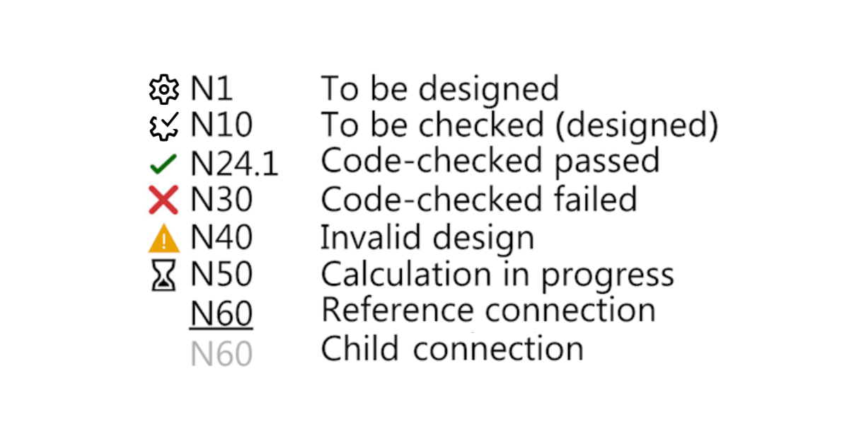
- Roată dințată – neproiectată
- Roată dințată cu bifă – pregătită pentru calcule
- Bifă verde – calculată și verificările conform codului au trecut
- Cruce roșie – calculată, dar verificările conform codului au eșuat
- Proiectare invalidă – la sincronizarea sau actualizarea modelului structural, îmbinarea secundară nu mai îndeplinește parametrul îmbinării de referință. Este necesară actualizarea proiectării sau o potențială regrupare.
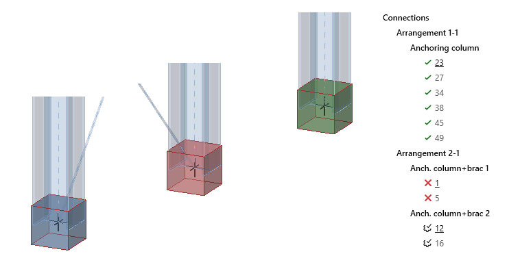
Culorile casetelor în scena 3D
Un element de îmbinare selectat este evidențiat cu un cadru portocaliu în scena 3D. Toate îmbinările legate de același grup al îmbinării selectate sunt evidențiate cu un cadru galben.
Starea îmbinării este vizibilă nu doar în lista arborescentă, după cum s-a menționat mai sus, ci și direct în scena 3D, și este reprezentată prin următoarele culori:
- niciuna - de proiectat
- albastru - pregătită pentru calcul
- verde - calculată și verificările conform codului au trecut
- roșu - calculată, dar verificările conform codului au eșuat
Lansat în IDEA StatiCa versiunea 25.0.
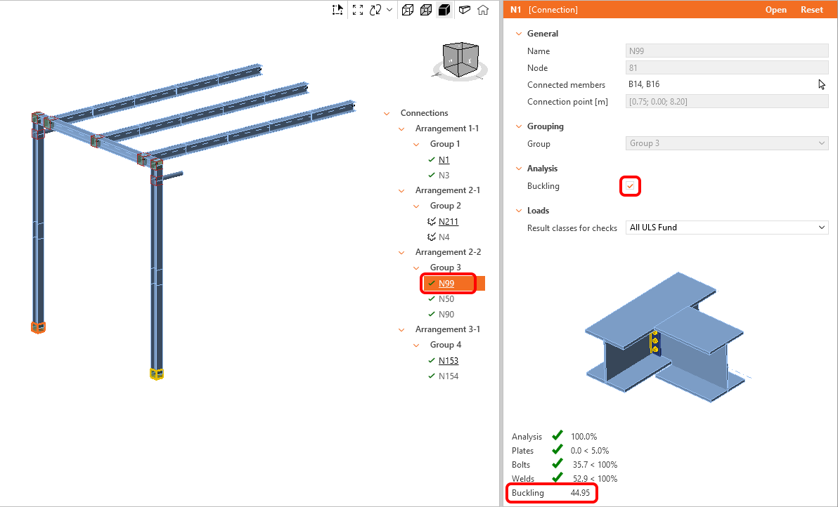
Calculul analizei de flambaj pentru toate îmbinările
Analiza de flambaj poate fi calculată în masă pentru grupurile de îmbinări selectate. În mod implicit, analiza de flambaj este dezactivată. Pentru a activa analiza de flambaj, selectați Îmbinarea de referință și bifați caseta combinată Flambaj.
Cel mai mic factor de flambaj este afișat în fila de rezultate generale din fereastra Checkbot și este adăugat și în raport.
Lansat în IDEA StatiCa versiunea 25.1.
Lucrul simultan cu Checkbot și fereastra Connection
În special când lucrați pe computere cu două monitoare, odată ce fereastra aplicației Connection este deschisă din Checkbot, nu o închideți. Reveniți pur și simplu la aplicația Checkbot și deschideți un alt element de îmbinare. Fereastra Connection se va reîncărca rapid. Aceasta este mult mai rapid decât închiderea și deschiderea ferestrei Connection pentru fiecare element de îmbinare revizuit.
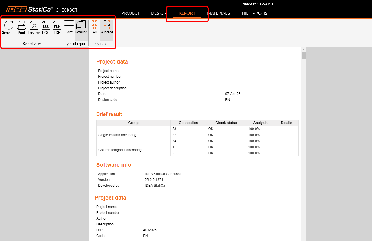
Raport în masă
Raportul poate fi generat pentru toate îmbinările din proiect simultan sau doar pentru îmbinările selectate. Nivelul de detaliu, numărul de capitole incluse și notele suplimentare scrise de mână cu imagini pot fi ajustate în fila Raport. Modul de ajustare a raportului este explicat în acest articol.
Partajarea proiectelor Checkbot
Partajarea proiectelor permite utilizatorilor să distribuie proiectele Checkbot direct prin e-mail sau link URL.
Un proiect poate fi partajat folosind comanda Partajare din bara de instrumente. În timpul procesului, utilizatorii pot:
- Alege să includă rezultatele (afectează dimensiunea fișierului)
- Adăuga unul sau mai mulți destinatari
- Revizui cota de stocare în cloud disponibilă
Odată inițiat, încărcarea rulează în fundal chiar dacă Checkbot este închis. Procesul poate fi monitorizat în Windows Task Manager (colțul din dreapta jos al barei de activități). Odată ce încărcarea se finalizează sau este întreruptă, apare o notificare Windows. Încărcările incomplete pot fi eliminate manual sau sunt șterse automat după o perioadă definită. Toți destinatarii primesc un e-mail automat cu acces la proiectul partajat.
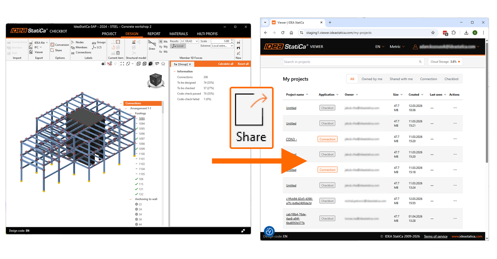
Proiectele partajate sunt încărcate în stocarea cloud și pot fi gestionate în IDEA StatiCa Viewer sub meniul Proiectele mele (sub autentificare în colțul din dreapta sus), care oferă o prezentare generală a tuturor fișierelor încărcate și partajate. Utilizatorii pot căuta și filtra proiecte, copia un link URL către proiecte, revizui detaliile de partajare și șterge proiecte.
Interfața afișează, de asemenea, utilizarea curentă a stocării și cota disponibilă. Cota depinde de tipul de licență - un cont cu licență standard are 10 GB de spațiu pentru toți utilizatorii săi de licență, un cont cu licență Enterprise are 100 GB, iar utilizatorii individuali Basic/Trial au 500 MB.
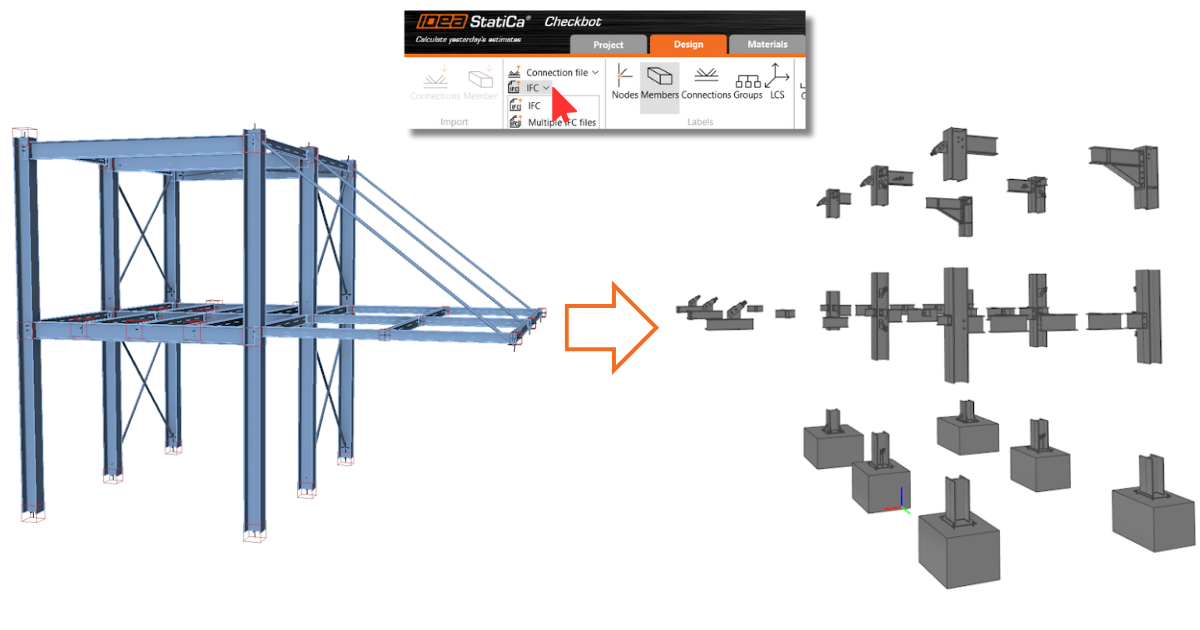
Export în IFC
Formatul Industry Foundation Classes (IFC) este un format de date deschis, neutru față de furnizori, care permite partajarea datelor. Checkbot vă permite să exportați toate îmbinările selectate într-un singur model IFC sau să exportați îmbinările în fișiere IFC individuale într-un folder specific.
Exportul conține coordonatele globale ale Punctului de îmbinare – locația reală a unei îmbinări într-un proiect.
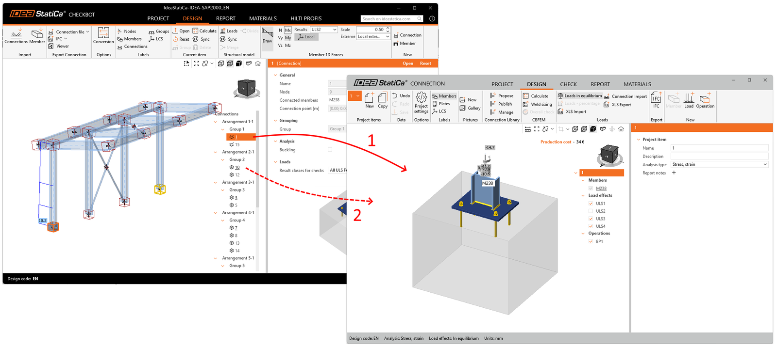
Export în Connection
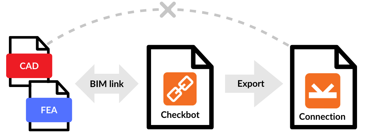
Când Checkbot este conectat la software-ul terților printr-o legătură BIM, nu vă permite să editați geometria și proprietățile elementelor, editarea este dezactivată. Dacă astfel de modificări sunt necesare, puteți exporta orice element de îmbinare din Checkbot într-un singur fișier IDEA StatiCa Connection și puteți edita fiecare parte a modelului. Puteți exporta o singură îmbinare sau selecta mai multe îmbinări simultan.
Fișierul Connection exportat individual este independent de proiectul Checkbot. Prin urmare, nu mai este posibilă nicio sincronizare ulterioară cu modelul structural FEA sau gestionarea acestuia în Checkbot.
Lansat în IDEA StatiCa versiunea 25.0.
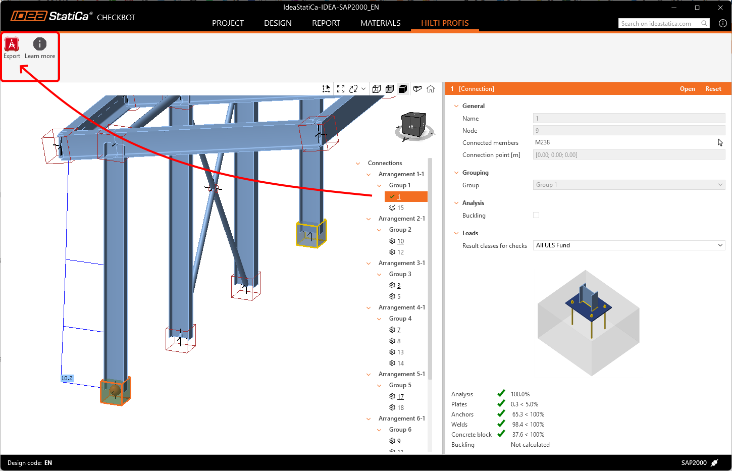
Export în Hilti PROFIS Engineering
Hilti PROFIS Engineering Suite este un software ușor de utilizat, bazat pe cloud, pentru proiectarea și analiza ancorelor. Prin selectarea unui nod cu un singur element ancorat, utilizatorii pot exporta datele direct în Hilti PE folosind butonul Export , asigurând transferul precis al datelor structurale relevante pentru analize ulterioare.
Acest flux de lucru complet este disponibil chiar și cu o licență Basic IDEA StatiCa, ceea ce înseamnă că este disponibil gratuit. Modul de utilizare a plugin-ului este descris pas cu pas în următorul articol, accesibil și din butonul Aflați mai multe din Checkbot.
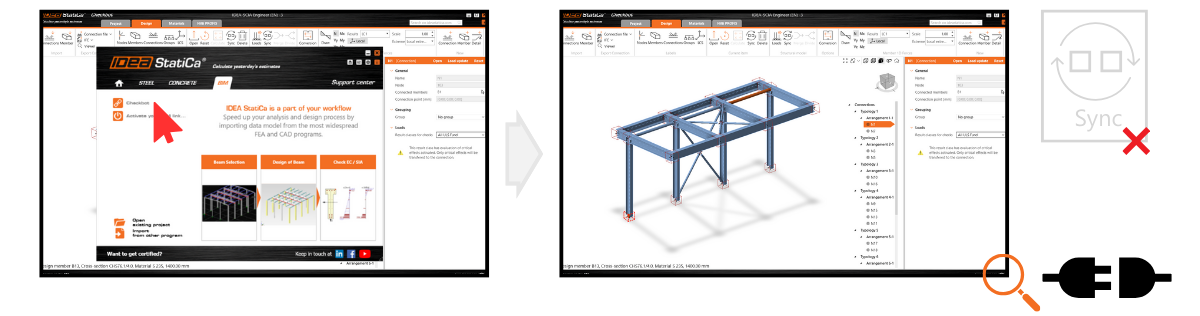
Sincronizare
După importul tuturor elementelor necesare, butonul Sincronizare vă permite să detectați și să aplicați cu ușurință modificările din proiectul sursă în modelul IDEA StatiCa. Aceste modificări pot include actualizări ale grosimilor, secțiunilor transversale sau modificări ale proprietăților sudurilor și șuruburilor. Cu toate acestea, este important de reținut că actualizările nu pot include componente noi sau șterse, cum ar fi plăci, elemente, elemente repoziționate sau combinații de încărcări. În astfel de cazuri, trebuie să ștergeți proiectul Checkbot curent (folderul) și să îl importați din nou.
Vă rugăm să rețineți că sincronizarea în IDEA StatiCa funcționează într-un singur sens, de la programul sursă la IDEA StatiCa, nu invers.
- Soluție FEA – sincronizarea nu afectează operațiile de proiectare (tăiere, placă de capăt, ...)
- Soluție CAD – sincronizarea nu afectează efectele de încărcare (cu excepția Revit, care poate conține modelul analitic cu rezultate)
Dacă ulterior sunt efectuate modificări în modelul software terț, trebuie să redeschideți proiectul Checkbot și să apăsați butonul Sincronizare pentru a vă asigura că toate actualizările din modelul software terț sunt reflectate în Checkbot. Butonul de sincronizare este activat doar dacă fișierul Checkbot este deschis prin aplicația terță.
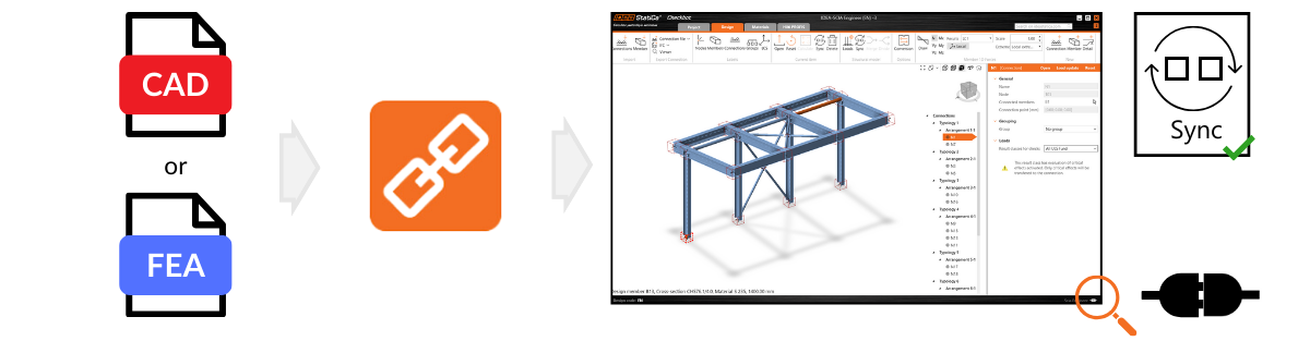
Rețineți că butonul Sincronizare este activ doar dacă Checkbot este deschis din modelul FEA sau CAD original, nu separat. Dacă mutați, redenumiți sau manipulați în alt mod folderul Checkbot creat lângă fișierul FEA sau CAD, conexiunea de date se pierde și Sincronizarea nu mai este disponibilă.
Rețineți că orice modificări efectuate direct în IDEA StatiCa (de ex., la secțiuni transversale, excentricități, combinații de încărcări sau operații) vor fi suprascrise în timpul sincronizării cu proiectul sursă. Aceeași regulă se aplică dacă excentricitățile sunt modificate în IDEA StatiCa.
De exemplu, dacă ajustați un proiect de îmbinare în IDEA StatiCa Connection care a fost inițial importat din Tekla Structures și apoi sincronizați, modificările dvs. din IDEA StatiCa vor fi înlocuite de cele mai recente date de proiectare din Tekla Structures.
Lansat în IDEA StatiCa versiunea 25.0, actualizat în IDEA StatiCa versiunea 25.1.