
Projeto paramétrico no IDEA StatiCa Connection - Ligação tubular
Criar modelo
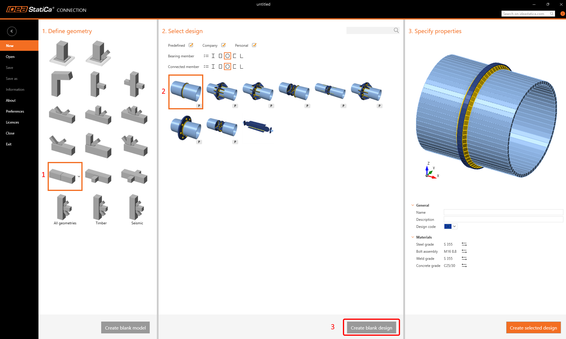
Inicie a aplicação Connection e escolha o seguinte modelo e parâmetros iniciais (clique em Blank design):
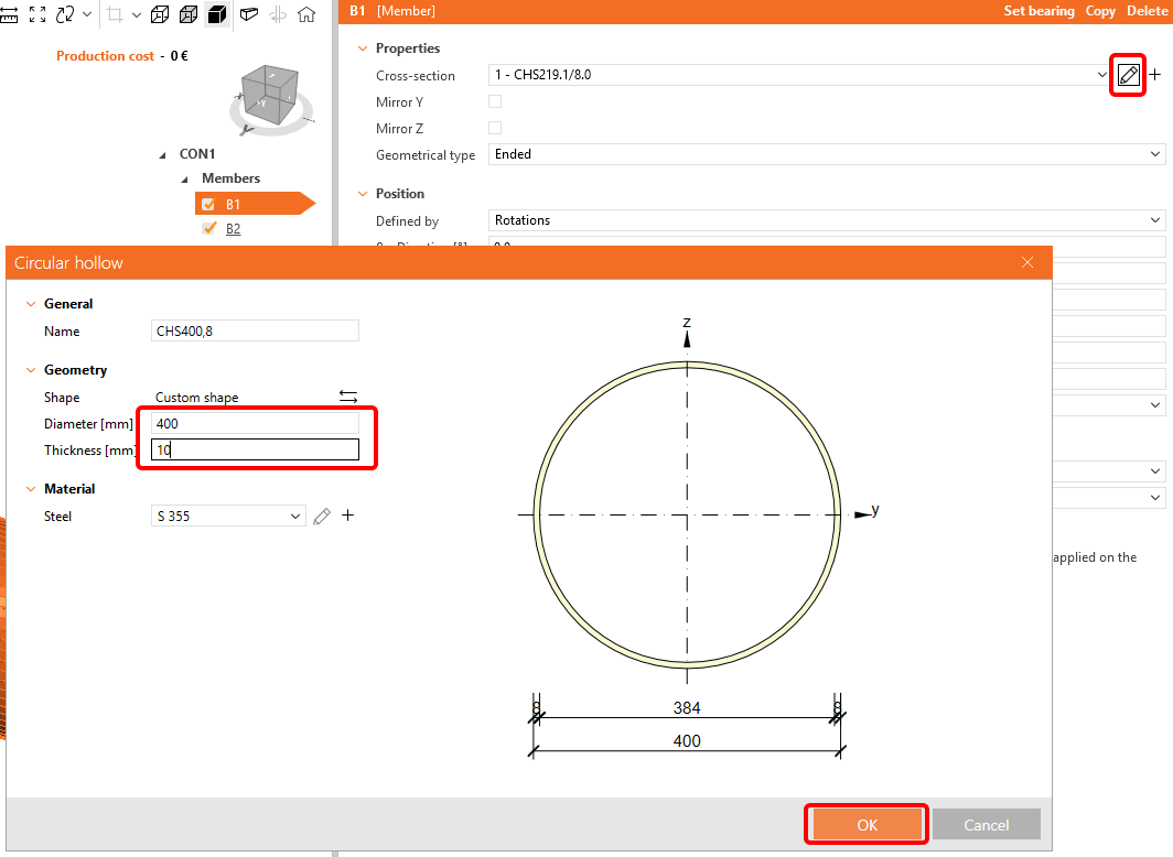
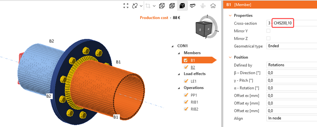
Altere as dimensões da secção transversal para B1 e B2 para d = 400 mm e t = 10 mm:
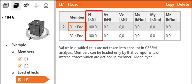
Aceda a LE1 e modifique conforme indicado:
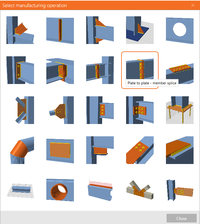
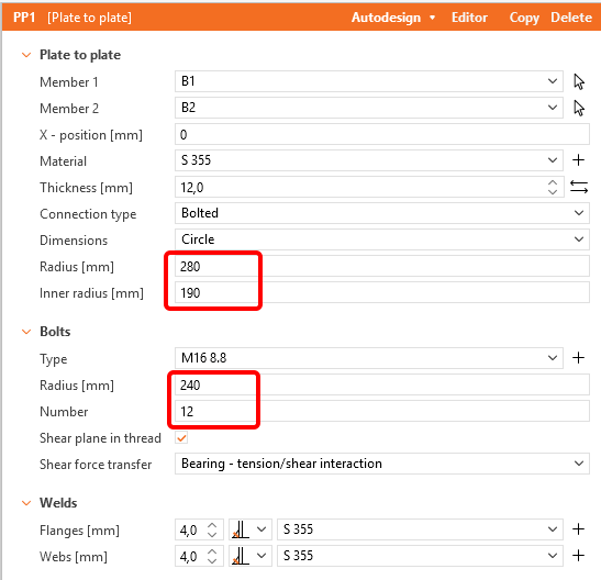
Adicione uma nova operação Plate to Plate e altere os valores de acordo com a imagem:
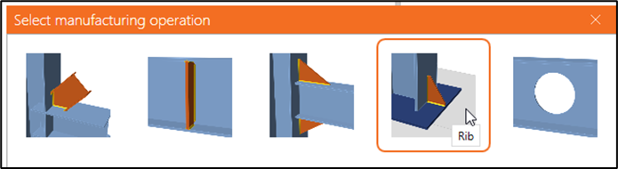
Adicione uma nova operação Rib ao elemento B1 e PP1a:

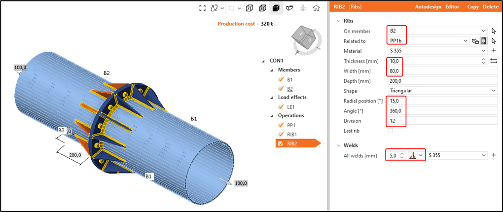
Copie a operação RIB1 para criar RIB2 e aplique-a a B2 e PP1b:
O modelo inicial está agora concluído. Parece um modelo bastante simples com poucas operações e não há nada de errado com isso. No entanto, observe quanto tempo demora a criar uma variante diferente da ligação em que:
- Diâmetro do tubo = 350 mm
- Número de parafusos = 8
- Comprimento das nervuras = 175 mm (metade do diâmetro do tubo)
O raio interior do flange circular deve coincidir com o raio interior do tubo, enquanto o raio exterior deve permanecer 80 mm maior do que o raio exterior dos tubos. As nervuras devem estar sempre posicionadas a meio caminho entre os parafusos.
Como poderá ter notado, embora pareça uma modificação rápida, pode demorar alguns minutos a modelar 1 nova variante. Se pretender modelar muitas variantes mais rapidamente, esta abordagem pode consumir demasiado tempo.
Separador Developer
Para acelerar o processo, iremos tornar o modelo paramétrico e criar um modelo paramétrico. Para isso, aceda a:
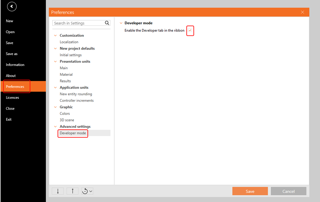
Separador Project -> Preferences -> Advanced settings -> Developer mode e ative o separador Developer:
Criar parâmetros e modelo paramétrico
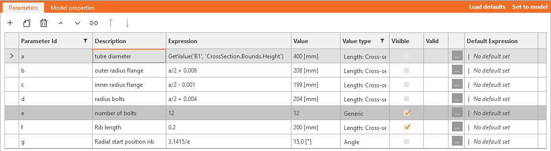
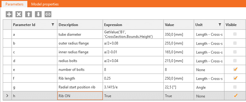
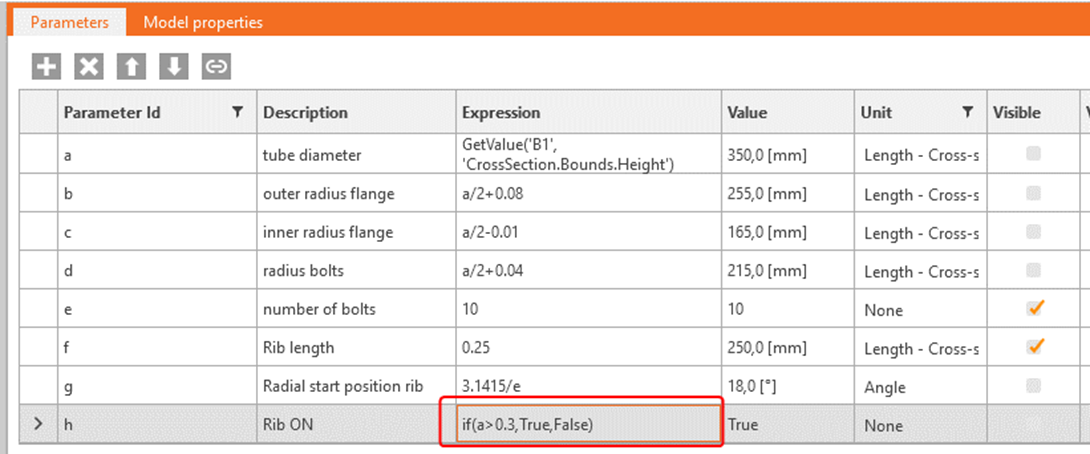
Aceda ao separador Developer e crie 7 novos parâmetros, atribuindo-lhes um Id de parâmetro de "a" a "g". Cada parâmetro pode receber uma descrição e uma expressão. Desta forma, determinados parâmetros podem ser tornados dependentes uns dos outros. Defina a unidade correta para cada parâmetro:
| a | diâmetro do tubo | GetValue('B1', 'CrossSection.Bounds.Height') |
| b | raio exterior do flange | a/2 + 0.08 |
| c | raio interior do flange | a/2 - 0.01 |
| d | raio dos parafusos | a/2 + 0.04 |
| e | número de parafusos | 12 |
| f | comprimento da nervura | 0.2 |
| g | posição radial inicial da nervura | 3.1415/e |
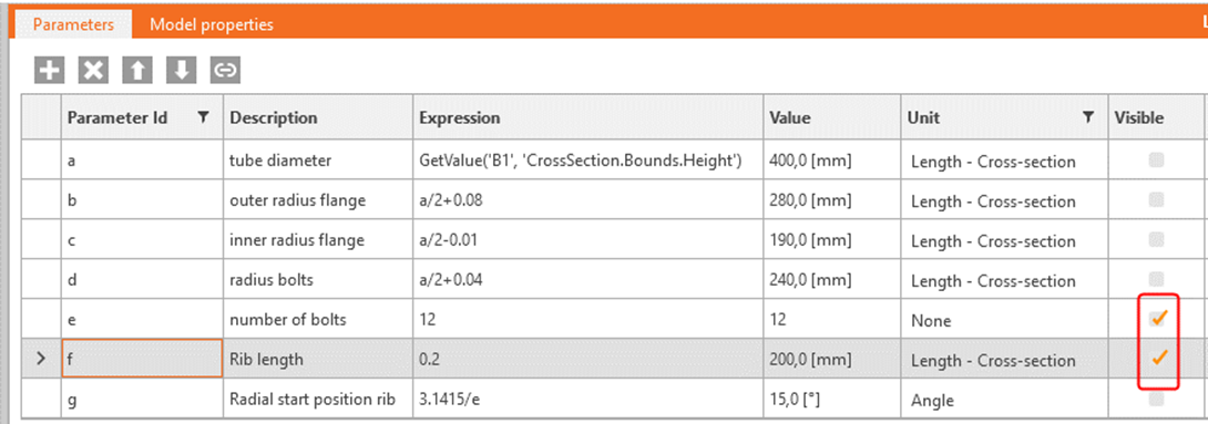
Para criar um modelo paramétrico, escolha os parâmetros que pretende que sejam definidos pelo utilizador (a e e) e defina-os como Visible:
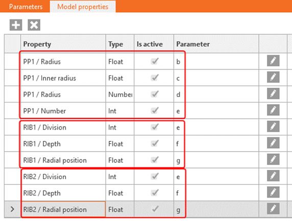
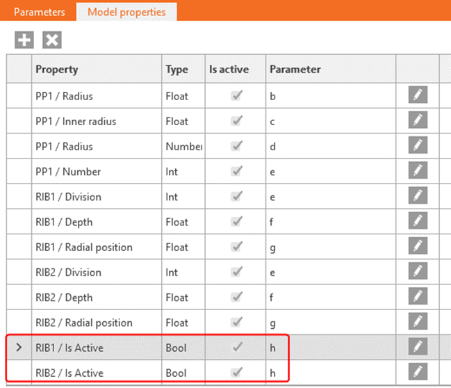
Agora atribua os parâmetros relevantes às propriedades específicas do modelo:
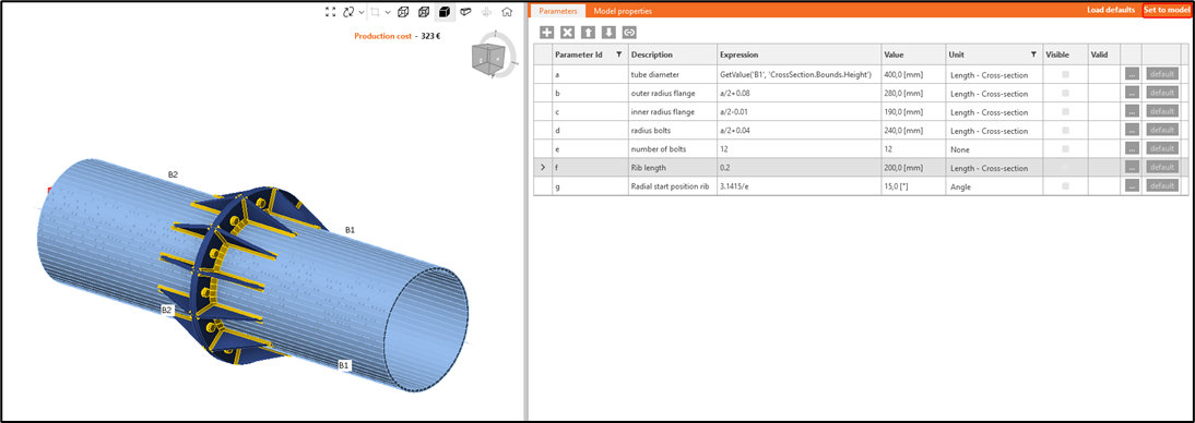
Clique em "Set to model" e observe como a ligação se altera com base nos parâmetros de entrada:
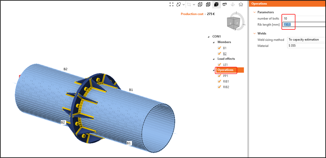
Volte ao separador Design e clique em Operations. Aí encontrará os parâmetros que foram definidos como visíveis. Pode alterar os parâmetros e premir Enter, e o modelo será atualizado em conformidade.
Também pode utilizar operadores booleanos. Crie um novo parâmetro h com a descrição "Rib ON" e atribua-lhe como expressão "True". Defina-o também como Visible:
Associe este parâmetro à propriedade do modelo RIB1 / Is Active e RIB2 / Is Active:
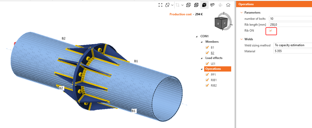
Observe a diferença ao ativar e desativar no modelo paramétrico:
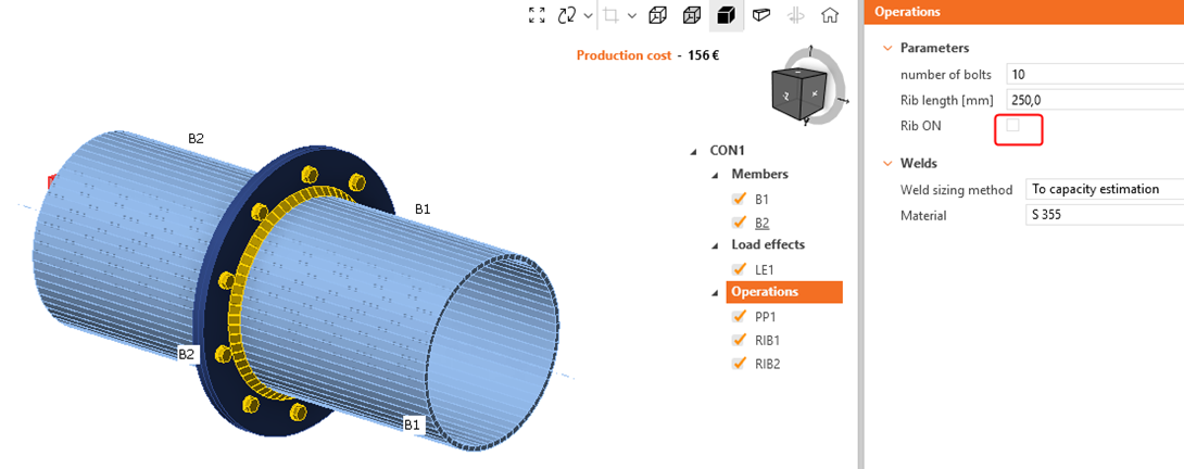
Uma alternativa é utilizar instruções if/then na expressão:
| h | Rib ON | if(a>0.3,True,False) |
A escolha de um diâmetro menor para o tubo < 300 mm deverá desativar as nervuras:
Veja abaixo o modelo concluído.
Com este tutorial, adquiriu as competências necessárias para utilizar parâmetros e realizar tarefas fundamentais relacionadas com parâmetros.
Transferências Anexadas
- tubular.ideaCon (IDEACON, 126 kB)