O dimensionamento de ligações pode ser difícil de ensinar, dada a natureza detalhada do tema e o comportamento fundamentalmente tridimensional da maioria das ligações. No entanto, as ligações são de importância crítica, e as lições aprendidas no estudo do dimensionamento de ligações, incluindo o percurso de carga e a identificação e avaliação dos modos de rotura, são gerais e aplicáveis ao dimensionamento estrutural em sentido lato. A IDEA StatiCa utiliza um modelo de análise não linear rigoroso e dispõe de uma interface de fácil utilização com visualização tridimensional dos resultados (por exemplo, configuração deformada, tensão, deformação plástica), sendo assim particularmente adequada para a exploração do comportamento de ligações de aço estrutural. Com base nestes pontos fortes, foi desenvolvido um conjunto de exercícios guiados que utilizam a IDEA StatiCa como laboratório virtual para ajudar os estudantes a aprender conceitos sobre o comportamento e dimensionamento de ligações de aço estrutural. Estes módulos de aprendizagem foram direcionados principalmente a estudantes de licenciatura avançada e de pós-graduação, mas foram também adaptados para engenheiros em exercício de funções. Os módulos de aprendizagem foram desenvolvidos no Laboratory for Numerical Structural Design pelo Professor Assistente Martin Vild da Brno University of Technology.
Objetivo de Aprendizagem
Após a realização deste exercício, o formando deverá ser capaz de descrever o componente básico das ligações aparafusadas, o T-stub, e os fenómenos associados, como a força de alavanca.
Enquadramento
O método das componentes da EN 1993-1-8 divide a ligação em componentes. O componente básico das ligações aparafusadas, amplamente utilizado em juntas de montagem, é o T-stub. A forma do T-stub varia consoante a sua localização na ligação, mas o cálculo mantém-se muito semelhante. Mesmo uma ligação com placa de extremidade com mísula tão complexa é dividida em oito filas de T-stubs. Cada T-stub é calculado individualmente ou como parte de um grupo de parafusos, e a resistência última ao momento é a soma da resistência à tração do T-stub multiplicada pelo braço de alavanca em relação ao centro de compressão.

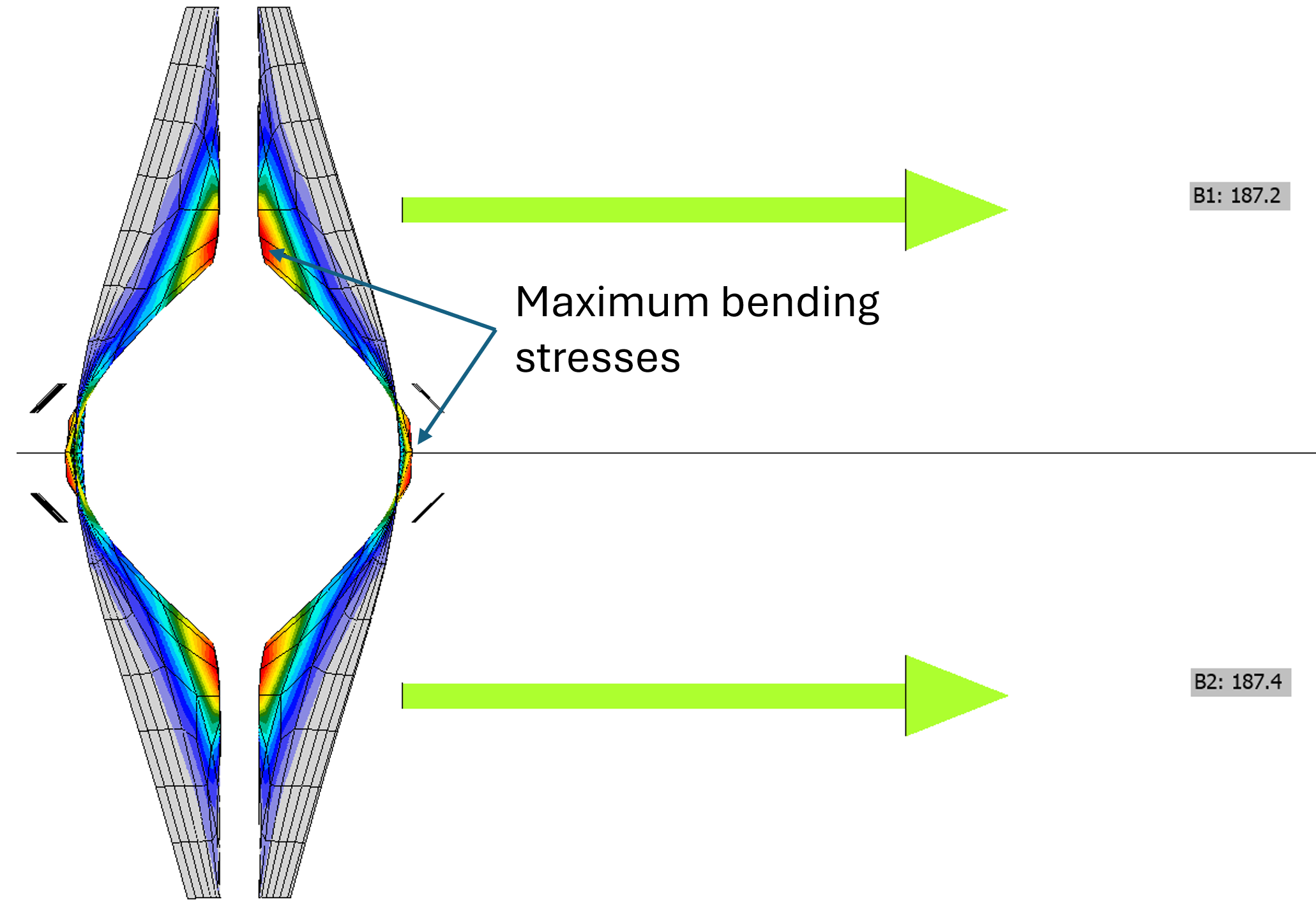
Uma característica típica dos T-stubs é a força de alavanca. A soma da tração nos parafusos é superior à tração aplicada ao T-stub. Isto é causado pela força de alavanca – uma ação de apoio das chapas sobre o suporte, tipicamente outro T-stub, neste caso constituído pelo banzo e pela alma do pilar. Note-se que a soma das forças de tração nos parafusos na figura seguinte é \(2 \cdot 187.2 = 374.4\) kN, o que é significativamente superior aos 193 kN da força aplicada.
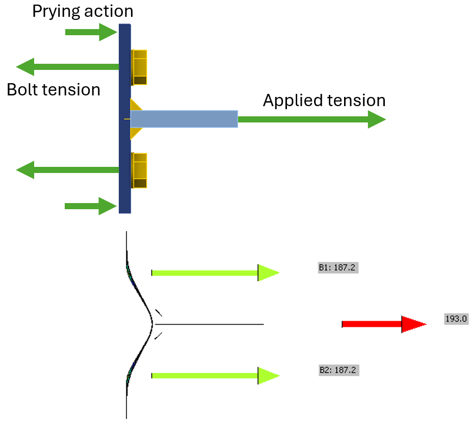
A magnitude da força de apoio depende da rigidez e da resistência dos elementos ligados e dos parafusos.
- Se a placa de extremidade for muito fina, plastificará tanto junto à soldadura como junto à linha de parafusos, e a resistência da placa de extremidade será condicionante mesmo considerando a tração adicional nos parafusos devida à força de alavanca. O Eurocódigo descreve isto como modo de rotura 1.
- Se a placa de extremidade for muito espessa, não se curvará o suficiente para superar o alongamento do parafuso, e a placa de extremidade não entrará em contacto com o banzo do pilar. Neste caso, não existe força de alavanca, a resistência dos parafusos será condicionante, e uma análise simples é suficiente para estimar a força nos parafusos. O Eurocódigo descreve isto como Modo 3.
- Para espessuras de placa de extremidade entre estes extremos, a resistência à flexão das cantoneiras e a resistência à tração dos parafusos podem ser condicionantes em simultâneo.
No Eurocódigo 3 (CEN, 2005), estes diferentes comportamentos são designados por "Modo 1: Plastificação completa do banzo"; "Modo 2: Rotura dos parafusos com plastificação do banzo"; e "Modo 3: Rotura dos parafusos", correspondendo a elementos de ligação finos, intermédios e espessos, respetivamente.
As equações para avaliar a força de alavanca estão incluídas no Eurocódigo EN 1993-1-8, Cl. 6.2.4. Estas equações podem ser utilizadas para avaliar eficientemente a força de alavanca, mas recorrem a parâmetros abstratos que obscurecem o comportamento físico. Este exercício tem como objetivo ajudar a desenvolver a intuição física sobre a força de alavanca.
Ligação
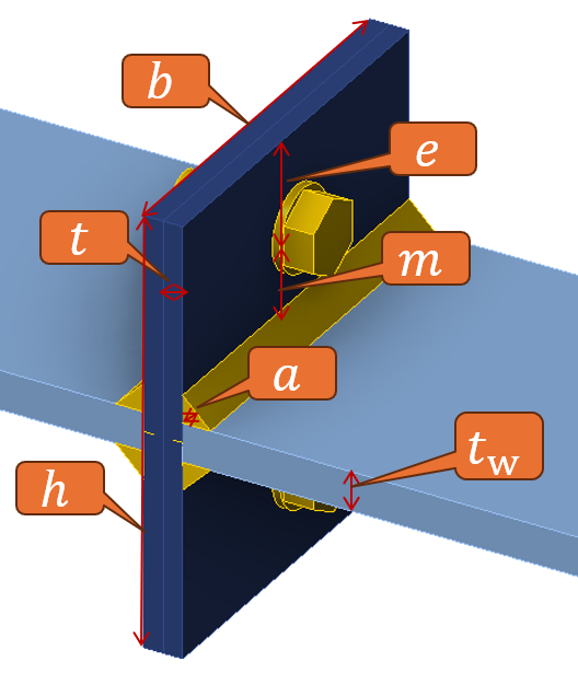
A ligação examinada neste exercício é o exemplo básico de dois T-stubs idênticos orientados costas com costas. O caso básico consiste em duas placas de extremidade (ou banzos de T-stub) com as dimensões \(b \cdot h = 200 \cdot 220\) mm e espessura de \(t = 20\) mm. As chapas tracionadas (ou almas de T-stub) têm 20 mm de espessura. Todos os elementos são em aço de grau S355. Soldaduras de filete duplas com espessura de garganta de 10 mm ligam as almas dos T-stubs aos banzos. Os banzos dos T-stubs são ligados por parafusos M24 8.8 (\(d = 24\) mm, \(f_u = 800\) MPa). Os parafusos estão no centro do T-stub e a sua distância à extremidade é \(e = 50\) mm.
Procedimento
O procedimento para este exercício pressupõe que o formando possui conhecimentos práticos sobre a utilização da IDEA StatiCa (por exemplo, como navegar no software, definir e editar operações, realizar análises e consultar resultados). Orientações sobre como adquirir esses conhecimentos estão disponíveis no site da IDEA StatiCa (https://www.ideastatica.com/).
Obtenha o ficheiro IDEA StatiCa para a ligação de exemplo fornecida com este exercício. Abra o ficheiro na IDEA StatiCa. Para realizar o exercício, siga a narrativa, complete as tarefas e responda às questões.
O formando dispõe de dois ficheiros auxiliares:
- T-stub calculation-Calcpad.zip – um cálculo manual em Calcpad de código aberto
- T-stub.py – um código Python para a automatização da IDEA StatiCa através da sua API
A execução destes ficheiros não é obrigatória para completar o módulo de aprendizagem, mas acelera o cálculo manual.
1. Calcule a resistência de cálculo à tração de um único parafuso M24 8.8, o tipo de parafuso utilizado na ligação.
2. Calcule a resistência de cálculo à tração da ligação assumindo que a resistência dos parafusos é condicionante e sem força de alavanca.
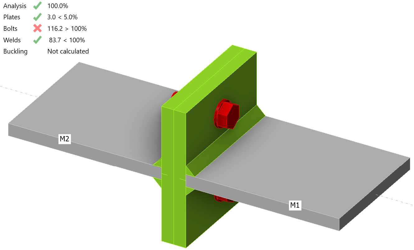
3. Com a espessura da chapa de aba definida para 20 mm, aplique a carga determinada no passo 2 à ligação no IDEA StatiCa e execute uma análise. A ligação consegue suportar a carga?
Não. A análise atinge apenas 90,2% desde que a opção Parar no estado limite esteja ativada nas Definições do projeto.

A utilização máxima dos parafusos é de 116,2% desde que a opção Parar no estado limite esteja desativada.
4. Se a ligação não conseguir suportar a carga, determinar a carga máxima que a ligação consegue suportar.
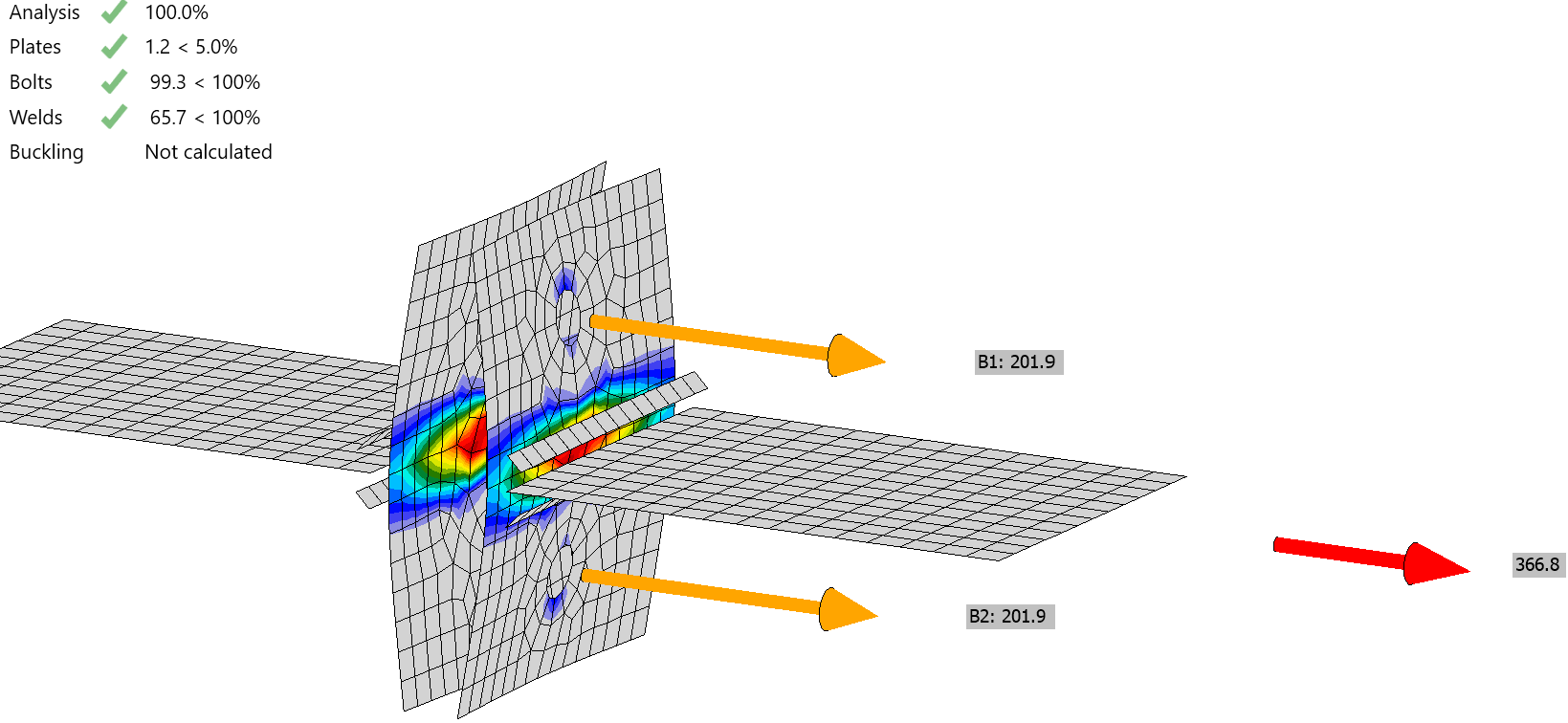
5. Na carga máxima que a ligação consegue suportar, qual é a força de tração máxima nos parafusos?
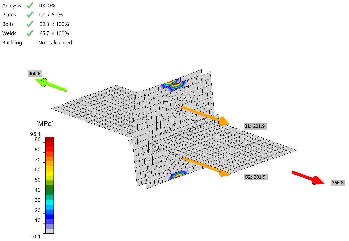
Ambos os parafusos têm 201,9 kN em tração, o que significa que estão no seu limite.
6. Que parte da tração no parafuso pode ser atribuída à força aplicada?
7. Determinar a força de apoio total entre as chapas de banzos. Comparar este valor com a tensão de apoio (ou seja, a tensão nos contactos).
A força de apoio em cada parafuso é 201,9 kN – 183,4 kN = 18,5 kN e 37 kN no total.
A tensão ocorre numa área de aproximadamente 2 × (10 mm) × (40 mm) = 800 mm\(^2\), resultando numa tensão estimada de 37 kN / 800 mm\(^2\) = 46,25 MPa.
A tensão de apoio máxima (ou seja, a tensão nos contactos) é 95,4 MPa. A tensão de apoio média além da linha de parafusos parece ser de cerca de 45 MPa, consistente com a tensão estimada.
8. Esboce a forma deformada da placa de ala e identifique onde as tensões de flexão são maiores.
A placa de ala está em curvatura simples. As maiores tensões de flexão encontram-se na placa de ala junto à chapa de alma.

9. Repita os passos 3 a 8, mas com a espessura da placa de extremidade definida como 10 mm.
A ligação consegue suportar uma carga muito menor com chapas de banzo mais finas.
A força máxima que pode ser transferida através deste T-stub é de 172 kN. A deformação plástica nas chapas de banzo controla agora a resistência. A utilização dos parafusos é de 92%.
Existe em média 187,3 kN nos parafusos, num total de 374,6 kN. 46% é atribuído à força aplicada e 54% às forças de alavanca.
As chapas de banzo estão agora em dupla curvatura. As maiores tensões de flexão encontram-se junto à chapa de alma e nos parafusos.
Complete a tabela apresentada abaixo determinando a força máxima que a ligação consegue suportar para diversas espessuras de chapa de banzo, registando depois essa força juntamente com a deformação plástica máxima e a utilização máxima dos parafusos para essa força.
| Espessura da chapa de banzo [mm] | Força máxima [kN] | Deformação plástica máxima [%] | Utilização dos parafusos [%] |
| 8 | 123.0 | 4.16 | 90.9 |
| 10 | |||
| 12 | 228.5 | 4.87 | 97.4 |
| 14 | 283.2 | 4.03 | 99.5 |
| 16 | 312.5 | 1.90 | 99.4 |
| 18 | 337.9 | 1.40 | 99.3 |
| 20 | |||
| 22 | 400.4 | 1.20 | 99.8 |
| 24 | 408.2 | 0.32 | 99.6 |
| 26 | 408.2 | 0.11 | 99.6 |
| 28 | 408.2 | 0.05 | 99.6 |
| 30 | |||
| 32 | 408.2 | 0.00 | 99.6 |
| 34 | 408.2 | 0.00 | 99.6 |
| 36 | 408.2 | 0.00 | 99.6 |
| 38 | 408.2 | 0.00 | 99.6 |
| 40 |
10. O que observa sobre estes resultados?
A resistência da ligação aumenta, diminui ou mantém-se igual quando as seguintes dimensões são aumentadas? Considere de que forma a resposta pode ser diferente para diferentes espessuras de chapa de banzo.
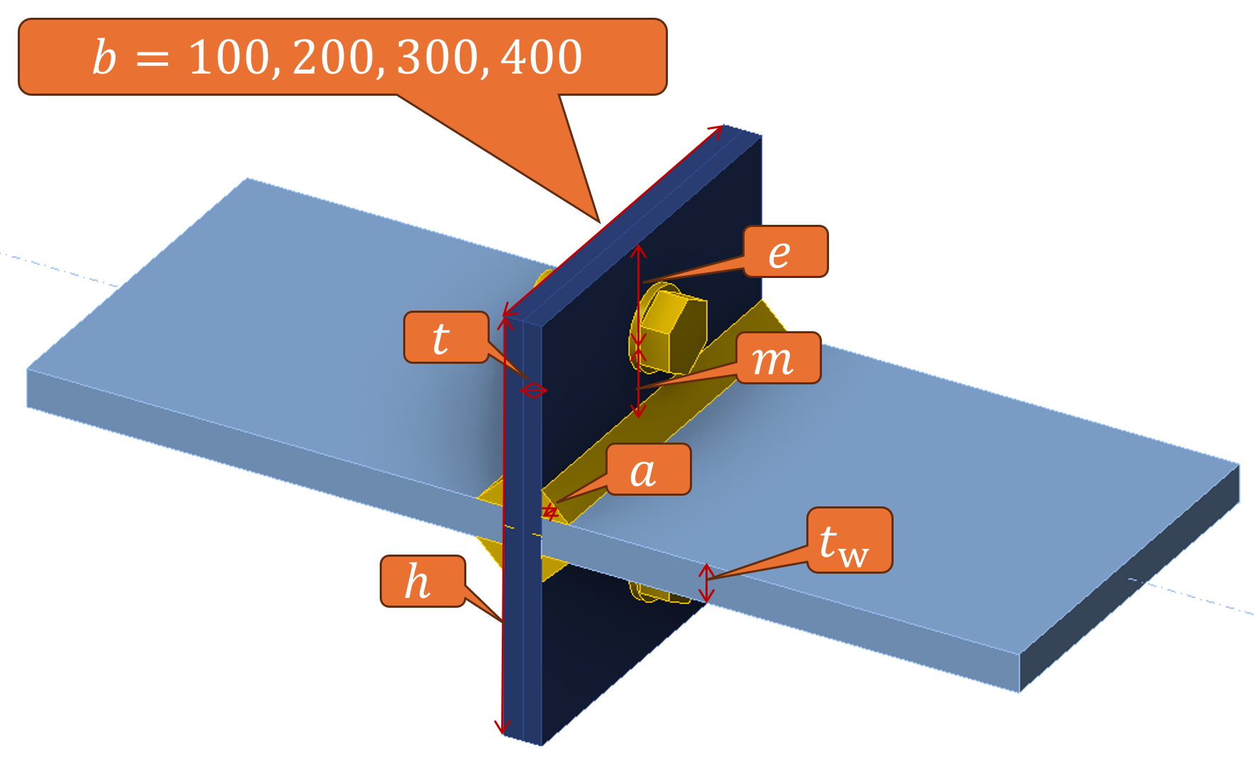
11. A largura do T-stub
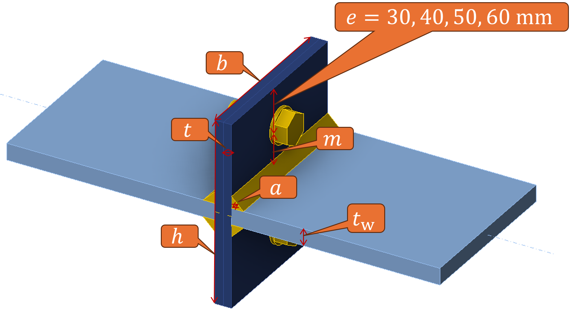
12. A distância das linhas de parafusos à extremidade da chapa de aba.
13. O diâmetro dos parafusos.
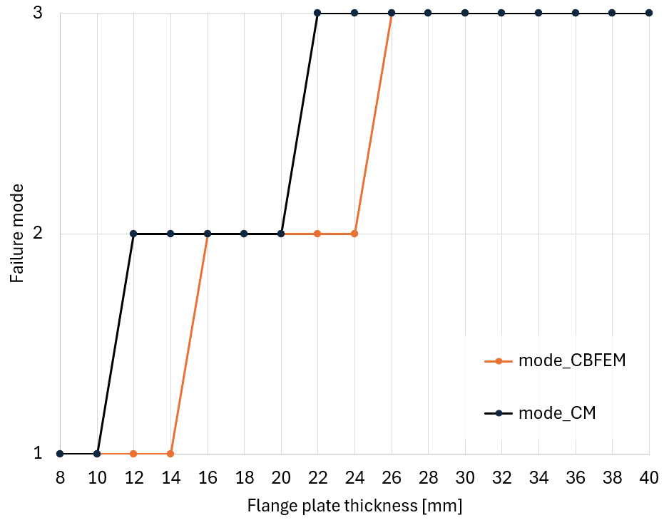
14. Calcule a resistência e o modo de rotura da ligação utilizando as equações equivalentes do T-stub em EN 1993-1-8 (Tabela 6.2) para espessuras de chapa de banzo de 8 a 40 mm. Em que diferem as resistências do IDEA StatiCa e do EC? Quais são as possíveis razões para as diferenças?
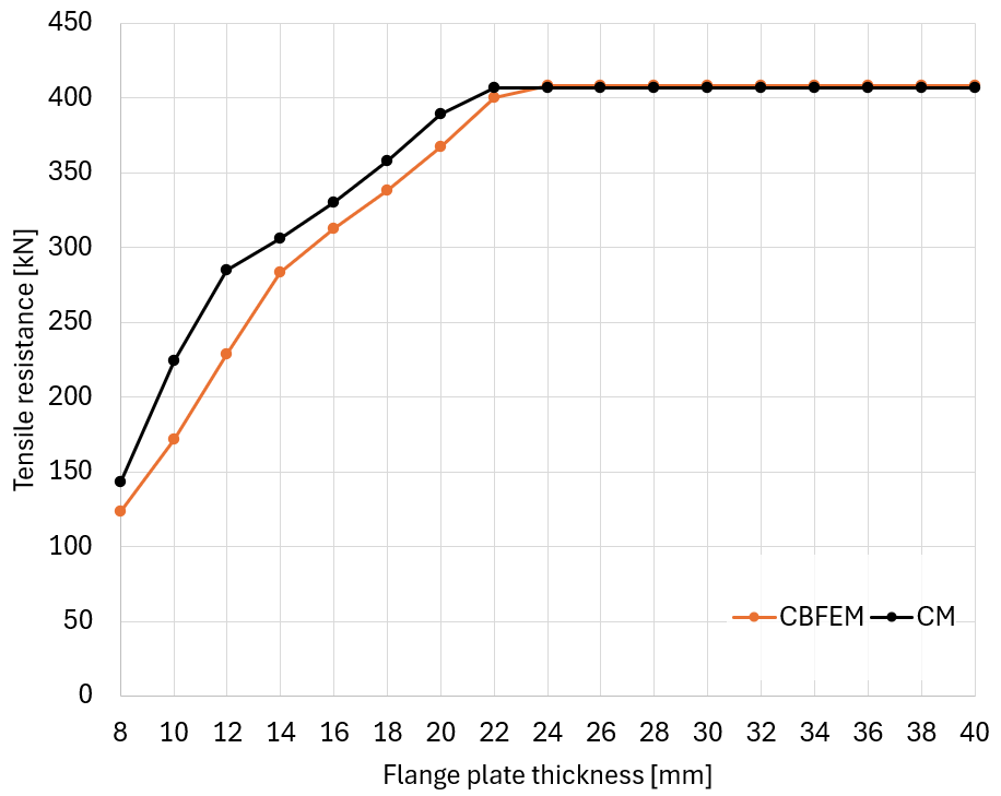
O modo de rotura segundo o CBFEM é estimado pela deformação plástica. Para deformação plástica superior a 3%, é selecionado o modo de rotura 1; para deformação plástica entre 0,3 e 3%, é selecionado o modo de rotura 2. Para deformação plástica muito reduzida, inferior a 0,3%, é selecionado o modo de rotura 3. Isto pode ser estimado com maior precisão observando as linhas de cedência e as forças nos parafusos.
- Modelo de base diferente. As equações do EC baseiam-se num modelo simplificado de comportamento. O IDEA StatiCa utiliza um modelo CBFEM detalhado.
- A linha de cedência no modelo do EC inicia-se atrás das soldaduras, enquanto no IDEA StatiCa as soldaduras distribuem uniformemente a carga, mas não enrijecem a chapa de banzo.
Note-se que o cálculo manual de acordo com a EN 1993-1-8 está bem explicado em SCI P398 nas páginas 10–17.
Referências
EN 1993-1-8:2005 Eurocódigo 3: Dimensionamento de estruturas de aço – Parte 1-8: Dimensionamento de ligações, CEN, Bruxelas
SCI P398 Joints in Steel Construction: Moment-resisting Joints to Eurocode 3, 2013