Tweede-orde effecten in de RCS applicatie
Het ontwerpen van een drukstaaf kan een complexe taak zijn, waarbij rekening moet worden gehouden met talrijke factoren en parameters. Met name imperfecties en tweede-orde effecten kunnen een significante invloed hebben op de maatgevende inwendige krachten, waarmee rekening moet worden gehouden om een veilige en efficiënte constructie te garanderen.
Twee methoden zijn geïmplementeerd in de applicatie:
- Nominale stijfheid
- Nominale kromming
Beide zijn conform EN 1992-1-1 artikelen 5.8.7 en 5.7.8. Het staaftype moet worden ingesteld als Compression Member om toegang te krijgen tot de functionaliteit.
Voor meer informatie over staaftypes die kunnen worden ingesteld in de applicatie, zie het artikel Doorsnede- en staaftypes in de RCS applicatie.
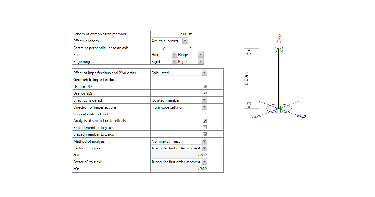
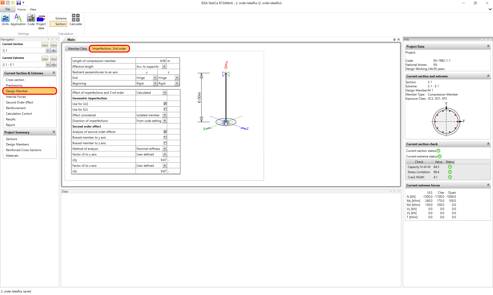
Zodra uw doorsnede is aangemaakt, belast en voorzien van wapening, gaat u naar de Navigator -> Design Member en selecteert u Imperfections, 2nd order. Hier kunt u de kniklengte en alle parameters instellen die nodig zijn voor de berekening van de maatgevende inwendige krachten.
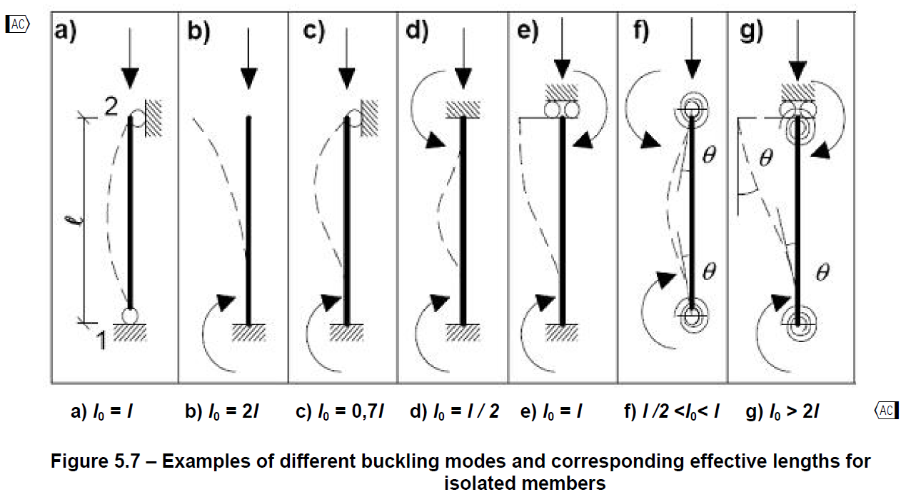
De kniklengte kan automatisch worden berekend op basis van de opleggingsomstandigheden loodrecht op de "y"-as of de "z"-as. Dit gebeurt conform EN 1992-1-1 Figuur 5.7, waarbij l0 de Length of the compression member is in de applicatie.
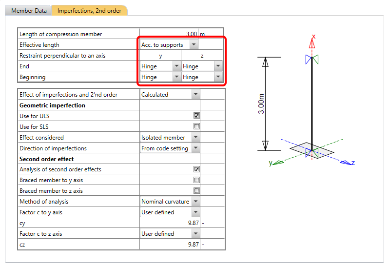
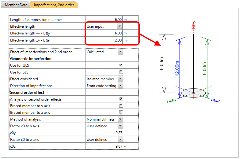
Of, als u de kniklengte al kent, kunt u deze instellen als gebruikersinvoer.
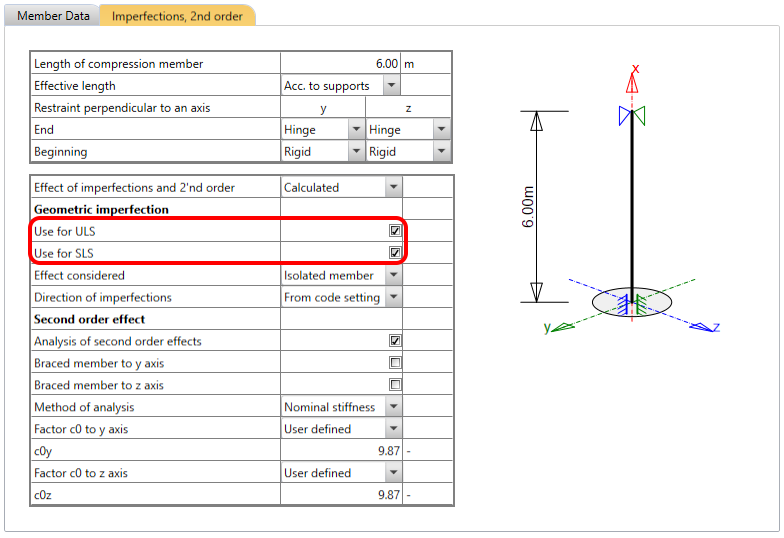
Als u het Effect of imperfections and 2'nd order instelt als Calculated, dient u de parameters voor de geometrische imperfectie en het tweede-orde effect in de tabel in te stellen.
Laten we de instellingen doorlopen en er meer over leren.
Geometrische imperfectie
De geometrische imperfectie wordt berekend conform EN 1992-1-1 artikel 5.2.
Eerst moet u beslissen of u de imperfectie alleen wilt toepassen voor UGT of BGT, of voor zowel UGT als BGT.
Merk op dat voor BGT alleen de imperfectie ei wordt toegepast. Het is niet nodig om de excentriciteit e2 als gevolg van het tweede-orde effect toe te passen voor BGT conform de norm.
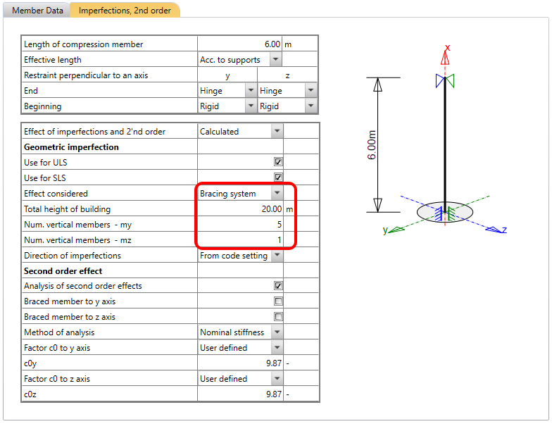
Na het selecteren van de bijbehorende combinatieset dient u de cel Effect considered in te stellen. Er zijn twee opties voor deze functionaliteit:
- Isolated member
- Bracing system
De toelichting is te vinden in EN 1992-1-1 5.2(6).
Conform het betreffende lid van de norm zijn de parameters voor de Isolated member als volgt:
l (lengte) = werkelijke lengte van de staaf
m (aantal verticale staven) = 1
De parameters voor het Bracing system zijn:
l = hoogte van het gebouw
m = aantal verticale staven dat bijdraagt aan de horizontale kracht op het stabiliteitsysteem in beide richtingen
Een andere belangrijke instelling is de Direction of imperfections. Er zijn drie opties:
1. From code setting
Dit betekent dat de optie die is ingesteld in de norminstellingen wordt gebruikt voor de berekening.
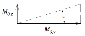
2. Moment resultant
Mi,Ed,y/z = NEd * ei,y/z
waarbij:
NEd is de rekenwaarde van de normaalkracht
ei,y/z is de geometrische imperfectie
Mi,Ed,y/z is het buigend moment als gevolg van de imperfectie
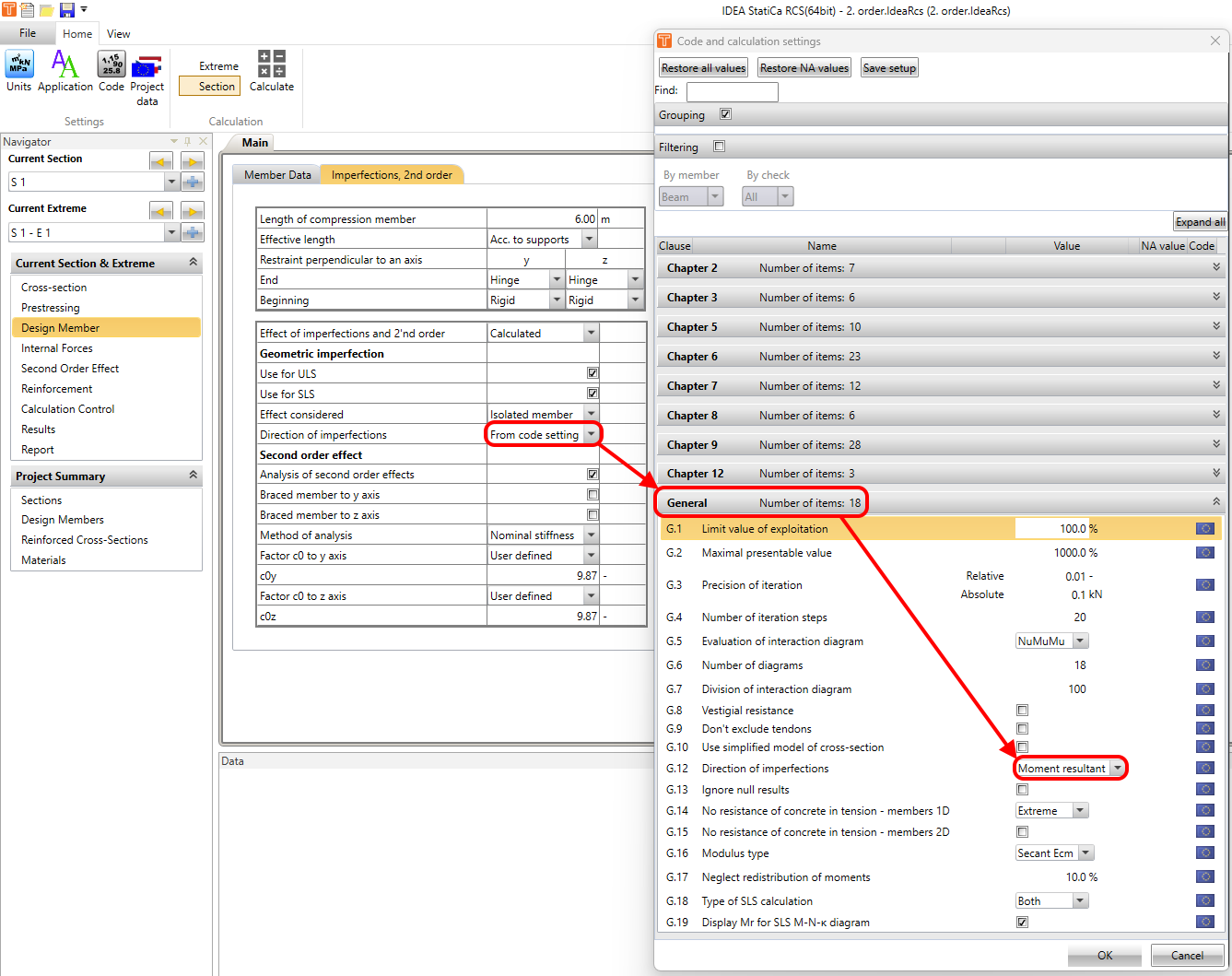
Mi,Ed,y = M0,y + Mi,Ed,y/z * cos (α)
waarbij:
M0,y is het eerste-orde buigend moment om de "z"-as
α is een hoek zoals weergegeven in de onderstaande figuur
Mi,Ed,y is het eerste-orde buigend moment om de "z"-as, inclusief het effect van imperfecties
- Lees het volgende artikel voor meer informatie over Hoe de resulterende eerste-orde excentriciteit op de drukstaaf te berekenen
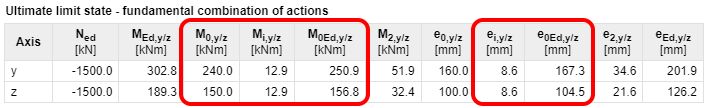
3. Bigger slenderness
Deze optie past de volledige geometrische imperfectie toe in de richting van de grootste slankheid. Zo wordt bijvoorbeeld alleen Mi,Ed,y in beschouwing genomen voor de doorsnede zoals weergegeven in de onderstaande afbeelding.
Tweede-orde effect
In het onderste deel van de tabel kunt u de analyse van tweede-orde effecten instellen. Voordat u de berekeningsmethode kiest, is het noodzakelijk te weten of uw staaf al dan niet geschoord is en in welke richting.
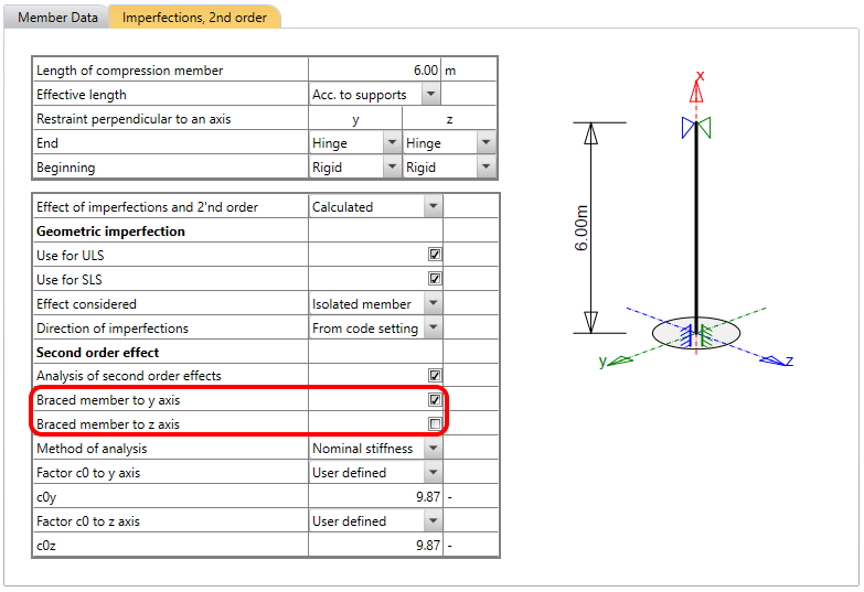
Deze instelling beïnvloedt de berekening van het slankheidscriterium voor geïsoleerde staven conform EN 1992-1-1 artikel 5.8.3.1 (1).
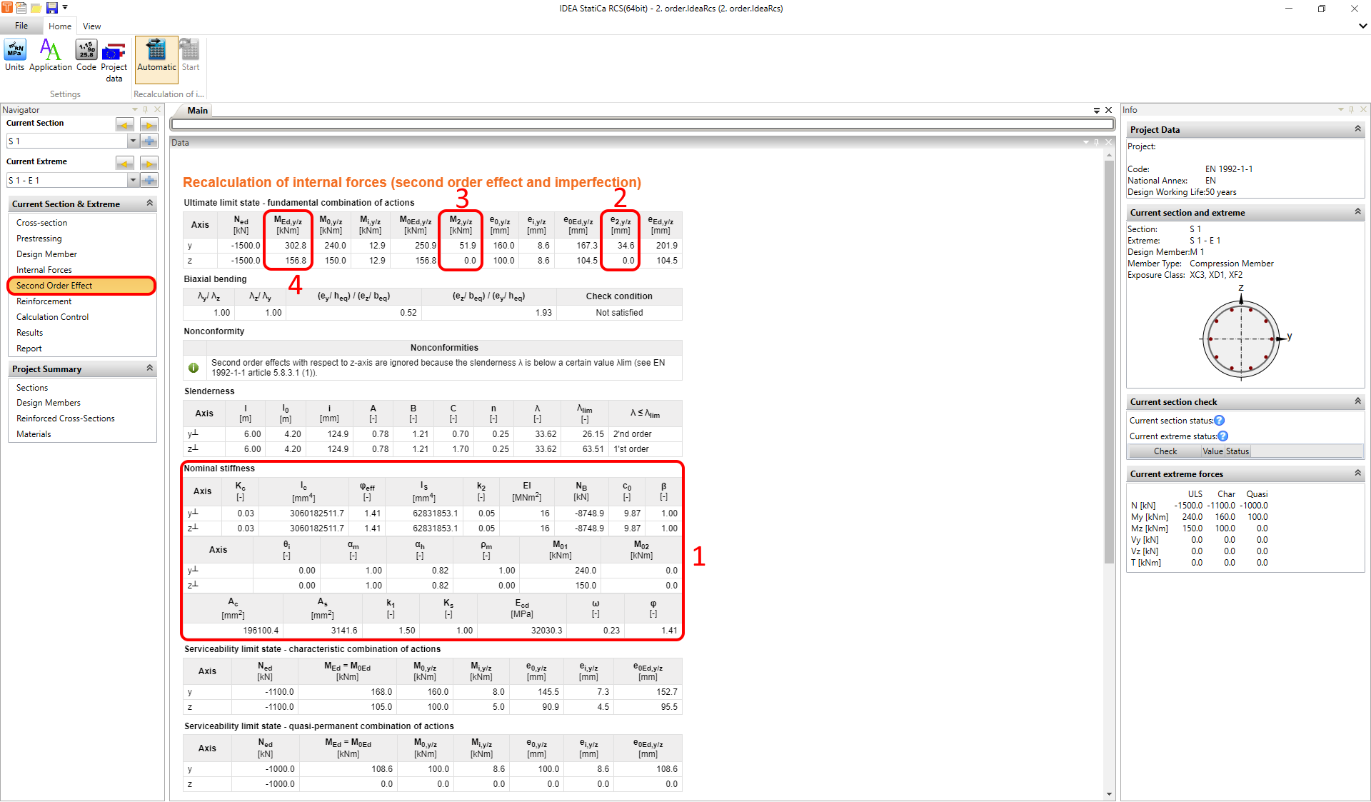
Voor de berekening van de momentverhouding rm factor dient u de eerste-orde eindmomenten M01 en M02 in te stellen. Dit kan worden gedaan in Navigator -> Second Order Effect.
Twee analysemethoden zijn geïmplementeerd in de software:
- Nominale stijfheid
- Nominale kromming
Nominale stijfheid
Voor de nominale stijfheid dient u de factor c0 te definiëren. De beschrijving is te vinden in EN 1992-1-1 artikel 5.8.7.2 (2)(3).
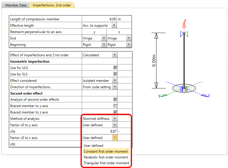
Alle tussenresultaten kunnen worden bekeken in Navigator -> Second Order Effect. Het eindresultaat is het rekenmoment om respectievelijk de "y"- en "z"-as.
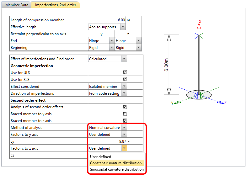
Nominale kromming
Voor de nominale kromming dient u de factor c in te stellen. De beschrijving is te vinden in EN 1992-1-1 artikel 5.8.8.2 (3)(4).
Net als bij de vorige methode kunnen alle tussenresultaten worden bekeken in Navigator -> Second Order Effect. Het eindresultaat is het rekenmoment om respectievelijk de "y"- en "z"-as.
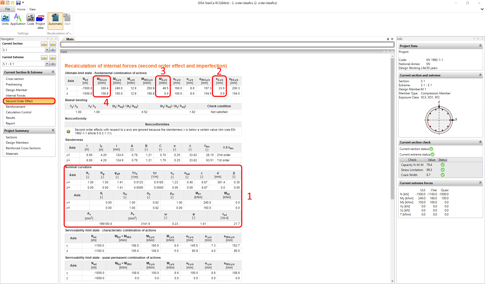
Houd er rekening mee dat voor BGT-controles de aanname MEd = M0Ed geldig is. Dit betekent dat er geen tweede-orde effect is opgenomen voor BGT. Dat wil zeggen dat alleen de imperfecties zijn opgenomen.
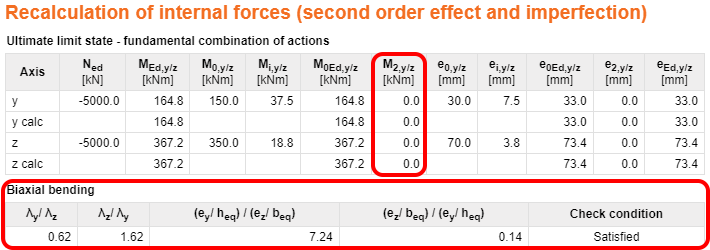
Twee-assige buiging
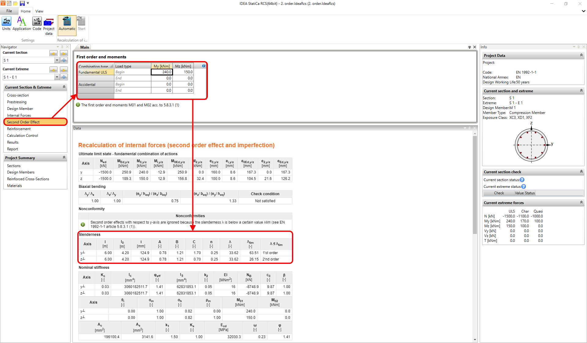
Er is geen verdere controle noodzakelijk als de slankheidsverhouding voldoet aan de twee gemarkeerde voorwaarden in de onderstaande afbeelding.
Dat wil zeggen dat de applicatie het moment M2,y/z niet in beschouwing neemt als aan de controlevoorwaarden is voldaan.