De invoer van interne krachten
De invoer van interne krachten van 2D-staven is afhankelijk van het type 2D-element:
- Shell-slab – membraankrachten (nx, ny en nxy), buigende momenten (mx, my en mxy) en dwarskrachten (vx en vy) kunnen worden ingevoerd
- Shell- wall – membraankrachten (nx, ny en nxy), buigende momenten (mx, my en mxy) en dwarskrachten (vx en vy) kunnen worden ingevoerd
- Slab – alleen buigende momenten (mx, my en mxy) en dwarskrachten (vx en vy) kunnen worden ingevoerd
- Wall – alleen membraankrachten (nx, ny en nxy) kunnen worden ingevoerd
- Deep beam – alleen membraankrachten (nx, ny en nxy) kunnen worden ingevoerd
| Omschrijving | |
| mx(y) | Buigend moment in de richting van de x (y)-as. Een positieve waarde veroorzaakt trek aan het onderoppervlak van een 2D-element. |
| mxy(yx) | Torsiemoment om de y (x)-as werkend op de rand evenwijdig aan de x (y)-as. Een positieve waarde veroorzaakt schuifspanning door trek aan het onderoppervlak van een 2D-element. Omdat in elk punt van het 2D-element de gelijkheid van horizontale schuifspanningen geldt, zijn de torsiemomenten mxy = myx ook in elk punt van het 2D-element gelijk. Daarom wordt alleen de waarde van mxy in het programma ingevoerd. |
| nx(y) | Normaalkracht in de richting van de x (y)-as. Een positieve waarde werkt in de richting van de x(y)-as en veroorzaakt trek in de doorsnede. |
| nxy(yx) | Normaalkracht werkend in het middenvlak in de richting van de y(x)-as op de rand evenwijdig aan de x(y)-as. Een positieve waarde werkt in de richting van de x(y)-as. Omdat in elk punt van het 2D-element de gelijkheid van horizontale schuifspanningen geldt, zijn de normaalkrachten nxy = nyx ook in elk punt van het 2D-element gelijk. Daarom wordt alleen de waarde van nxy in het programma ingevoerd. |
| vx(y) | Dwarskracht loodrecht op het middenvlak werkend op de rand evenwijdig aan de x(y)-as. Een positieve waarde werkt in de richting van de z-as. |
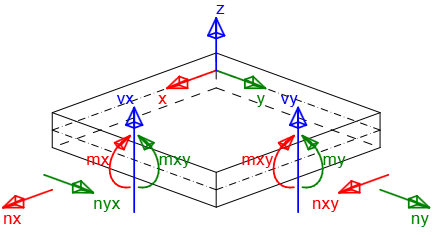
\[ \textsf{\textit{\footnotesize{Sign convention of internal forces}}}\]
De volgende typen combinaties moeten worden gedefinieerd voor normtoetsingen:
- Uiterste grenstoestand/Accidenteel – interne-krachtcomponenten gedefinieerd voor dit type combinaties worden gebruikt voor UGT-normtoetsingen van 2D-elementen:
- Capaciteit N-M-M
- Respons N-M-M
- Interactie
en de toetsing van detailleringsbepalingen
- Karakteristiek – interne-krachtcomponenten gedefinieerd voor dit type combinatie worden gebruikt voor de toetsing van spanningsbegrenzing (BGT)
- Quasi-permanent – interne-krachtcomponenten gedefinieerd voor dit type combinatie worden gebruikt voor de toetsing van scheurwijdte (BGT)
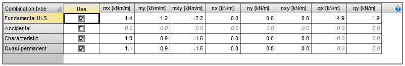
| Opmerking: |
| Interne-krachtcomponenten vx en vy hoeven niet te worden ingevoerd voor combinatietypen Karakteristiek en Quasi-permanent, omdat deze waarden niet worden gebruikt in normtoetsingen. |
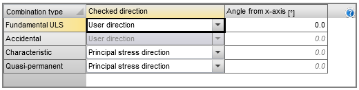
Bepaling van de toetsingsrichting
De toetsingsrichting moet worden bepaald voor de juiste normtoetsing van het 2D-element. De toetsingsrichting kan voor elk combinatietype afzonderlijk worden ingevoerd via de volgende twee methoden:
- Door gebruiker gedefinieerde richting – de gebruiker definieert de toetsingsrichting als een hoek ten opzichte van de x-as in het vlak van het 2D-element. Deze optie is standaard ingesteld voor combinatietype UGT en de vooraf ingestelde waarde van de hoek is 0 graden. Normtoetsingen worden uitgevoerd in de volgende richtingen:
- Gedefinieerde richting
- Richting loodrecht op de gedefinieerde richting
- Richting van de drukdiagonaal aan het bovenoppervlak
- Richting van de drukdiagonaal aan het onderoppervlak
- Richting van hoofdspanningen – de toetsingsrichting wordt automatisch berekend als de richting van de hoofdspanningen aan het boven- en onderoppervlak van het 2D-element. Deze optie is standaard ingesteld voor combinatietypen Karakteristiek en Quasi-permanent. Normtoetsingen worden uitgevoerd in de volgende richtingen:
- Richting van de hoofdspanningen aan het onderoppervlak
- Richting loodrecht op de richting van de hoofdspanningen aan het onderoppervlak
- Richting van de drukdiagonaal aan het onderoppervlak
- Richting van de hoofdspanningen aan het bovenoppervlak
- Richting loodrecht op de richting van de hoofdspanningen aan het bovenoppervlak
- Richting van de drukdiagonaal aan het bovenoppervlak
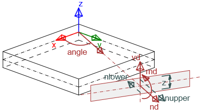
\[ \textsf{\textit{\footnotesize{Recalculated internal forces in input direction by theory of Baumann}}}\]
Analyse van de toetsingsrichting voor de uiterste grenstoestand
Analyse 1
Voor een 2D-element belast met alleen buigende momenten (mx = 20 kNm/m, my = 10 kNm/m, mxy = 5 kNm/m) waarbij de hoek van de wapening en de hoek van de toetsingsrichting zijn gewijzigd voor de uiterste grenstoestand, worden de resultaten weergegeven in de volgende grafiek:
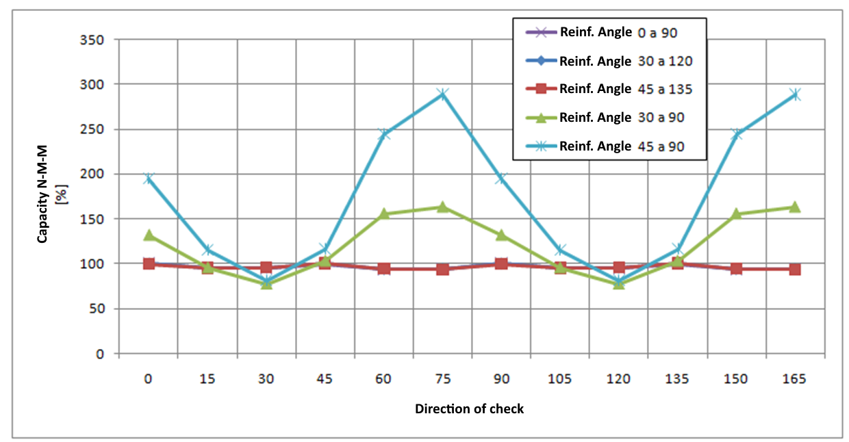
De analyse impliceert:
- Als wapeningsstaven loodrecht op elkaar staan, zijn de toetsingsresultaten vergelijkbaar voor verschillende toetsingsrichtingshoeken; ze zijn niet afhankelijk van de gedefinieerde wapeningshoek en de maximale waarde van de toetsing wordt gevonden voor hoeken van 0, 45 en 90 graden. Deze toetsing kan dus worden uitgevoerd voor een vooraf ingestelde toetsingshoek van 0 graden.
- Als wapeningsstaven niet loodrecht op elkaar staan, verschillen de toetsingsresultaten aanzienlijk en wordt de maximale toetsingswaarde bereikt bij benadering in de richting die overeenkomt met de richting van de gemiddelde wapening. Het wordt daarom aanbevolen de vooraf ingestelde toetsingsrichting te wijzigen of toetsingen in meerdere richtingen uit te voeren wanneer wapeningsstaven niet loodrecht op elkaar staan.
Analyse 2
Voor de orthogonale wapening zijn de waarden van de buigende momenten en de hoek gewijzigd voor de UGT-normtoetsing. De resultaten zijn weergegeven in de grafiek:
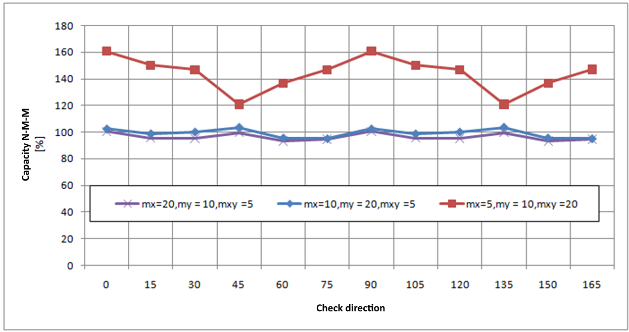
De analyse impliceert dat zelfs voor verschillende waarden van buigende momenten de maximale waarde van de uiterste-grenstoestandstoetsing wordt gevonden voor toetsingsrichtingen van 0, 45 en 90 graden. De toetsing kan dus worden uitgevoerd voor een vooraf ingestelde toetsingshoek van 0 graden. Een vergelijkbare conclusie geldt voor 2D-elementen die alleen door normaalkracht worden belast of door normaalkracht gecombineerd met buigende momenten.
Herberekening van interne krachten naar toetsingsrichtingen
De gedefinieerde interne krachten worden herberekend naar de toetsingsrichtingen met behulp van de Baumann-transformatieformule, beschreven in Baumann, Th. : "Zur Frage der Netzbewehrung von Flächentragwerken". In : Der Bauingenieur 47 (1972), Berlin 1975. De berekeningsprocedure is als volgt:
- Berekening van normaalkrachten aan beide oppervlakken van het 2D-element
- Berekening van hoofdkrachten aan beide oppervlakken van het 2D-element
- Berekening van herberekende krachten voor elk oppervlak naar de gedefinieerde toetsingsrichting
- Berekening van herberekende krachten voor elk oppervlak naar het middelpunt
- Herberekening van dwarskrachten naar de gedefinieerde toetsingsrichting
Berekening van normaalkrachten aan beide oppervlakken van het 2D-element
Gedefinieerde interne krachten worden herberekend naar beide oppervlakken met behulp van de volgende formules:
\[{{n}_{x,low\left( upp \right)}}=\frac{{{n}_{x}}}{2}+\left( - \right)\frac{{{m}_{x}}}{z}\]
\[{{n}_{y,low\left( upp \right)}}=\frac{{{n}_{y}}}{2}+\left( - \right)\frac{{{m}_{y}}}{z}\]
\[~~~~~{{n}_{xy,low\left( upp \right)}}=\frac{{{n}_{xy}}}{2}+\left( - \right)\frac{{{m}_{xy}}}{z}\]
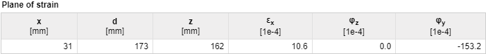
De inwendige krachtsarm (z) moet worden bepaald voor de herberekening van interne krachten. De inwendige krachtsarm wordt bepaald uit de methode van de grensrek bij belasting door het maatgevende buigend moment in de richtingen van de hoofdmomenten m1 aan beide oppervlakken. Als de hoofdmomenten gelijk zijn aan nul of als het evenwicht niet wordt gevonden in de richting van de hoofdmomenten, wordt de inwendige krachtsarm bepaald volgens de formule:
\[z=x\cdot d\]
| Omschrijving | |
| x | De coëfficiënt voor de berekening van de inwendige krachtsarm is gedefinieerd in de nationale norminstelling. |
| d | De effectieve hoogte van de doorsnede, afzonderlijk berekend voor het boven- en onderoppervlak van het 2D-element. Voor het onderoppervlak is dit de afstand van het zwaartepunt van de wapeningsstaven aan het onderoppervlak tot de bovenrand van de doorsnede. Voor het bovenoppervlak is dit de afstand van het zwaartepunt van de wapeningsstaven aan het bovenoppervlak tot de onderrand van de doorsnede. |
| Opmerking: |
| De inwendige krachtsarm kan worden geverifieerd in de Respons N-M-M normtoetsing. Alleen de buigende momenten hoeven te worden ingevoerd en de toetsingsrichting moet overeenkomen met de richting van het hoofdmoment. |
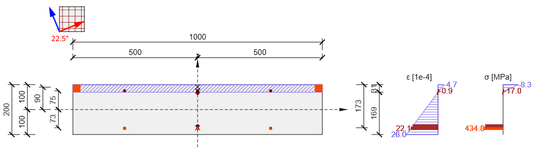
In het volgende diagram wordt een verificatie van de inwendige krachtsarm weergegeven voor buigende momenten mx = 20 kNm/m, my = 10 kNm/m, mxy = 5 kNm/m. De richting van de hoofdmomenten is berekend als αm1 = 22,5 graden en de respons van de doorsnede is berekend om de inwendige krachtsarm te bepalen.
| Opmerking: |
| Inwendige krachtsarmen voor herberekening van interne krachten in de toetsingsrichting en inwendige krachtsarmen voor normtoetsingen kunnen verschillen, omdat de inwendige krachtsarm voor herberekening wordt bepaald op een doorsnede belast door hoofdmomenten in de richting van de hoofdmomenten, en de inwendige krachtsarm voor de normtoetsing wordt bepaald op een doorsnede belast door buigende momenten en normaalkrachten in de toetsingsrichting. Waarden van inwendige krachtsarmen voor alle combinatietypen worden weergegeven in de tabel Herberekende krachten in de navigator Interne krachten in doorsnede. |
Berekening van interne krachten aan beide oppervlakken
Hoofdkrachten aan beide oppervlakken van het 2D-element worden berekend met de formule:
\[{{n}_{1,bot\left( top \right)}}=\frac{{{n}_{x,low\left( upp \right)+}}{{n}_{y,low\left( upp \right)}}}{2}+\frac{1}{2}\sqrt{{{\left( {{n}_{x,low\left( upp \right)-}}{{n}_{y,low\left( upp \right)}} \right)}^{2}}+4\cdot {{n}_{xy,low\left( upp \right)}}}\]
\[{{n}_{2,bot\left( top \right)}}=\frac{{{n}_{x,low\left( upp \right)+}}{{n}_{y,low\left( upp \right)}}}{2}-\frac{1}{2}\sqrt{{{\left( {{n}_{x,low\left( upp \right)-}}{{n}_{y,low\left( upp \right)}} \right)}^{2}}+4\cdot {{n}_{xy,low\left( upp \right)}}}\]
En de richting van de hoofdkrachten wordt berekend met de formule:
\[{{\alpha }_{n1,low\left( upp \right)}}=0,5\cdot {{\tan }^{-1}}\left( \frac{2\cdot {{n}_{xy,low\left( upp \right)}}}{{{n}_{x,low\left( upp \right)}}-{{n}_{y,low\left( upp \right)}}} \right)\]
| Opmerking: |
| Hoofdkrachten en de richting van de hoofdkrachten voor beide oppervlakken van het 2D-element worden voor alle combinatietypen weergegeven in de tabel Herberekende krachten in de navigator Interne krachten in doorsnede. |
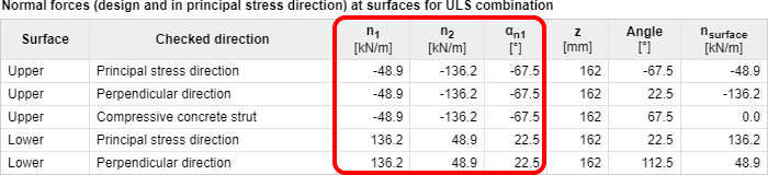
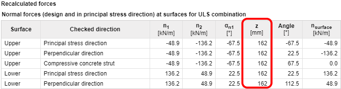
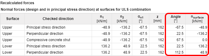
Berekening van herberekende interne krachten aan oppervlakken naar de gedefinieerde toetsingsrichting
Herberekening van hoofdkrachten naar de toetsingsrichtingen wordt afzonderlijk uitgevoerd voor elk oppervlak met behulp van de Baumann-transformatieformule:
\[{{n}_{surface,i,low\left( upp \right)}}=\frac{{{n}_{1,low\left( upp \right)}}\cdot \sin \left( {{\alpha }_{j,low\left( upp \right)}} \right)\cdot \sin \left( {{\alpha }_{k,low\left( upp \right)}} \right)+{{n}_{2,low\left( upp \right)}}\cdot \cos \left( {{\alpha }_{j,low\left( upp \right)}} \right)\cdot \cos \left( {{\alpha }_{k,low\left( upp \right)}} \right)}{\sin \left( {{\alpha }_{j,low\left( upp \right)}}-{{\alpha }_{i,low\left( upp \right)}} \right)\cdot \sin \left( {{\alpha }_{k,low\left( upp \right)}}-{{\alpha }_{i,low\left( upp \right)}} \right)}\]
| Omschrijving | |
| i, j, k, i | Index van toetsingsrichting (herberekeningsrichting van interne krachten) i, j, k, i = 1, 2, 3, 1. Bijv. voor het onderoppervlak en berekening van de kracht in de j-richting (hoek α2) is de formule: \[{{n}_{surface,2,low}}=\frac{{{n}_{1,low}}\cdot \sin {{\alpha }_{3,low}}\cdot \sin {{\alpha }_{1,low}}+{{n}_{2,low}}\cdot \cos {{\alpha }_{3,low}}\cdot \cos {{\alpha }_{1,low}}}{\sin \left( {{\alpha }_{3,low}}-{{\alpha }_{2,low}} \right)\cdot \sin \left( {{\alpha }_{1,low}}-{{\alpha }_{2,low}} \right)}\] |
| \[{{\alpha }_{i,j,k,low\left( upp \right)}}\] | De hoek tussen de gedefinieerde toetsingsrichting of de richting van de drukdiagonaal en de richting van de hoofdkrachten aan het onder- of bovenoppervlak van het 2D-element. Gedefinieerde toetsingsrichting α1, low(upp) = α1 – α low(upp) Richting loodrecht op de gedefinieerde richting α2, low(upp) = α2 – α low(upp) De toetsingsrichting voor de drukdiagonaal α3, low(upp) = α3 – α low(upp) |
| α1 | Gedefinieerde toetsingsrichting voor de betreffende combinatie |
| α2 | De richting loodrecht op de gedefinieerde richting, α2 = α1 + 90 graden |
| α3 | Toetsingsrichting in de richting van de drukdiagonaal in het vlak van het 2D-element. Deze richting wordt geoptimaliseerd om de kracht in deze richting te minimaliseren. |
| Opmerking: |
Als de toetsingsrichting identiek is aan de richting van de hoofdspanningen, zijn de krachten in de drukdiagonaal nul en wordt deze richting daarom niet meegenomen in de normtoetsing. De richting van de drukdiagonaal voor alle spanningstoestanden behalve de hyperbolische spanningstoestand (n1,low(upp) > 0 en n1,low(upp) < 0) kan worden berekend volgens de formule: α3 = 0,5(α1 + α2) Herberekende interne krachten voor beide oppervlakken van het 2D-element en alle toetsingsrichtingen inclusief de richting van de drukdiagonaal worden weergegeven in de tabel Herberekende krachten |
Transformatie van herberekende interne krachten naar het zwaartepunt van de doorsnede
Voor de normtoetsing van het 2D-element moeten de oppervlaktekrachten in een bepaalde richting worden herberekend naar het zwaartepunt van de doorsnede. Het resultaat is een normaalkracht nd,i en een buigend moment md,I werkend in het zwaartepunt van de doorsnede van het 2D-element.
md,i = nlower,i·zs,low + nupper,i·zs,upp
nd,i = nlower,i + nupper,i
| Omschrijving | |
| nlower,i | Herberekende oppervlaktekrachten aan het onderoppervlak in de ide toetsingsrichting, waarbij nlower,i = nsurface,low,i. |
| nupper,i | Herberekende interne krachten aan het bovenoppervlak in de ide toetsingsrichting, waarbij nupper,i = nsurface,upp,i. |
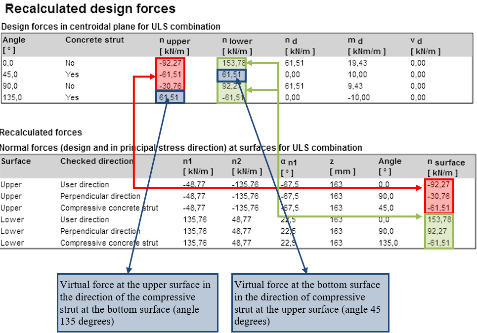
| zs,low (upp) | Afstand van het zwaartepunt van het gedrukte beton of het zwaartepunt van de wapening aan het onder- (boven-)oppervlak, waarbij z = zs,low + zs,upp |
| Opmerking: |
| Als de richtingen van de drukdiagonalen aan het onder- en bovenoppervlak verschillen, is het voor de herberekening van krachten naar het zwaartepunt noodzakelijk om virtuele krachten te berekenen aan het onderoppervlak in de richting van de drukdiagonaal aan het bovenoppervlak en vice versa. |
\[ \textsf{\textit{\footnotesize{Recalculated design forces}}}\]
Herberekening van dwarskrachten naar de gedefinieerde toetsingsrichting
Dwarskrachten worden herberekend naar de toetsingsrichting met behulp van de formule:
\[{{v}_{d,i}}={{v}_{x}}\cdot \cos ({{\alpha }_{i}})+{{v}_{y}}\cdot \sin ({{\alpha }_{i}})\]
en de maximale dwarskracht is:
\[{{v}_{d,max~}}=\sqrt{{{v}_{x}}^{2}+{{v}_{y}}^{2}}\]
en deze werkt in de richting
\[\beta ={{\tan }^{-1}}\left( \frac{{{v}_{y}}}{{{v}_{x}}} \right)\]
| Omschrijving | |
| αi | De hoek van de toetsing in de ide richting |
| Opmerking: |
| Bij de normtoetsing van een 2D-element met relatief grote dwarskrachten is het geschikt om het 2D-element te toetsen in de richting van de maximale dwarskracht, wat betekent dat de gedefinieerde toetsingsrichting overeenkomt met hoek β |
Vergelijking van herberekening van interne krachten met behulp van verschillende methoden
Herberekening van krachten volgens EN 1992-1-1
De methode beschreven in EN 1992-1-1 wordt in diverse programma's en in de praktijk gebruikt om maatgevende interne krachten te berekenen. EN 1992-1-1 houdt alleen rekening met loodrechte waperingsrichtingen. De berekening van maatgevende krachten met de invloed van het torsiemoment is beschreven in het volgende stroomschema, waarbij my³ mx. Een vergelijkbaar diagram kan worden opgesteld voor momenten my < mx
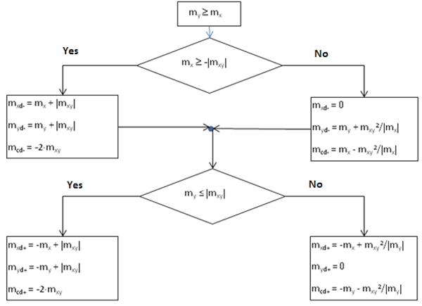
| Omschrijving | |
| mxd+, mxd- | Maatgevend buigend moment in de richting van de x-as voor het ontwerp en de normtoetsing van de wapening aan het onder- (-) of bovenoppervlak (+) |
myd+ myd- | Maatgevend buigend moment in de richting van de y-as voor het ontwerp en de normtoetsing van de wapening aan het onder- (-) of bovenoppervlak (+) |
| mcd+, mcd- | Maatgevend buigend moment in de gedrukte betonnen drukdiagonaal aan het onder- (-) of bovenoppervlak (+), dat door het beton moet worden opgenomen |
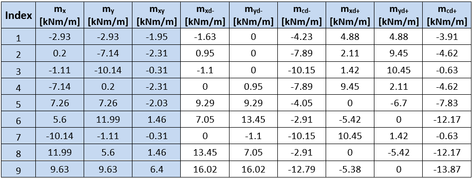
Waarden van herberekende maatgevende krachten voor het type staaf = Plaat, berekend met de methode beschreven in de EN, worden weergegeven in de volgende tabel:
In IDEA StatiCa RCS worden waarden van momenten aan het boven- en onderoppervlak niet weergegeven, maar waarden van normaalkrachten aan beide oppervlakken en waarden van momenten herberekend naar het zwaartepunt van de doorsnede.
Momenten aan het onder- en bovenoppervlak kunnen worden berekend met behulp van oppervlaktekrachten, die worden weergegeven in de numerieke uitvoer, met de formule:
\[{{m}_{surface,i,dlow\left( upp \right)}}={{n}_{surface,i,low\left( upp \right)}}\cdot z\]
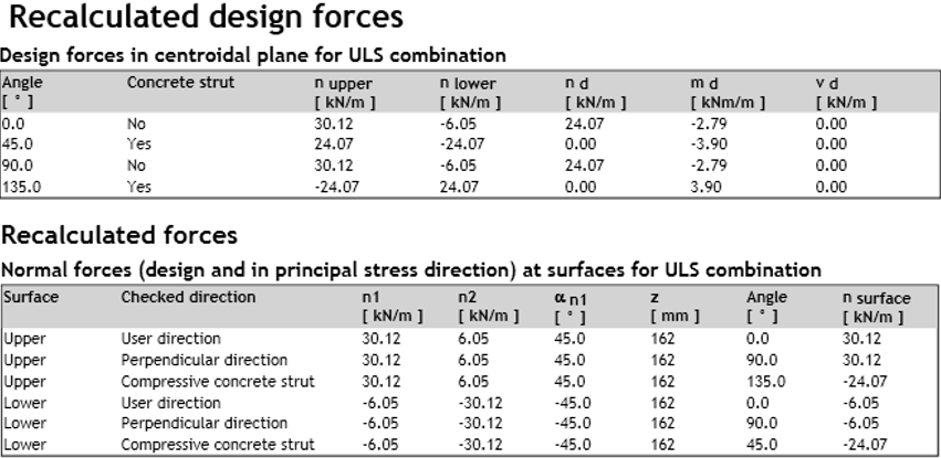
Waarden van oppervlaktekrachten en herberekende momenten worden weergegeven in de volgende tabellen:
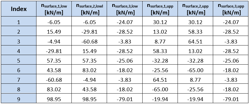
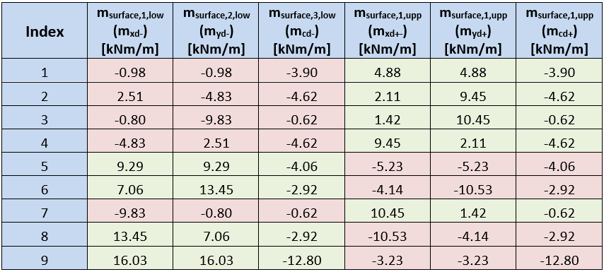
De tabellen tonen dat momenten aan plaatoppervlakken berekend in IDEA Concrete en berekend volgens de methode beschreven in de EN, alleen aan één oppervlak overeenkomen. Dit verschil wordt veroorzaakt door een verschillende optimalisatie van de betonnen drukdiagonaal. De methode gebruikt in IDEA StatiCa RCS zoekt naar de hoek van de drukdiagonaal bij de minimale kracht in de diagonaal. De methode beschreven in de EN zoekt naar een minimale som van negatieve krachten uit alle richtingen.
Vergelijking van berekening van interne krachten met programma's RFEM en SCIA Engineer
Om de resultaten van herberekende interne krachten in de programma's IDEA Concrete, RFEM en SCIA Engineer (SEN) te vergelijken, werd een eenvoudig model van een plaat met afmetingen 6 m x 4 m en dikte 200 mm opgesteld. De plaat is ondersteund met lijnondersteuning aan de randen en belast met een gelijkmatig verdeelde belasting van 10 kN/m2.
Ter vereenvoudiging van de presentatie worden alleen waarden van herberekende interne krachten in één langsdoorsnede weergegeven. De afstand van de doorsnede tot de plaatrand bedraagt 1,5 m. De interne krachten berekend in het programma RFEM werden gebruikt als invoerwaarden voor IDEA Concrete.
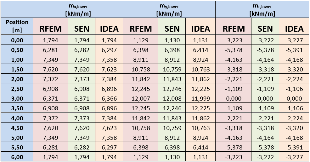
De tabel toont een goede overeenstemming van krachten berekend in de afzonderlijke programma's.