De weerstand van ankerbout wordt beoordeeld volgens STO 36554501-048-2016 voor kopdeuvel en achteraf aangebrachte ankers. STO maakt vaak gebruik van tabelwaarden in de bijlage; in dat geval worden de formules uit SP 43, SP16 of EN 1992-4 gebruikt vanwege hun algemene geldigheid. Uitrekfalen van rechte ankers, gecombineerd uitrek- en bezwijken van het beton van gelijmde ankers, en splijtfalen van beton worden niet getoetst vanwege ontbrekende informatie die alleen beschikbaar is voor het specifieke anker- en lijmtype van de ankerfabrikant.
In de norminstellingen kan beton worden ingesteld als gescheurd of ongescheurd. De weerstanden van ongescheurd beton zijn hoger.
Trek staalweerstand (SP 43 - Bijlage G):
De trek staalweerstand van ankers in STO maakt gebruik van tabelwaarden in Bijlage A. Daarom wordt een algemene formule uit SP 43 - Bijlage G gebruikt.
\[ N_{ult,s} = \frac{A_{sa} \cdot R_{ba} \cdot \gamma_c}{k_0} \]
waarbij:
- Rba = 0.8 ⋅ Rbyn – rekenwaarde vloeisterkte van de ankerbout
- Rbyn – karakteristieke vloeisterkte van het ankerstaal
- Asa – netto dwarsdoorsnede-oppervlak van een bout
- k0 – factor voor belastingtype; bewerkbaar in norminstellingen; k0 = 1.05 voor statische belasting en k0 = 1.35 voor dynamische belasting; voor draagbare ankers met ankerplaten, vrij geplaatst in de buizen, wordt k0 gelijk gesteld aan 1.15 voor dynamische belastingen (SP 43 – G.9)
- γc – gebruiksfactor – SP 16, Tabel 1, bewerkbaar in norminstellingen
Uitrekweerstand (EN 1992-4, Art. 7.2.1.5)
De uitrekweerstand van ankers in STO maakt gebruik van tabelwaarden in Bijlage A. Daarom wordt de algemene formule uit EN 1992-4, Art. 7.2.1.5 gebruikt voor ankers met ankerplaten:
\[ N_{ult,p}=\frac{N_{n,p} \cdot \psi_c}{\gamma_{bt} \gamma_{Np}} \]
waarbij:
- Nn,p \(\cdot \psi_c\) = k2 ∙ Ah ∙ Rbn – karakteristieke weerstand bij uitrekfalen
- k2 – coëfficiënt afhankelijk van betontoestand, k2 = 7.5 voor gescheurd beton, k2 = 10.5 voor ongescheurd beton
- Ah – draagoppervlak van de ankerkop; voor een ronde ankerplaat \(A_h = \frac{\pi}{4} \left ( d_h^2 - d^2 \right )\), voor een rechthoekige ankerplaat \(A_h = a_{wp}^2 - \frac{\pi}{4} d^2\)
- dh ≤ 6 th + d – diameter van de kop van het bevestigingsmiddel
- th – dikte van de kop van het bevestigingsmiddel met kop
- d – diameter van de schacht van het bevestigingsmiddel
- Rbn – karakteristieke cilinderdruksterkte van beton
- γbt – partiële veiligheidsfactor voor beton (bewerkbaar in norminstellingen)
- γNp – partiële veiligheidsfactor die rekening houdt met de installatieveiligheid van een ankersysteem (bewerkbaar in norminstellingen)
De uitrekweerstand van andere ankertypen wordt niet getoetst en moet worden gegarandeerd door de fabrikant of worden bepaald via STO, Bijlage A.
Weerstand tegen betonkegelfalen van een anker of ankergroep (STO - Art. 6.1.3):
\[N_{ult,c}=\frac{N_{n,c}^0}{\gamma_{bt} \cdot \gamma_{Nc}} \cdot \frac{A_{c,N}}{A_{c,N}^0} \cdot \psi_{s,N} \cdot \psi_{re,N} \cdot \psi_{ec,N}\]
waarbij:
- \(N_{n,c}^0 = k_1 \sqrt{R_{b,n}} h_{ef}^{1.5}\) – karakteristieke weerstand van een enkel bevestigingsmiddel geplaatst in beton, niet beïnvloed door aangrenzende bevestigingsmiddelen of randen van het betonelement
- k1 – factor die rekening houdt met de betontoestand; k1 = 8.4 voor gescheurd beton en k1 = 11.8 voor ongescheurd beton
- Rb,n – karakteristieke cilinderdruksterkte van beton
- hef – inbeddiepte van het anker in beton; bij drie of vier nabijgelegen randen wordt de effectieve \(h'_{ef} = \max \left \{ \frac{c_{max}}{c_{cr,N}} \cdot h_{ef}, \, \frac{s_{max}}{s_{cr,N}} \cdot h_{ef} \right \}\) gebruikt in de formules voor Nn,c0, ccr,N, scr,N, Ac,N, Ac,N0, ψs,N, en ψec,N
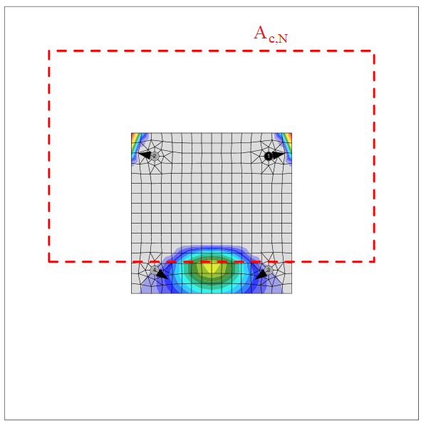
- Ac,N – werkelijk geprojecteerd oppervlak, begrensd door overlappende betonkegels van aangrenzende bevestigingsmiddelen en door randen van het betonelement
- Ac,N0 = scr,N2 – referentie geprojecteerd oppervlak, d.w.z. het betonoppervlak van een individueel anker met grote onderlinge afstand en randafstand aan het betonoppervlak
- \(\psi_{s,N}=0.7+0.3 \cdot \frac{c}{c_{cr,N}} \le 1\) – factor die rekening houdt met verstoring van de spanningsverdeling in het beton door de nabijheid van een rand van het betonelement
- c – kleinste randafstand
- ccr,N = 1.5 ∙ hef – karakteristieke randafstand voor het waarborgen van de overdracht van de karakteristieke weerstand van een anker bij betonuitbraak onder trekbelasting
- \(\psi_{re,N}=0.5+\frac{h_{ef}}{200} \le 1\) – schaalfactor voor afschilfering
- \(\psi_{ec,N}=\frac{1}{1+2 \cdot (e_N / s_{cr,N})} \le 1\) – factor die rekening houdt met het groepseffect wanneer verschillende trekkrachten werken op de afzonderlijke bevestigingsmiddelen van een groep; ψec,N wordt afzonderlijk bepaald voor elke richting en het product van beide factoren wordt gebruikt
- eN – excentriciteit van de resulterende trekkracht van de getrokken bevestigingsmiddelen ten opzichte van het zwaartepunt van de getrokken bevestigingsmiddelen
- scr,N = 2 ∙ ccr,N – karakteristieke hartafstand van ankers om de karakteristieke weerstand van de ankers te waarborgen bij betonkegelfalen onder trekbelasting
- γbt – partiële veiligheidsfactor voor beton (bewerkbaar in norminstellingen)
- γNc – partiële veiligheidsfactor die rekening houdt met de installatieveiligheid van een ankersysteem (bewerkbaar in norminstellingen)
Het betonuitbraakkegel-oppervlak voor een groep ankers belast door trek die een gemeenschappelijke betonkegel vormen, Ac,N, is weergegeven met een rode stippellijn.
Afschuiving staalweerstand van anker (SP16 - Art. 14.2.9 en STO - Art. 6.2.1)
Volgens STO - Art. 6.2.1 worden twee scenario's onderzocht:
- Afschuiving zonder hefboomarm (Stand-off: Direct)
- Afschuiving met hefboomarm (Stand-off: Mortelvoeg)
Afschuiving zonder hefboomarm
De afschuiving staalweerstand van ankers in STO maakt gebruik van tabelwaarden in Bijlage A. Daarom wordt een algemene formule uit SP16 gebruikt. Er wordt aangenomen dat ankers draadeinden zijn. Wrijving wordt niet in rekening gebracht.
Een bout onderworpen aan een rekenwaarde afschuifkracht wordt ontworpen volgens SP16 - Art. 14.2.9 en dient te voldoen aan:
\[ V_{ult,s} = R_{bs} A_b \gamma_b \gamma_c \]
waarbij:
- Rbs – rekenwaarde afschuifsterkte van een bout – SP 16, Tabel 5
- Ab – bruto dwarsdoorsnede-oppervlak van de bout
- γb – gebruiksfactor van boutverbinding – SP 16, Tabel 41 – γb = 1.0 voor enkelvoudige bouting en meervoudige bouting met nauwkeurigheidsklasse A, γb = 0.9 voor meervoudige bouting en nauwkeurigheidsklasse B en hoogsterkte bouten (Rbun ≥ 800 MPa)
- γc – gebruiksfactor – SP 16, Tabel 1, bewerkbaar in norminstellingen
| Rbyn [MPa] | Rbs [MPa] |
| \(R_{byn} \le 300 \) | \(0.42 \cdot R_{bun} \) |
| \(300 < R_{byn} \le 400 \) | \(0.41 \cdot R_{bun} \) |
| \(400 < R_{byn} \le 936 \) | \(0.40 \cdot R_{bun} \) |
| \(936 > R_{byn} \) | \(0.35 \cdot R_{bun} \) |
Afschuiving met hefboomarm (STO - Art. 6.2.1.5)
\[ V_{ult,s} = \frac{M_{n,s}}{l_s} \gamma_b \gamma_c \]
waarbij:
- \(M_{n,s} = M_{n,s}^0 \left ( 1- \frac{N_{an}}{N_{ult,s}} \right ) \) – karakteristieke buigweerstand van het anker verminderd door de trekkracht in het anker
- Mn,s0 = 1.2 Wel Rbun – karakteristieke buigweerstand van het anker (ETAG 001, Bijlage C – Vergelijking (5.5b))
- \( W_{el} = \frac{\pi d^3}{32}\) – weerstandsmoment van het anker
- d – diameter van de ankerbout; indien het afschuifvlak in de schroefdraad is geselecteerd, wordt de door schroefdraad gereduceerde diameter gebruikt; anders wordt de nominale diameter, dnom, gebruikt
- Rbun – treksterkte van het anker
- Nan – trekkracht in het anker
- Nult,s – trekweerstand van het anker
- ls = (0.5 dnom + tmortar + 0.5 tbp) / \(\alpha_M \) – hefboomarm
- αM = 2 – volledige inklemming wordt aangenomen
- tmortar – dikte van mortel (grout)
- tbp – dikte van de voetplaat
- γb – gebruiksfactor van boutverbinding – SP 16, Tabel 41 – γb = 1.0 voor enkelvoudige bouting en meervoudige bouting met nauwkeurigheidsklasse A, γb = 0.9 voor meervoudige bouting en nauwkeurigheidsklasse B en hoogsterkte bouten (Rbun ≥ 800 MPa)
- γc – gebruiksfactor – SP 16, Tabel 1, bewerkbaar in norminstellingen
Betonwrikfalen (STO - Art. 6.2.2):
\[ V_{ult,cp}= k \cdot \frac{N_{ult,c}}{\gamma_{V,cp}} \]
waarbij:
- k – factor voor betonwrikfalen (STO 36554501-048-2016 - Art. 6.2.2.3) standaard genomen als k = 2 (ETAG 001, Bijlage C – Art. 5.2.3.3) bewerkbaar in norminstellingen
- Nult,c – weerstand van een bevestigingsmiddel of een groep bevestigingsmiddelen bij betonkegelfalen; alle ankers worden verondersteld op trek te zijn en γNc = 1.0
- γV,cp – partiële veiligheidsfactor die rekening houdt met de installatieveiligheid van een ankersysteem bij betonwrikfalen, bewerkbaar in norminstellingen
Betonrandfalen (STO - Art. 6.2.3):
Betonrandfalen is een bros falen en het meest ongunstige geval wordt getoetst, d.w.z. alleen de ankers nabij de rand dragen de volledige afschuifbelasting die op de gehele voetplaat werkt. Als ankers in een rechthoekig patroon zijn geplaatst, draagt de rij ankers aan de onderzochte rand de afschuifbelasting. Als ankers onregelmatig zijn geplaatst, dragen de twee ankers het dichtst bij de onderzochte rand de afschuifbelasting. Twee randen in de richting van de afschuifbelasting worden onderzocht en het meest ongunstige geval wordt in de resultaten getoond.

Onderzochte randen afhankelijk van de richting van de resulterende afschuifkracht
Weerstand van een bevestigingsmiddel of een groep bevestigingsmiddelen belast in de richting van de rand:
\[ V_{ult,c}= \frac{V_{n,c}^0}{\gamma_{bt} \cdot \gamma_{Vc}} \cdot \frac{A_{c,V}}{A_{c,V}^0} \cdot \psi_{s,V} \cdot \psi_{h,V} \cdot \psi_{\alpha,V} \cdot \psi_{ec,V} \cdot \psi_{re,V} \]
waarbij:
- \( V_{n,c}^0 = k_3 \cdot d_{nom}^\alpha \cdot l_f^\beta \cdot \sqrt{R_{b,n}} \cdot c_1^{1.5}\) – beginwaarde van de karakteristieke weerstand van een bevestigingsmiddel loodrecht op de rand belast
- k3 – factor die rekening houdt met de betontoestand; k3 = 2.0 voor gescheurd beton, k3 = 2.8 voor ongescheurd beton
- \( \alpha = 0.1 \left ( \frac{l_f}{c_1} \right ) ^{0.5} \)
- \( \beta = 0.1 \left ( \frac{d_{nom}}{c_1} \right ) ^{0.2} \)
- lf = min (hef, 12 dnom) voor dnom ≤ 24 mm; lf = min [hef, max (8 dnom, 300 mm)] voor dnom > 24 mm – effectieve lengte van het anker bij afschuiving - overgenomen uit EN 1992-4 - Art. 7.2.2.5
- hef – inbeddiepte van het anker in beton
- c1 – afstand van het anker tot de onderzochte rand; voor bevestigingen in een smal, dun element wordt de effectieve afstand \( c'_1=\max \left \{ \frac{c_{2,max}}{1.5}, \, \frac{h}{1.5}, \, \frac{s_{2,max}}{3} \right \} \) gebruikt
- c2 – kleinste afstand tot de betonrand loodrecht op de afstand c1
- dnom – nominale ankerdiameter
- Ac,V0 = 4.5 c12 – oppervlak van de betonkegel van een individueel anker aan het zijdelingse betonoppervlak niet beïnvloed door randen
- Ac,V – werkelijk oppervlak van de betonkegel van de verankering aan het zijdelingse betonoppervlak
- \(\psi_{s,V} = 0.7+0.3 \frac{c_2}{1.5 c_1} \le 1.0 \) – factor die rekening houdt met de verstoring van de spanningsverdeling in het beton door verdere randen van het betonelement op de afschuifweerstand
- \( \psi_{h,V} = \left ( \frac{1.5 c_1}{h} \right ) ^ {0.5} \ge 1.0 \) – factor die rekening houdt met het feit dat de afschuifweerstand niet evenredig afneemt met de elementdikte zoals aangenomen door de verhouding Ac,V / Ac,V0
- \( \psi_{\alpha,V} = \sqrt{\frac{1}{(\cos \alpha_V)^2 + (0.4 \sin \alpha_V)^2}} \ge 1 \) – houdt rekening met de hoek αV tussen de aangebrachte belasting, V, en de richting loodrecht op de vrije rand van het betonelement
- \( \psi_{ec,V} = \frac{1}{1+e_V / (1.5 c_1)} \le 1 \) – factor die rekening houdt met een groepseffect wanneer verschillende afschuifkrachten werken op de afzonderlijke ankers van een groep
- ψre,V = 1.0 – factor die rekening houdt met het effect van het type wapening gebruikt in gescheurd beton
- h – hoogte van het betonblok
- γbt – partiële veiligheidsfactor voor beton (bewerkbaar in norminstellingen)
- γVc – partiële veiligheidsfactor die rekening houdt met de installatieveiligheid van een ankersysteem (bewerkbaar in norminstellingen)
Interactie van trek- en afschuifkrachten (STO - Art. 6.3):
De interactie van trek- en afschuifkrachten wordt bepaald volgens STO - Art. 6.3., Vergelijking (6.55):
\[ \beta_N^{1.5} + \beta_V^{1.5} \le 1.0 \]
waarbij:
- \(\beta_N = \max \left \{ \frac{N_{an}}{N_{ult,s}}; \, \frac{N_{an}}{N_{ult,p}}; \, \frac{N_{an}}{N_{ult,c}} \right \} \) – coëfficiënt gedefinieerd als de grootste waarde van de verhouding van de rekenwaarde trekkrachten tot de waarde van de uiterste trekweerstanden voor elk van de faalmechanismen
- \(\beta_V = \max \left \{ \frac{V_{an}}{V_{ult,s}}; \, \frac{V_{an}}{V_{ult,cp}}; \, \frac{V_{an}}{V_{ult,c}} \right \} \) – coëfficiënt gedefinieerd als de grootste waarde van de verhouding van de rekenwaarde afschuifkrachten tot de waarde van de uiterste afschuifweerstanden voor elk van de faalmechanismen
Ankers met stand-off
Een anker met stand-off wordt ontworpen als een staafelement belast door afschuifkracht, buigend moment en druk- of trekkracht. Deze inwendige krachten worden bepaald door een eindige elementen model. Het anker is aan beide zijden ingeklemd, één zijde bevindt zich 0.5×d onder het betonniveau, de andere zijde bevindt zich in het midden van de dikte van de plaat. De kniklengte wordt conservatief aangenomen als tweemaal de lengte van het staaflement. Het plastisch weerstandsmoment wordt gebruikt. Het staaflement wordt ontworpen volgens SP 16. De afschuifkracht kan de vloeisterkte van het staal verminderen, maar de minimale lengte van het anker om de moer onder de voetplaat te plaatsen zorgt ervoor dat het anker bezwijkt door buiging voordat de afschuifkracht de helft van de afschuifweerstand bereikt. De reductie is daarom niet noodzakelijk. De interactie van buigend moment en druk- of treksterkte wordt lineair aangenomen.
Afschuifweerstand:
Een bout onderworpen aan een rekenwaarde afschuifkracht wordt ontworpen volgens SP16 - Art. 14.2.9 en dient te voldoen aan:
\[ V_{ult,s} = R_{bs} A_{bn} \gamma_b \gamma_c \]
waarbij:
- Rbs – rekenwaarde afschuifsterkte van een bout – SP 16, Tabel 5
- Abn – bruto dwarsdoorsnede-oppervlak van de bout
- γb – gebruiksfactor van boutverbinding – SP 16, Tabel 41 – γb = 1.0 voor enkelvoudige bouting en meervoudige bouting met nauwkeurigheidsklasse A, γb = 0.9 voor meervoudige bouting en nauwkeurigheidsklasse B en hoogsterkte bouten (Rbun ≥ 800 MPa)
- γc – gebruiksfactor – SP 16, Tabel 1, bewerkbaar in norminstellingen
| Rbyn [MPa] | Rbs [MPa] |
| \(R_{byn} < 300 \) | \(0.42 \cdot R_{bun} \) |
| \(300 \le R_{byn} < 400 \) | \(0.41 \cdot R_{bun} \) |
| \(400 \le R_{byn} < 936 \) | \(0.40 \cdot R_{bun} \) |
| \(936 < R_{byn} \) | \(0.35 \cdot R_{bun} \) |
Trek- en drukweerstand:
De staalweerstand van ankers in STO maakt gebruik van tabelwaarden in Bijlage A. Daarom wordt een algemene formule uit SP 43 - Bijlage G gebruikt.
\[ N_{ult,s} = \frac{A_{sa} \cdot R_{ba} \cdot \gamma_c }{k_0} \]
waarbij:
- Rba = 0.8 ⋅ Rbyn – rekenwaarde vloeisterkte van de ankerbout
- Rbyn – karakteristieke vloeisterkte van het ankerstaal
- Asa – netto dwarsdoorsnede-oppervlak van een bout
- γc – gebruiksfactor – SP 16, Tabel 1, bewerkbaar in norminstellingen
- k0 – factor voor belastingtype; bewerkbaar in norminstellingen; k0 = 1.05 voor statische belasting en k0 = 1.35 voor dynamische belasting; voor draagbare ankers met ankerplaten, vrij geplaatst in de buizen, wordt k0 gelijk gesteld aan 1.15 voor dynamische belastingen (SP 43 – G.9)
Buigweerstand:
\[ M_{ult,s} = W_n R_{ba} \gamma_c \]
- \( W_{n}= \frac{d_s^3}{6} \) – weerstandsmoment van de bout
- \(d_s = \sqrt{\frac{4A_{bn}}{\pi}}\) – ankerboutdiameter gereduceerd door schroefdraad
- Rba = 0.8 ⋅ Rbyn – rekenwaarde vloeisterkte van de ankerbout
- Rbyn – karakteristieke vloeisterkte van het ankerstaal
- γc – gebruiksfactor – SP 16, Tabel 1, bewerkbaar in norminstellingen
Benuttingsgraad staal van stand-off anker
Lineaire interactie wordt gebruikt:
\[ \frac{N}{N_{ult,s}} + \frac{M}{M_{ult,s}} \le 1 \]
Benuttingsgraad beton van stand-off anker
Alle betontoetsen worden ook uitgevoerd en de volgende interactie voor betonfalenmechanismen wordt gegeven:
\[ \beta_N^{1.5} + \beta_V^{1.5} \le 1.0 \]
waarbij:
- \(\beta_N = \max \left \{ \frac{N_{an}}{N_{ult,p}}; \, \frac{N_{an}}{N_{ult,c}} \right \} \) – coëfficiënt gedefinieerd als de grootste waarde van de verhouding van de rekenwaarde trekkrachten tot de waarde van de uiterste trekweerstanden voor elk van de faalmechanismen
- \(\beta_V = \max \left \{ \frac{V_{an}}{V_{ult,cp}}; \, \frac{V_{an}}{V_{ult,c}} \right \} \) – coëfficiënt gedefinieerd als de grootste waarde van de verhouding van de rekenwaarde afschuifkrachten tot de waarde van de uiterste afschuifweerstanden voor elk van de faalmechanismen