Brugpijler (EN)
1 Nieuw project
Open IDEA StatiCa en selecteer de Member applicatie.

Maak een nieuw project (1) aan, typ de naam en selecteer een map waar het wordt opgeslagen. Kies vervolgens het projecttype Beton (2) en wijzig de Betonkwaliteit en de Ontwerplevensduur (3). Kies het type topologie (4). Definieer de hoogte van de kolom op 22 m (5). Klik op de pijl (6) om de doorsnede in te stellen. Selecteer het tabblad Geavanceerd (7) en vervolgens I-vorm met console (8). Wijzig de afmetingen (9) en klik op de OK-knop (10). Klik ten slotte op Project aanmaken (11).

2 Ontwerp
De kolom is nu aangemaakt met bijbehorende staven. Verwijder alle Gerelateerde staven.

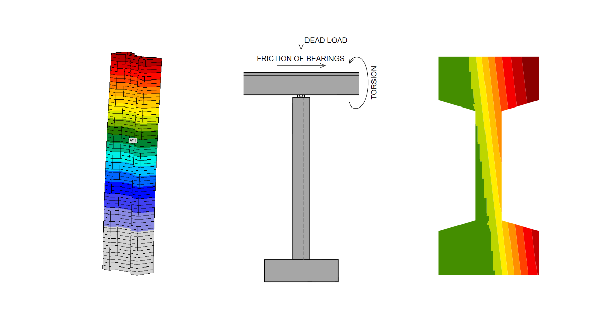
De opleggingen moeten worden aangepast. Selecteer hiervoor JOINT1 en pas de oplegging aan. Selecteer daarna het tweede JOINT2 en wijzig ook die oplegging. De vrijheidsgraden zijn gedefinieerd in de onderstaande figuur.

De volgende stap is het definiëren van de wapeningstekening. Selecteer het geanalyseerde staaf AM1 (1) en klik op de knop Wapeningsmontage (2). Selecteer vervolgens Langswapening (3) -> Nieuw op alle zijden (4).

Stel de diameter, maximale hartafstand en betondekking in.

Het laatste te definiëren onderdeel is de Belasting. Stel de belastingscombinatie in. Klik op de plus-knop om een nieuwe puntlast toe te voegen.

3 Toetsing
Het model is gereed. Ga vóór het berekenen naar Instellingen, naar Hoofdstuk 3, en stel αcc in op 0,85.

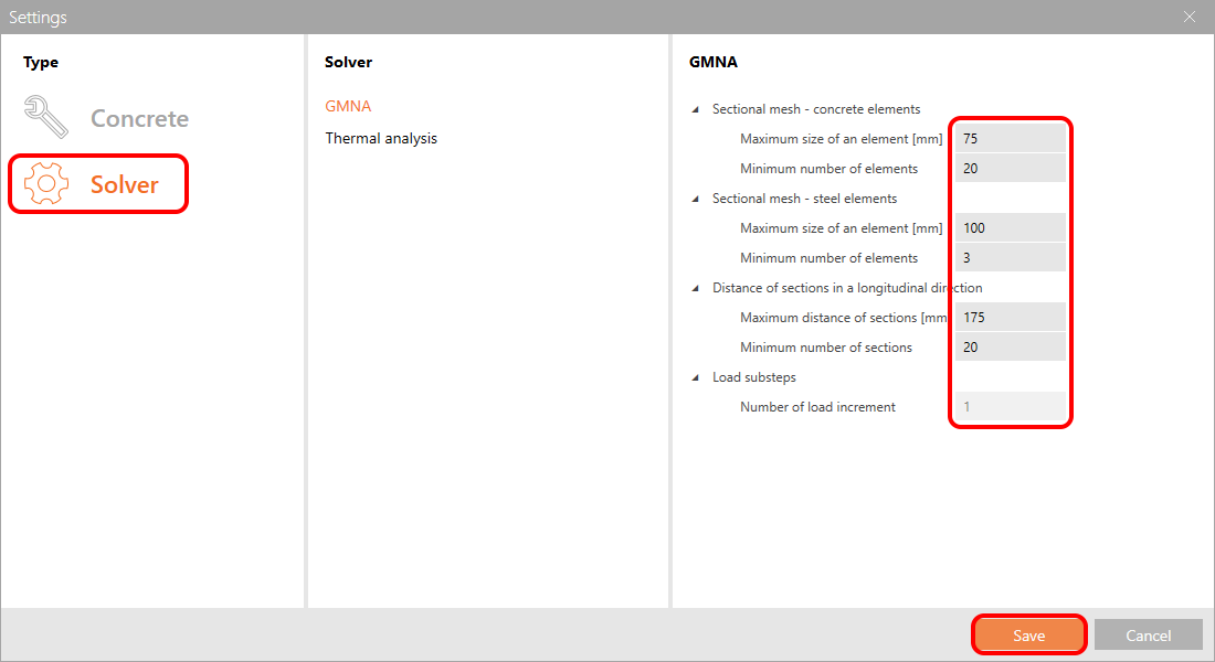
De Solver-instellingen moeten worden aangepast vanwege de omvang van het model.
Vervolgens kunt u het programma de Lineaire analyse laten uitvoeren. U ontvangt de inwendige krachten, verplaatsingen en reacties, of u kunt via de knop Gedetailleerd naar de RCS applicatie gaan om de normtoetsingen uit te voeren.
De GMNIA houdt geen rekening met afschuiving en torsie. De afschuivingstoetsing moet worden uitgevoerd met behulp van de lineaire analyse en de RCS applicatie.
We slaan de Lineaire analyse over. Meer informatie vindt u in deze tutorial: Slanke betonnen kolom (EN).
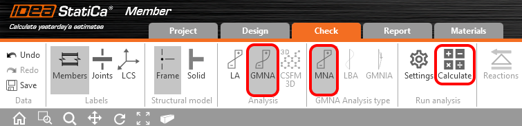
Selecteer het analysetype GMNA en ga verder naar MNA - Materieel niet-lineaire analyse.
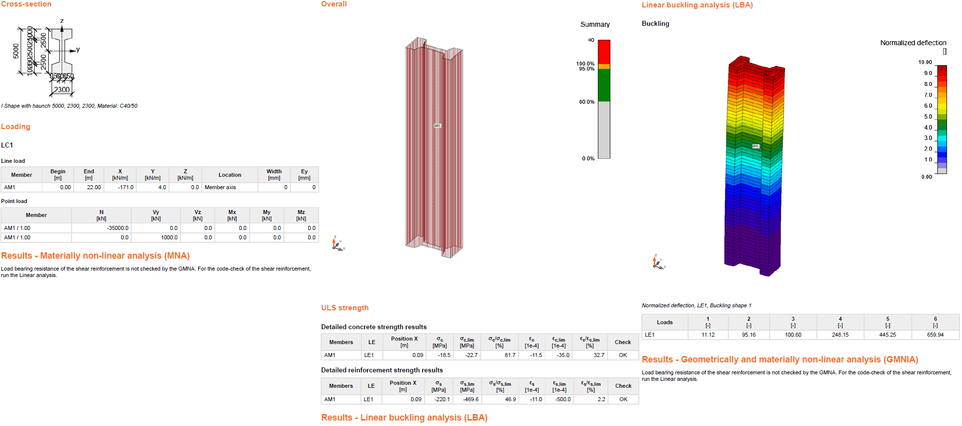
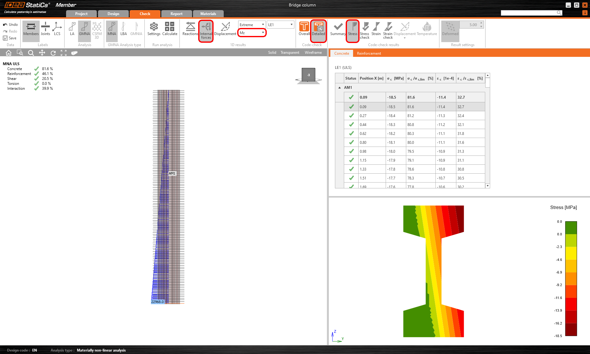
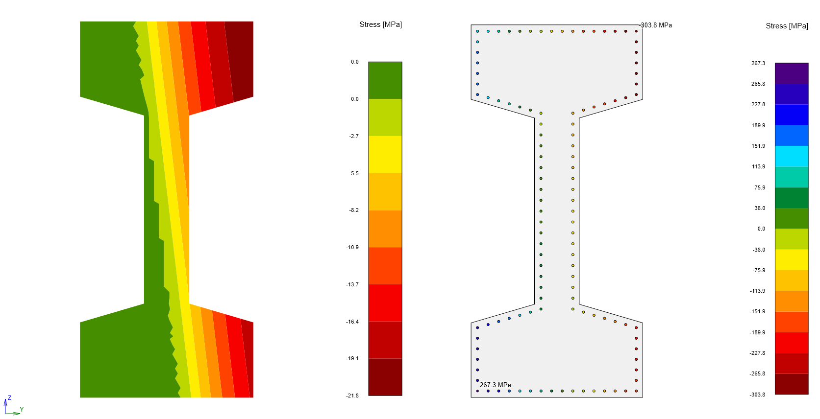
Zodra de berekening is voltooid, kunt u de resultaten controleren. Laat het programma eerst het buigend moment Mz-diagram weergeven. Vervolgens kunt u op Gedetailleerd en Spanning klikken. Vergeet niet de maatgevende doorsnede te selecteren. U ziet de spanning in het beton.
Voer de LBA - Lineaire knkanalyse uit.

Wanneer de berekening is voltooid, stelt u de Imperfectie-amplitude in. De waarde van de amplitude wordt berekend volgens EN 1992-1-1 artikel 5.2 (9).
Lees het gekoppelde artikel om te leren hoe u kruip kunt meenemen.
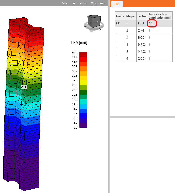
Controleer altijd het + en het - teken van de imperfectie!
Start GMNIA - Geometrisch en materieel niet-lineaire analyse met imperfecties.

Dit was het laatste analysetype. U kunt de resultaten controleren zoals bij de MNA. Door het tweede-orde-effect zijn de buigende momenten toegenomen.
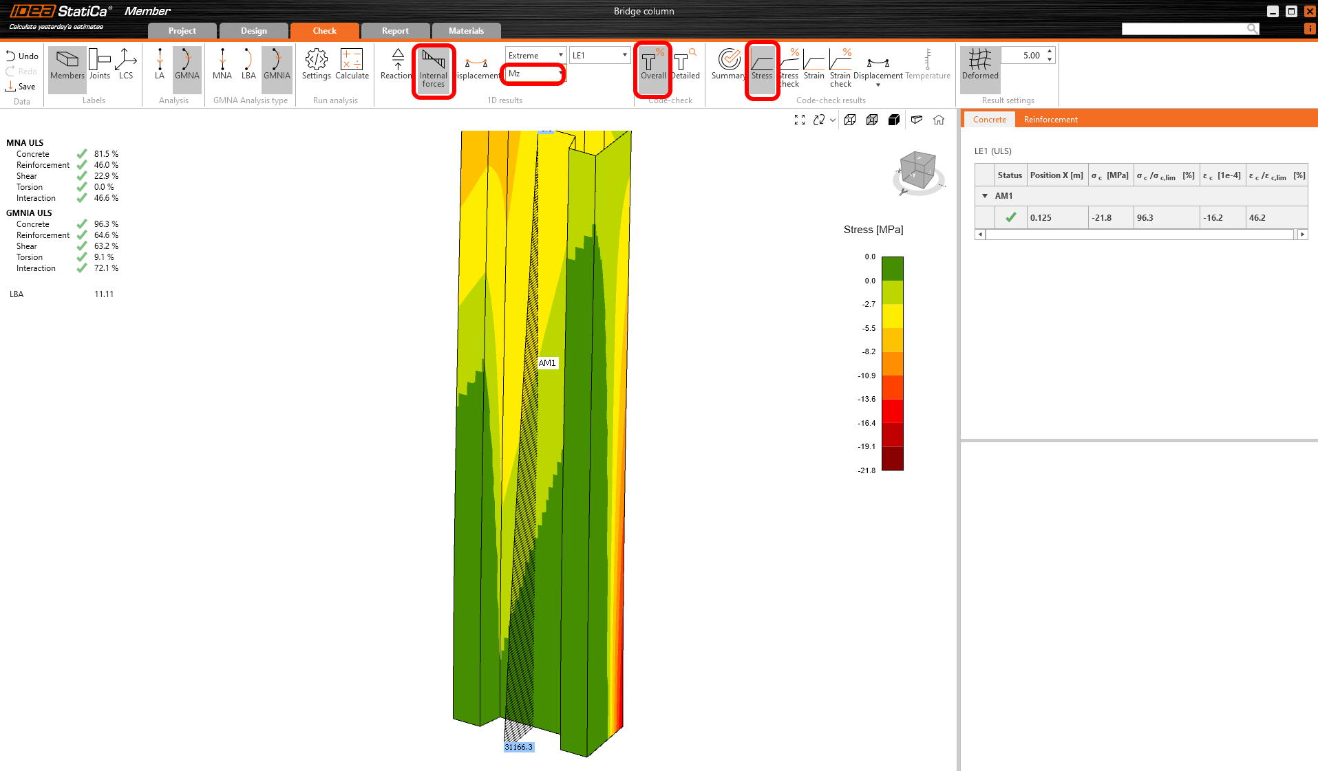
U kunt ook de spanningen in het beton en in de wapening controleren. Vergeet ook hier niet de maatgevende doorsnede te selecteren.
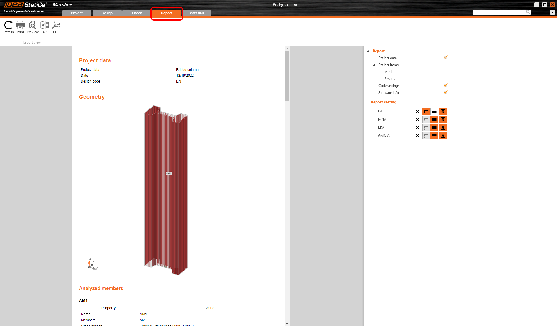
3 Rapport
Ga naar het tabblad Rapport. Hier kan het rapport worden afgedrukt.