
Rigidezza flessionale del collegamento saldato di sezioni aperte
Descrizione
La previsione della rigidezza rotazionale è descritta su un giunto a momento saldato di gronda. Viene studiato un collegamento saldato di sezione aperta con colonna HEB e trave IPE, e il comportamento del giunto è descritto su un diagramma momento-rotazione. I risultati del modello analitico con il metodo delle componenti (CM) sono confrontati con i risultati numerici ottenuti con il metodo degli elementi finiti basato sulle componenti (CBFEM). È disponibile un caso di riferimento.
Modello analitico
La rigidezza rotazionale di un giunto deve essere determinata dalla deformazione delle sue componenti di base, rappresentate dal coefficiente di rigidezza ki. La rigidezza rotazionale del giunto Sj si ottiene da:
\[ S_j = \frac{E z^2}{\mu \Sigma_i \frac{1}{k_i}} \]
dove:
- ki è il coefficiente di rigidezza per la componente del giunto i;
- z è il braccio della leva; vedere 6.2.7;
- μ è il rapporto di rigidezza; vedere 6.3.1.
Le componenti del giunto considerate in questo esempio sono: pannello d'anima della colonna a taglio k1, anima della colonna a compressione k2, e anima della colonna a trazione k3. I coefficienti di rigidezza sono definiti nella Tabella 6.11 della EN 1993-1-8:2005. La rigidezza iniziale Sj,ini si ottiene per un momento Mj,Ed ≤ 2/3 Mj,Rd.
\[S_j = \frac{E \, z^{2}}{\frac{1}{k_1} + \frac{1}{k_2} + \frac{1}{k_3}}\]
\[S_{j,\text{ini}} = \frac{S_j}{1.5^{\psi}}\]
dove
\(S_{j}\) — rigidezza rotazionale del giunto
\(\psi\) = 2.7 — EN 1993-1-8 tabella 6.8
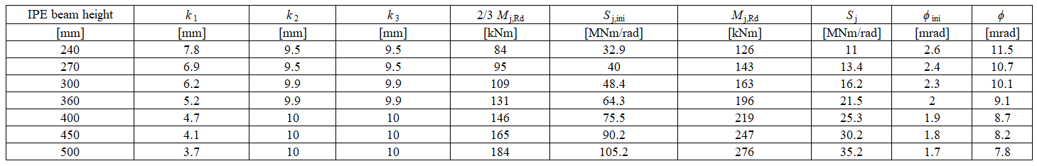
Nell'esempio, una trave a sezione aperta IPE 400 è saldata a una colonna HEB 300. Le ali della trave sono collegate alla flangia della colonna con saldature con spessore di gola di 9 mm. L'anima della trave è collegata con saldature con spessore di gola di 5 mm. Nella saldatura si considera una distribuzione plastica delle tensioni. Il materiale della trave e della colonna è S235. La resistenza di progetto è limitata dalle componenti pannello della colonna a taglio e pannello della colonna a compressione trasversale. I coefficienti di rigidezza calcolati delle componenti di base, la rigidezza iniziale, la rigidezza alla resistenza di progetto e la rotazione della trave sono riassunti nella Tab. 10.1.1.
\[ \textsf{\textit{\footnotesize{Tab. 10.1.1 Risultati del modello analitico}}}\]
Modello numerico
Informazioni dettagliate sulla previsione della rigidezza in CBFEM sono disponibili nel capitolo 3.9. Viene modellato lo stesso giunto a momento saldato di gronda e i risultati sono riportati nella Tab. 10.1.2. La resistenza di progetto è raggiunta con una deformazione plastica del 5% nella componente anima della colonna a trazione. Le analisi CBFEM consentono di calcolare la rigidezza rotazionale in qualsiasi fase di carico.
Panoramica sperimentale
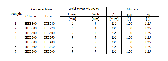
Ai fini del confronto, la sezione trasversale della colonna è stata impostata su HEB300 e la sezione trasversale della trave è stata variabile. Tutti i materiali utilizzati erano S235.
\[ \textsf{\textit{\footnotesize{Tab. 10.1.2 Panoramica sperimentale}}}\]
\[ \textsf{\textit{\footnotesize{Tab. 10.1.3 Panoramica sperimentale}}}\]

\[ \textsf{\textit{\footnotesize{Fig. 1 Verifica del CBFEM rispetto al CM}}}\]
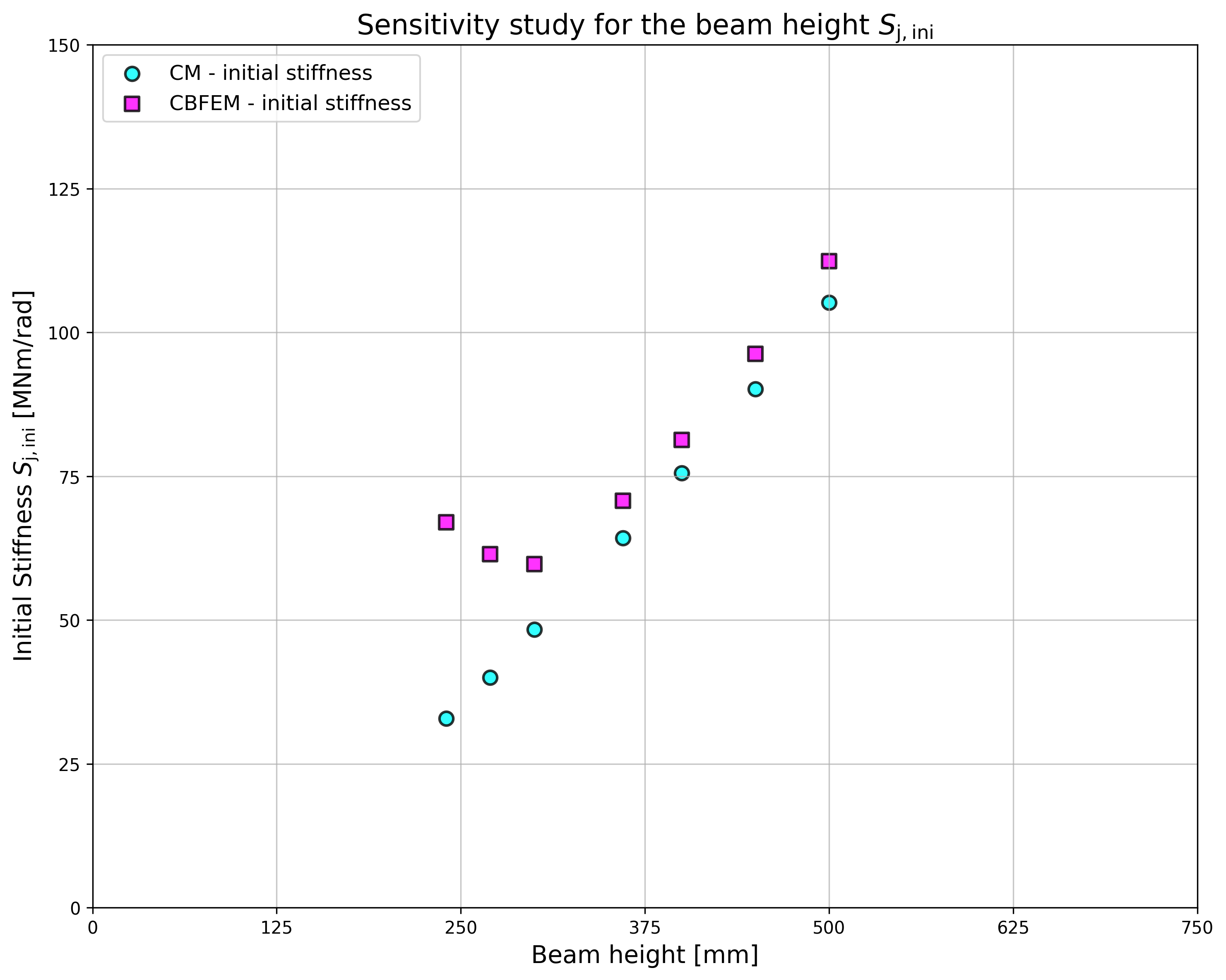
\[ \textsf{\textit{\footnotesize{Fig. 2 Studio di sensibilità della sezione trasversale della trave IPE}}}\]
Verifica della rigidezza
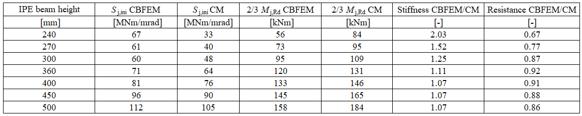
La rigidezza rotazionale calcolata con CBFEM è confrontata con il CM. Il confronto mostra una buona concordanza nella rigidezza iniziale e nella corrispondenza del comportamento del giunto. Le rigidezze calcolate con CBFEM e CM sono riassunte nella Tab. 10.1.3.
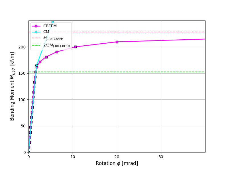
È preparato un confronto del comportamento globale di un giunto a momento saldato di gronda descritto da un diagramma momento-rotazione. Il giunto viene analizzato e viene calcolata la rigidezza della trave collegata. La caratteristica principale è la rigidezza iniziale calcolata a 2/3Mj,Rd, dove Mj,Rd è la resistenza di progetto a momento del giunto. Il diagramma momento-rotazione è mostrato nella Fig. 10.1.1.
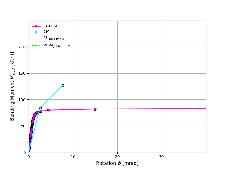
\[ \textsf{\textit{\footnotesize{Fig. 3 Diagramma momento-rotazione per un giunto a momento saldato di gronda, IPE240}}}\]
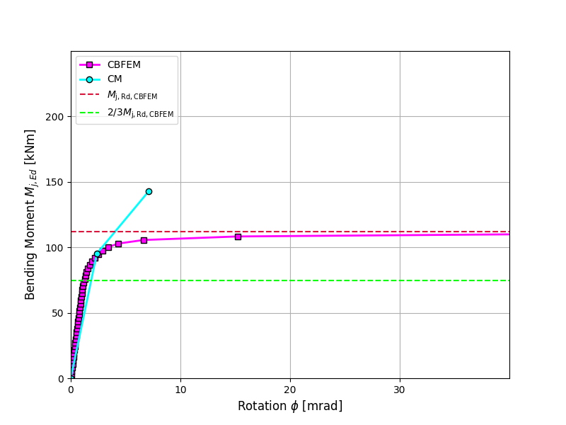
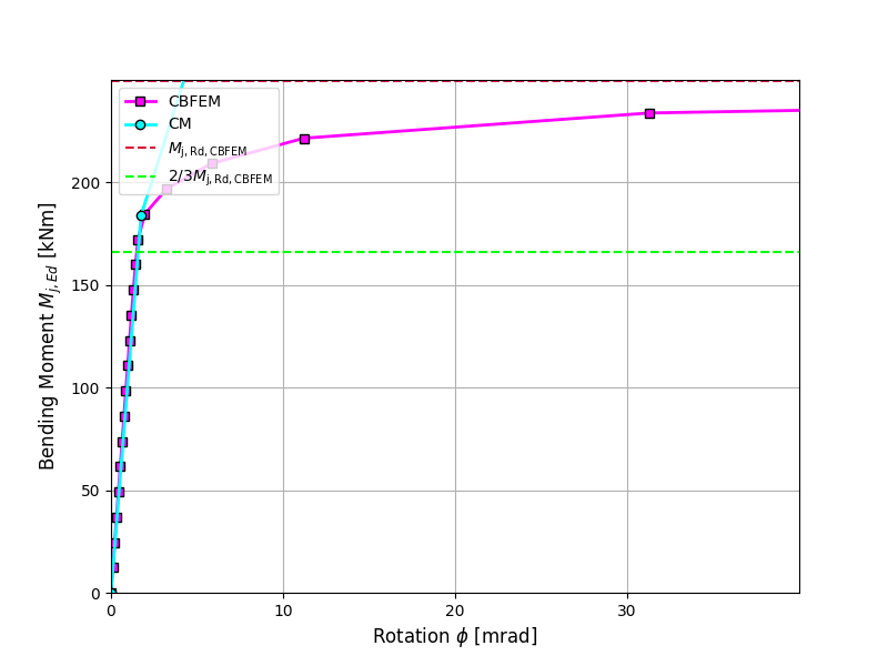
\[ \textsf{\textit{\footnotesize{Fig. 4 Diagramma momento-rotazione per un giunto a momento saldato di gronda, IPE270}}}\]
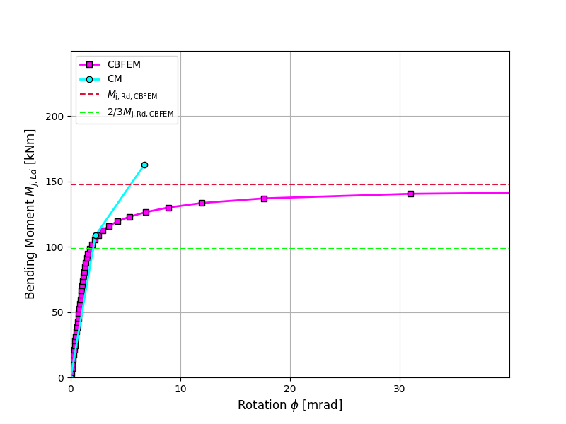
\[ \textsf{\textit{\footnotesize{Fig. 5 Diagramma momento-rotazione per un giunto a momento saldato di gronda, IPE300}}}\]

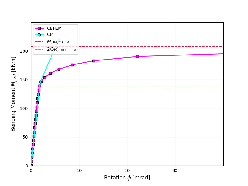
\[ \textsf{\textit{\footnotesize{Fig. 6 Diagramma momento-rotazione per un giunto a momento saldato di gronda, IPE360}}}\]
\[ \textsf{\textit{\footnotesize{Fig. 7 Diagramma momento-rotazione per un giunto a momento saldato di gronda, IPE400}}}\]
\[ \textsf{\textit{\footnotesize{Fig. 8 Diagramma momento-rotazione per un giunto a momento saldato di gronda, IPE450}}}\]
\[ \textsf{\textit{\footnotesize{Fig. 9 Diagramma momento-rotazione per un giunto a momento saldato di gronda, IPE500}}}\]
Caso di riferimento
Dati di input
Trave e colonna
- Acciaio S235
- Colonna HEB 300
- Trave IPE 400
- Spessore di gola della saldatura dell'ala af = 9 mm
- Spessore di gola della saldatura dell'anima aw = 5 mm
- Eccentricità della colonna s = 150 mm
- Saldatura a doppio cordone d'angolo
Risultati
- Resistenza di progetto \(M_\mathrm{j,Rd}= 199 \quad \mathrm{kNm}\)
- Carico \(M_\mathrm{j,Ed}=2/3M_\mathrm{j,Rd}= 133\quad \mathrm{kNm}\)
- Rigidezza rotazionale secante \(S_\mathrm{j,ini}= 81.3\quad \mathrm{MNm/rad}\)
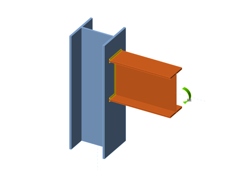
\[ \textsf{\textit{\footnotesize{Fig. 10 Caso di riferimento per il giunto a momento saldato di gronda (IPE 400 su HEB 300)}}}\]