
Rigiditatea la încovoiere a îmbinării sudate a secțiunilor deschise
Descriere
Predicția rigidității de rotație este descrisă pe o îmbinare sudată de colț cu moment încovoietor. Se studiază o îmbinare sudată a unui stâlp cu secțiune deschisă HEB și a unei grinzi IPE, iar comportamentul îmbinării este descris printr-o diagramă moment-rotație. Rezultatele modelului analitic prin metoda componentelor (CM) sunt comparate cu rezultatele numerice obținute prin metoda elementelor finite bazată pe componente (CBFEM). Este disponibil un caz de referință.
Model analitic
Rigiditatea de rotație a unei îmbinări trebuie determinată din deformația componentelor sale de bază, care sunt reprezentate prin coeficientul de rigiditate ki. Rigiditatea de rotație a îmbinării Sj se obține din:
\[ S_j = \frac{E z^2}{\mu \Sigma_i \frac{1}{k_i}} \]
unde:
- ki este coeficientul de rigiditate pentru componenta i a îmbinării;
- z este brațul de pârghie; a se vedea 6.2.7;
- μ este raportul de rigiditate; a se vedea 6.3.1.
Componentele îmbinării luate în considerare în acest exemplu sunt panoul inimii stâlpului la forfecare k1, inima stâlpului la compresiune k2, și inima stâlpului la întindere k3. Coeficienții de rigiditate sunt definiți în Tabelul 6.11 din EN 1993-1-8:2005. Rigiditatea inițială Sj,ini se obține pentru un moment Mj,Ed ≤ 2/3 Mj,Rd.
\[S_j = \frac{E \, z^{2}}{\frac{1}{k_1} + \frac{1}{k_2} + \frac{1}{k_3}}\]
\[S_{j,\text{ini}} = \frac{S_j}{1.5^{\psi}}\]
unde
\(S_{j}\) — rigiditatea de rotație a îmbinării
\(\psi\) = 2,7 — EN 1993-1-8 tabelul 6.8
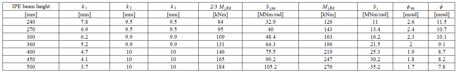
În exemplu, o grindă cu secțiune deschisă IPE 400 este sudată la un stâlp HEB 300. Tălpile grinzii sunt conectate la talpa stâlpului prin suduri cu grosimea de calcul a cordonului de 9 mm. Inima grinzii este conectată prin suduri cu grosimea de calcul a cordonului de 5 mm. Se consideră distribuția plastică a tensiunilor în suduri. Materialul grinzii și al stâlpului este S235. Rezistența de calcul este limitată de componentele panoul stâlpului la forfecare și panoul stâlpului la compresiune transversală. Coeficienții de rigiditate calculați ai componentelor de bază, rigiditatea inițială, rigiditatea la rezistența de calcul și rotația grinzii sunt rezumate în Tab. 10.1.1.
\[ \textsf{\textit{\footnotesize{Tab. 10.1.1 Rezultatele modelului analitic}}}\]
Model numeric
Informații detaliate despre predicția rigidității în CBFEM pot fi găsite în capitolul 3.9. Aceeași îmbinare sudată de colț cu moment încovoietor este modelată, iar rezultatele sunt prezentate în Tab. 10.1.2. Rezistența de calcul este atinsă la o deformație plastică de 5% în componenta inima stâlpului la întindere. Analizele CBFEM permit calculul rigidității de rotație în orice etapă de încărcare.
Prezentare generală experimentală
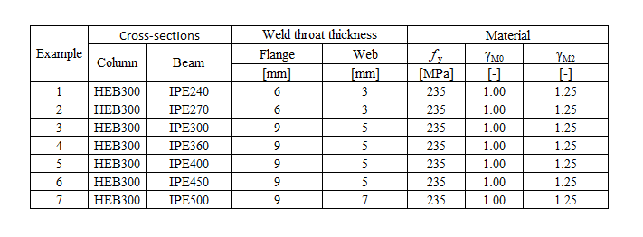
În scopul comparației, secțiunea transversală a stâlpului a fost stabilită la HEB300, iar secțiunea transversală a grinzii a fost variabilă. Toate materialele utilizate au fost S235.
\[ \textsf{\textit{\footnotesize{Tab. 10.1.2 Prezentare generală experimentală}}}\]
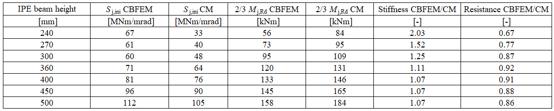
\[ \textsf{\textit{\footnotesize{Tab. 10.1.3 Prezentare generală experimentală}}}\]

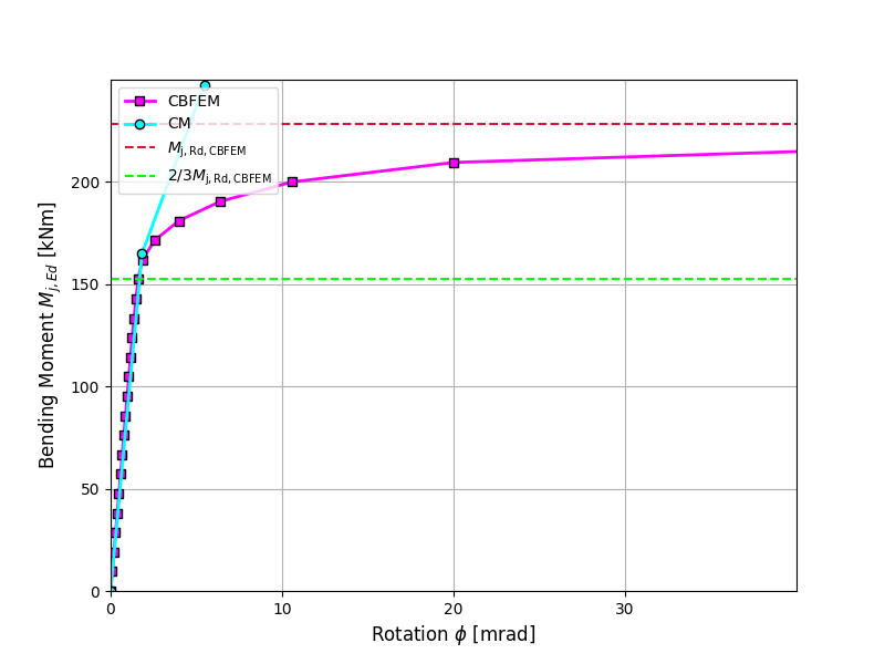
\[ \textsf{\textit{\footnotesize{Fig. 1 Verificarea CBFEM față de CM}}}\]
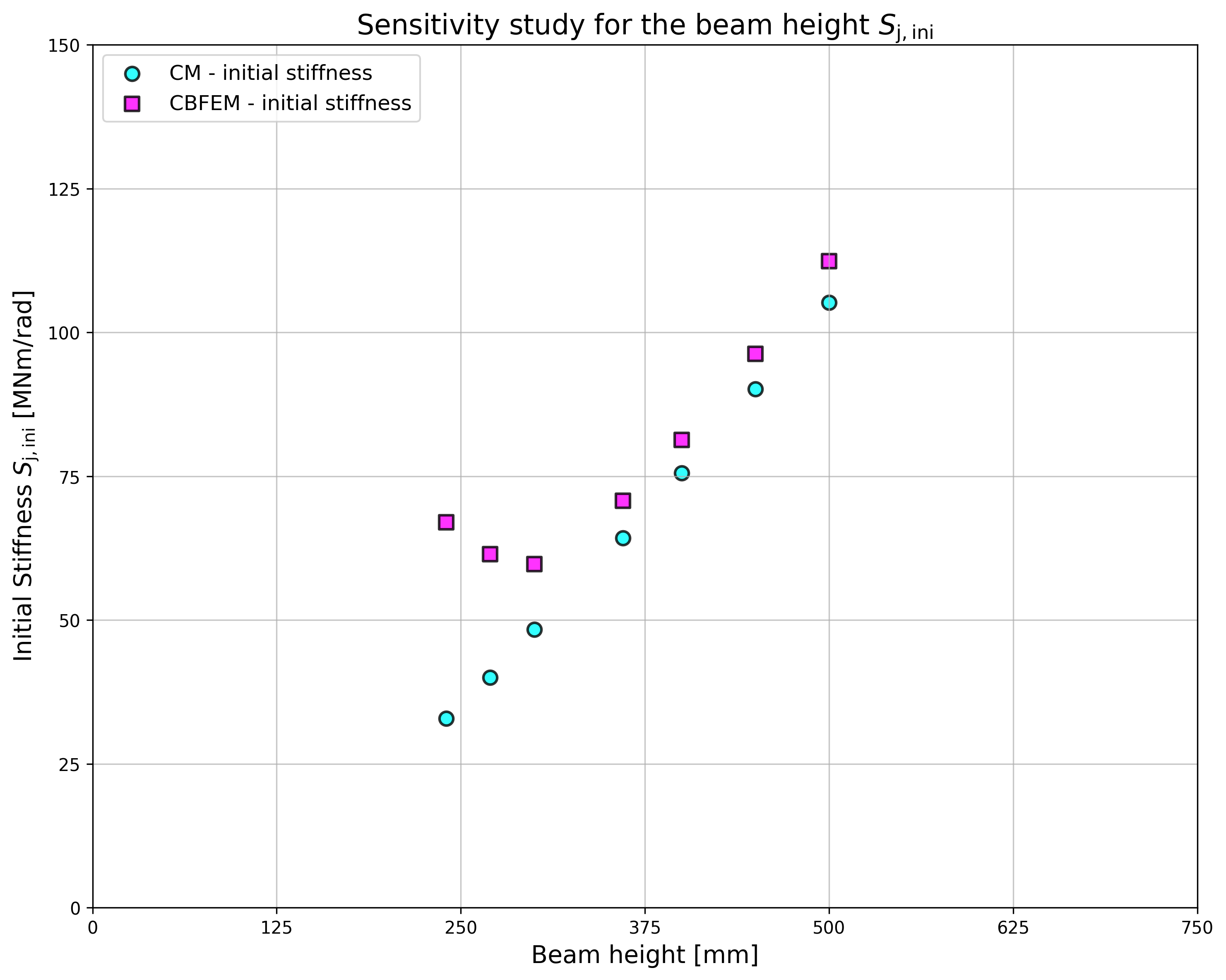
\[ \textsf{\textit{\footnotesize{Fig. 2 Studiu de sensibilitate al secțiunii transversale a grinzii IPE}}}\]
Verificarea rigidității
Rigiditatea de rotație calculată prin CBFEM este comparată cu CM. Comparația arată o bună concordanță a rigidității inițiale și corespondența comportamentului îmbinării. Rigiditatea calculată prin CBFEM și CM este rezumată în Tab. 10.1.3.
Este pregătită o comparație a comportamentului global al unei îmbinări sudate de colț cu moment încovoietor, descrisă printr-o diagramă moment-rotație. Îmbinarea este analizată și se calculează rigiditatea grinzii conectate. Caracteristica principală este rigiditatea inițială calculată la 2/3Mj,Rd, unde Mj,Rd este rezistența de calcul la moment a îmbinării. Diagrama moment-rotație este prezentată în Fig. 10.1.1.
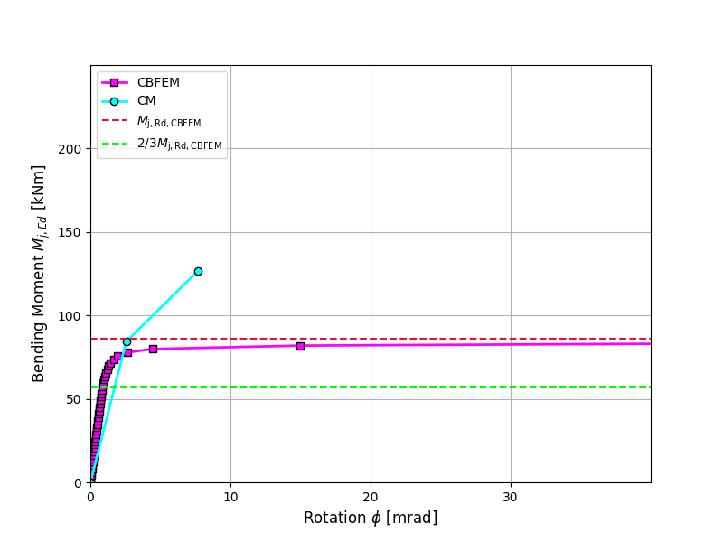
\[ \textsf{\textit{\footnotesize{Fig. 3 Diagrama moment-rotație pentru o îmbinare sudată de colț cu moment încovoietor, IPE240}}}\]
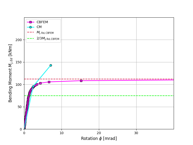
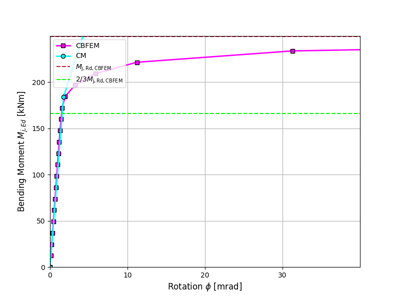
\[ \textsf{\textit{\footnotesize{Fig. 4 Diagrama moment-rotație pentru o îmbinare sudată de colț cu moment încovoietor, IPE270}}}\]
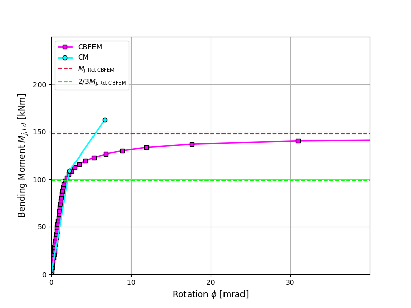
\[ \textsf{\textit{\footnotesize{Fig. 5 Diagrama moment-rotație pentru o îmbinare sudată de colț cu moment încovoietor, IPE300}}}\]

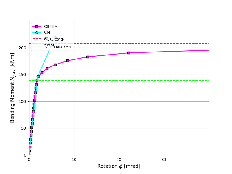
\[ \textsf{\textit{\footnotesize{Fig. 6 Diagrama moment-rotație pentru o îmbinare sudată de colț cu moment încovoietor, IPE360}}}\]
\[ \textsf{\textit{\footnotesize{Fig. 7 Diagrama moment-rotație pentru o îmbinare sudată de colț cu moment încovoietor, IPE400}}}\]
\[ \textsf{\textit{\footnotesize{Fig. 8 Diagrama moment-rotație pentru o îmbinare sudată de colț cu moment încovoietor, IPE450}}}\]
\[ \textsf{\textit{\footnotesize{Fig. 9 Diagrama moment-rotație pentru o îmbinare sudată de colț cu moment încovoietor, IPE500}}}\]
Caz de referință
Date de intrare
Grindă și stâlp
- Oțel S235
- Stâlp HEB 300
- Grindă IPE 400
- Grosimea de calcul a cordonului de sudură la talpă af = 9 mm
- Grosimea de calcul a cordonului de sudură la inimă aw = 5 mm
- Excentricitatea stâlpului s = 150 mm
- Sudură de colț dublă
Date de ieșire
- Rezistența de calcul \(M_\mathrm{j,Rd}= 199 \quad \mathrm{kNm}\)
- Încărcarea \(M_\mathrm{j,Ed}=2/3M_\mathrm{j,Rd}= 133\quad \mathrm{kNm}\)
- Rigiditatea de rotație secantă \(S_\mathrm{j,ini}= 81.3\quad \mathrm{MNm/rad}\)
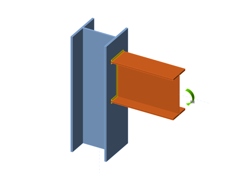
\[ \textsf{\textit{\footnotesize{Fig. 10 Caz de referință pentru îmbinarea sudată de colț cu moment încovoietor (IPE 400 la HEB 300)}}}\]