Egyedi keresztmetszetű kapcsolat merevségelemzése (EN)
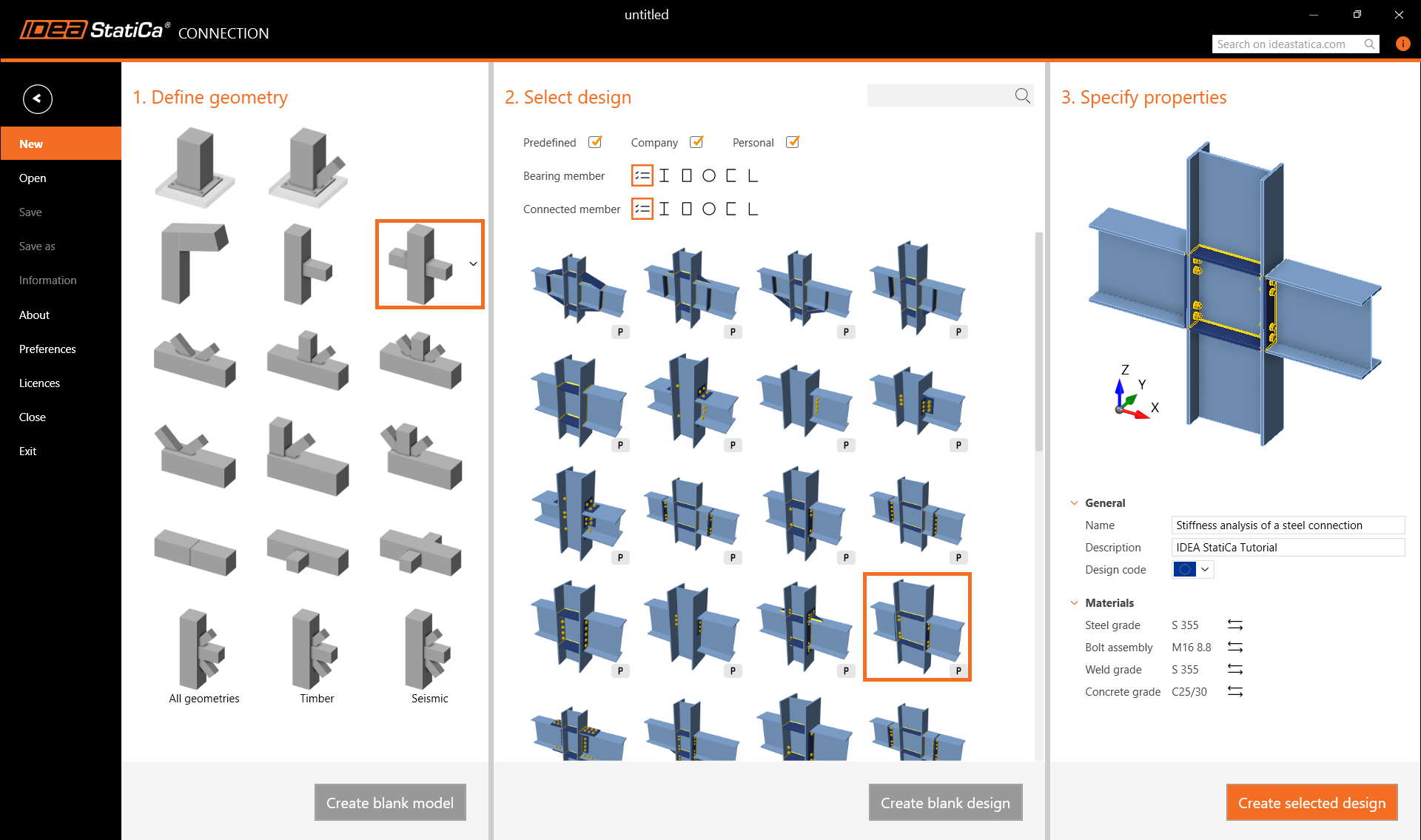
1 Új projekt
Indítsa el az IDEA StatiCa (töltse le a legújabb verziót) programot, és válassza a Connection alkalmazást.
Hozzon létre egy új projektet a kívánt tervhez legközelebb álló sablon kiválasztásával a varázslóból. Adja meg a nevet, válassza ki az S355 acélminőséget, a Eurocode tervezési szabványt, majd kattintson a Create project gombra.
2 Geometria
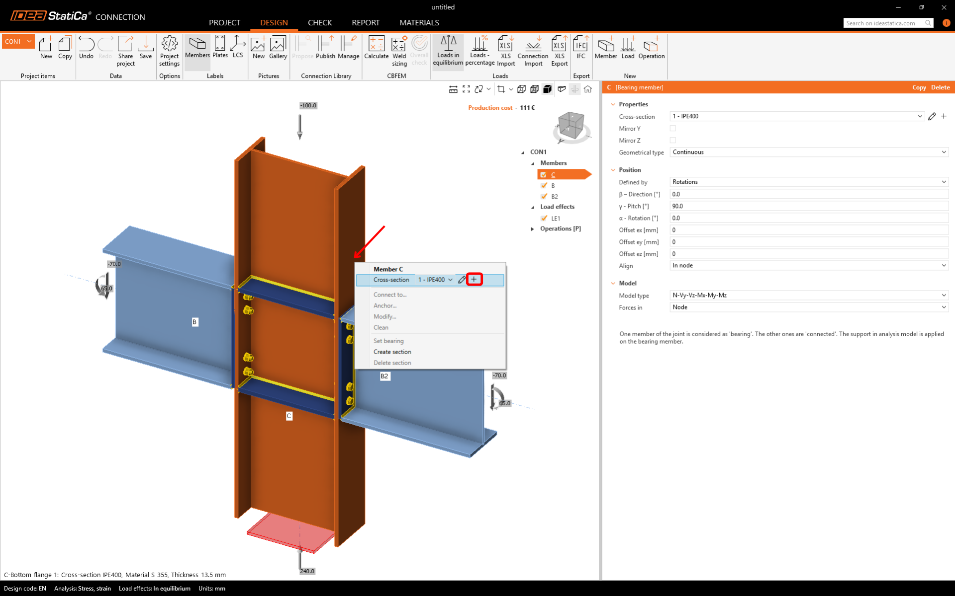
Kezdjük az egyedi keresztmetszet meghatározásával, amelyet három különböző szelvényből építünk fel.
Kattintson jobb gombbal a C függőleges szerkezeti elemen, és nyissa meg az elérhető műveleteket tartalmazó helyi menüt. A Plus gombbal adjon hozzá egy új keresztmetszetet.
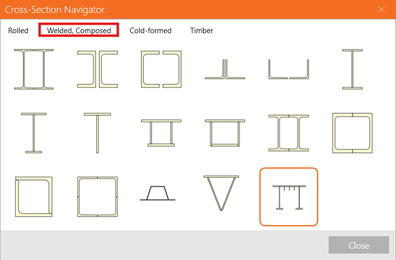
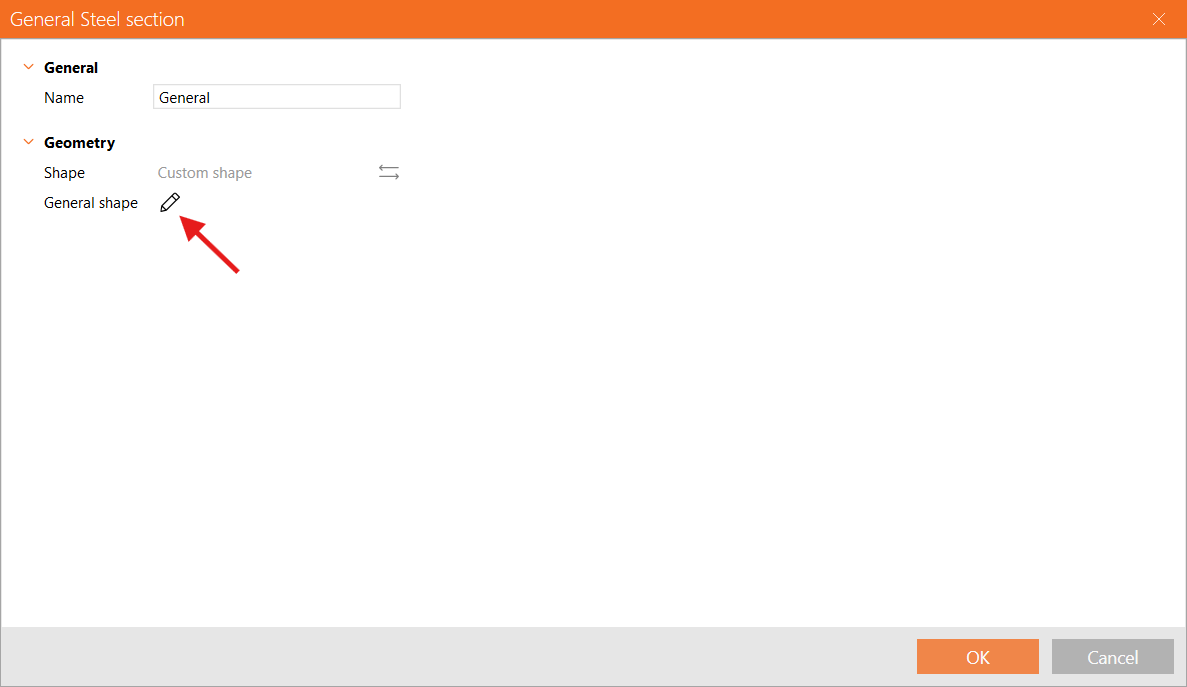
Lépjen a Welded, Composed fülre, és válassza a General steel cross-section lehetőséget a felhasználó által meghatározott alakzat hozzáadásához.
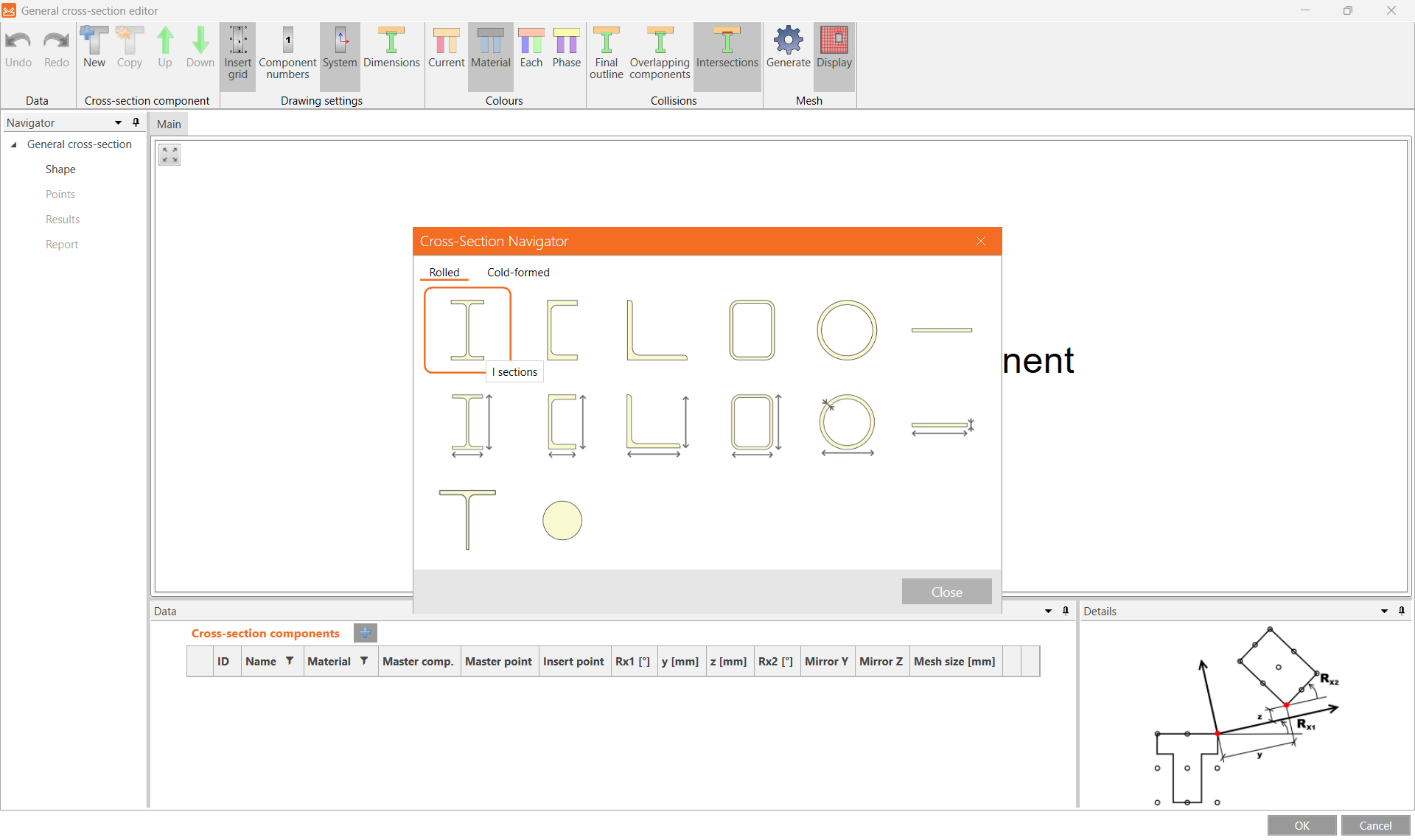
A Cross-section editor szerkesztőben kezdje egy új I-szelvény hozzáadásával.
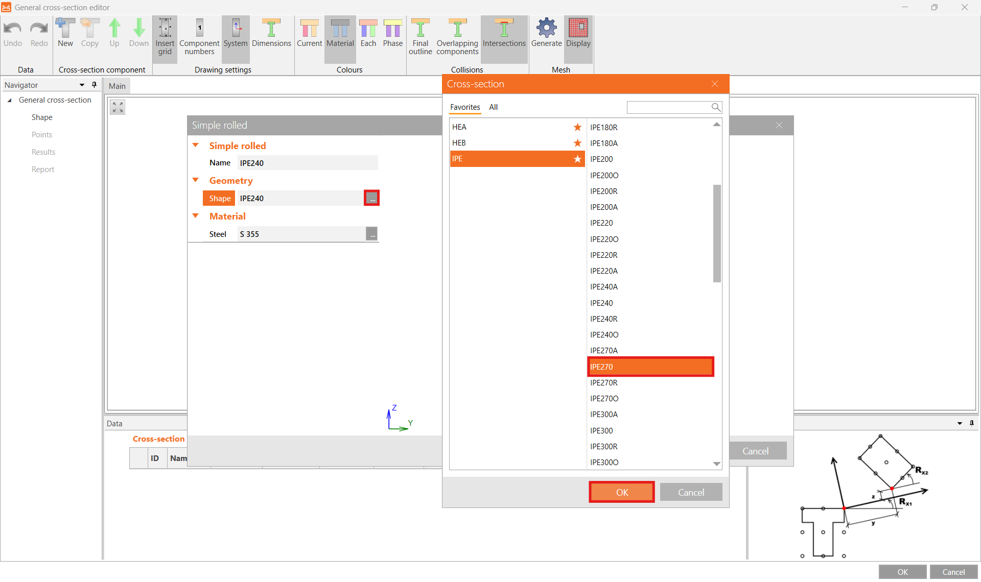
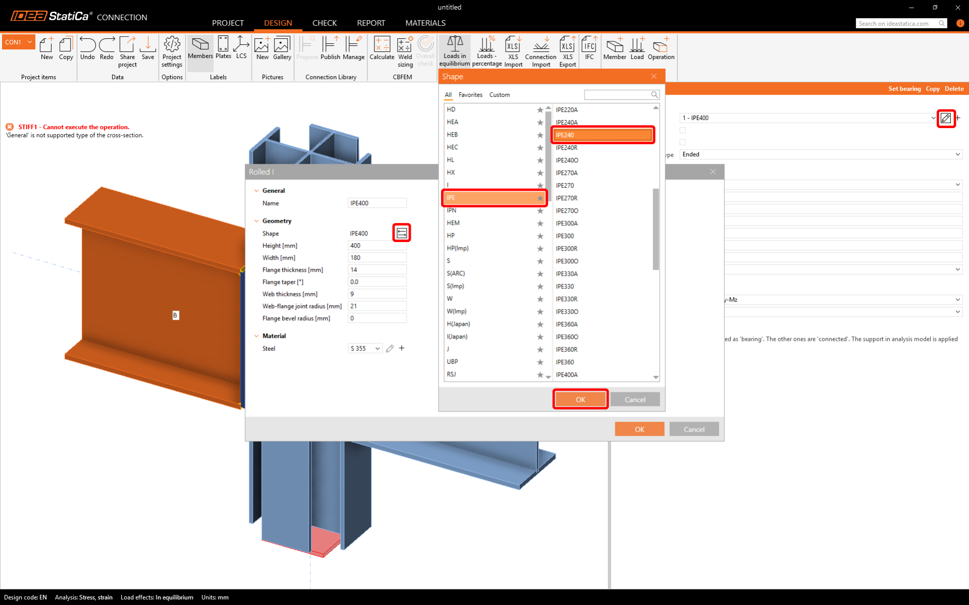
Majd módosítsa az előre kiválasztott szelvényt IPE270-re.
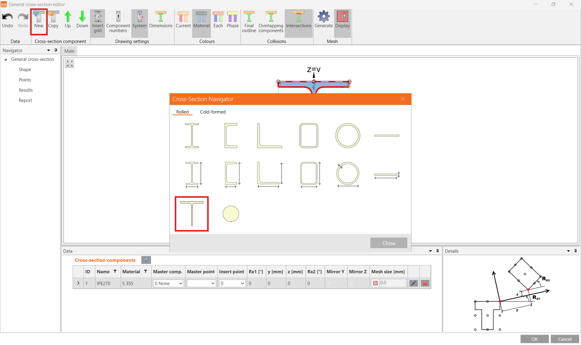
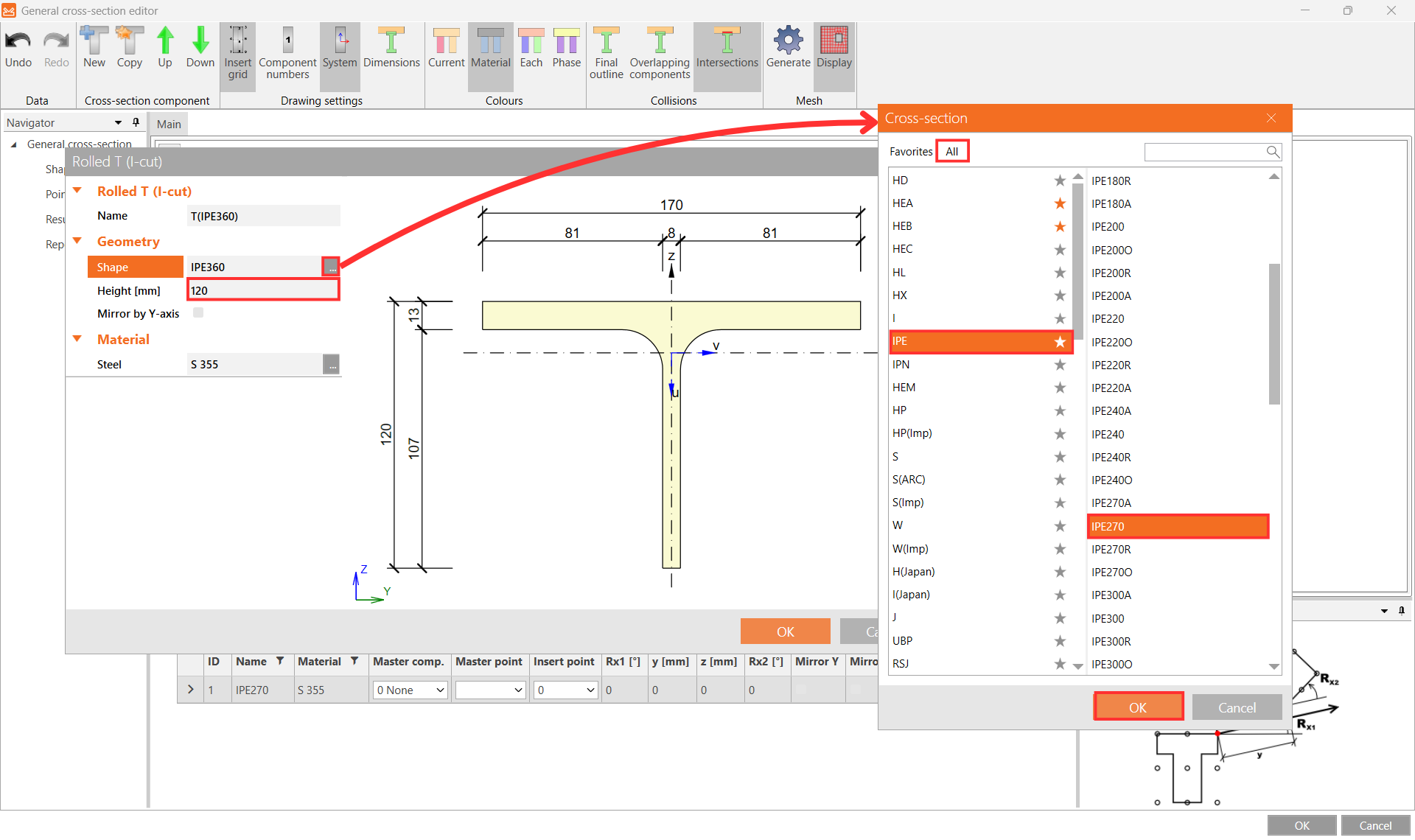
Ezután kattintson a New gombra egy újabb szelvény hozzáadásához, és válassza a Sections T (I-cut) lehetőséget.
Az Shape mezőnél válassza az IPE270 szelvényt a keresztmetszet-könyvtárból, adjon meg 120 mm értéket a Height mezőbe, majd erősítse meg az OK gombbal.
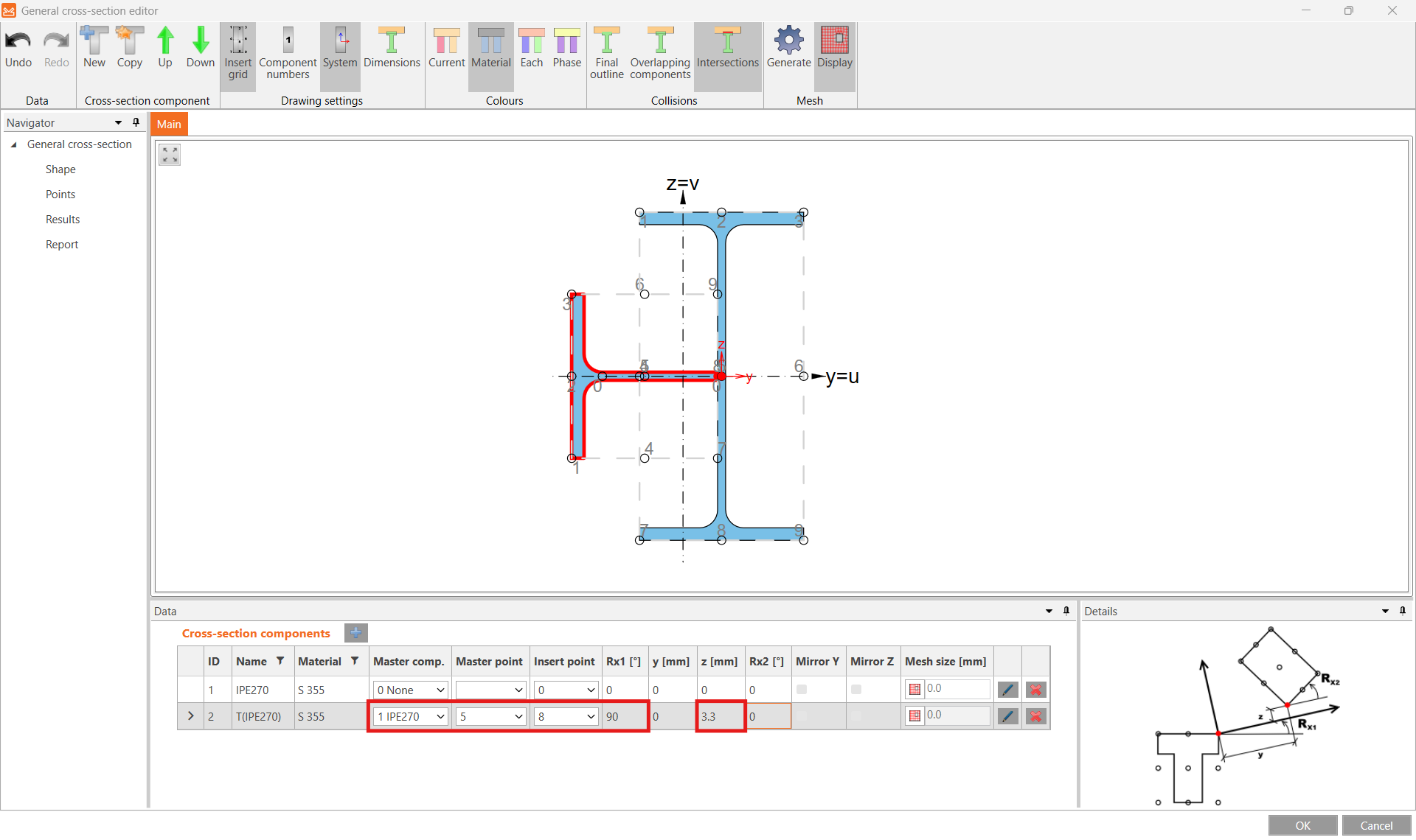
Most helyezze el a T szelvényt a megfelelő Master component, Master point és Insert point kiválasztásával, majd adjon meg 90° elforgatást az Rx1 irányban és 3,3 mm eltolást a z irányban.
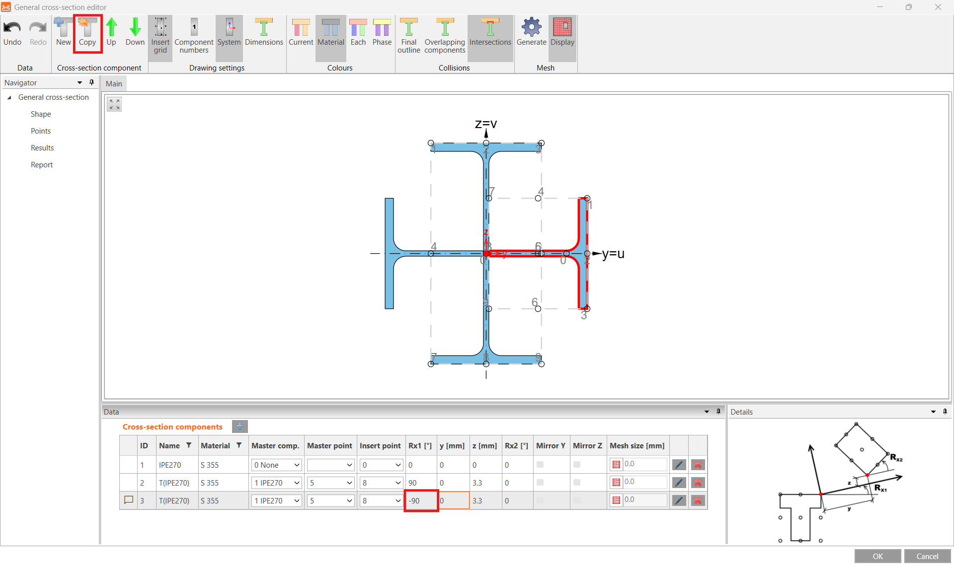
Készítsen egy Copy másolatot erről a szelvényrészről, módosítsa az Rx1 elforgatást -90°-ra, majd zárja be a szerkesztőt az OK gombbal.
Az általános keresztmetszet-szerkesztőről bővebben a Hogyan hozzunk létre és használjunk egyedi keresztmetszetet című cikkben olvashat.
3 Teherhatások
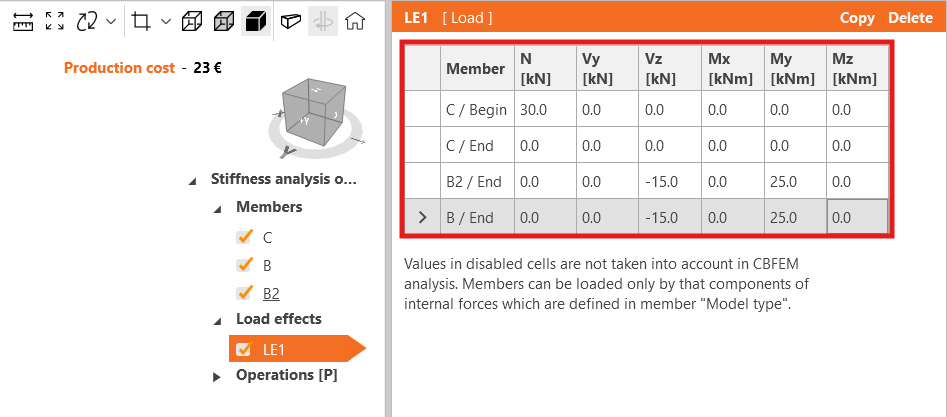
Módosítsa a LE1 teherhatás értékeit megfelelően.
4 Tervezés
Állítsa a csatlakozó gerendákat IPE240 szelvényre.
Módosítsa a Template 1 [P] paramétereit, bontsa szét (Explode), és kapcsolja ki a merevítőket.

5 Számítás és ellenőrzés
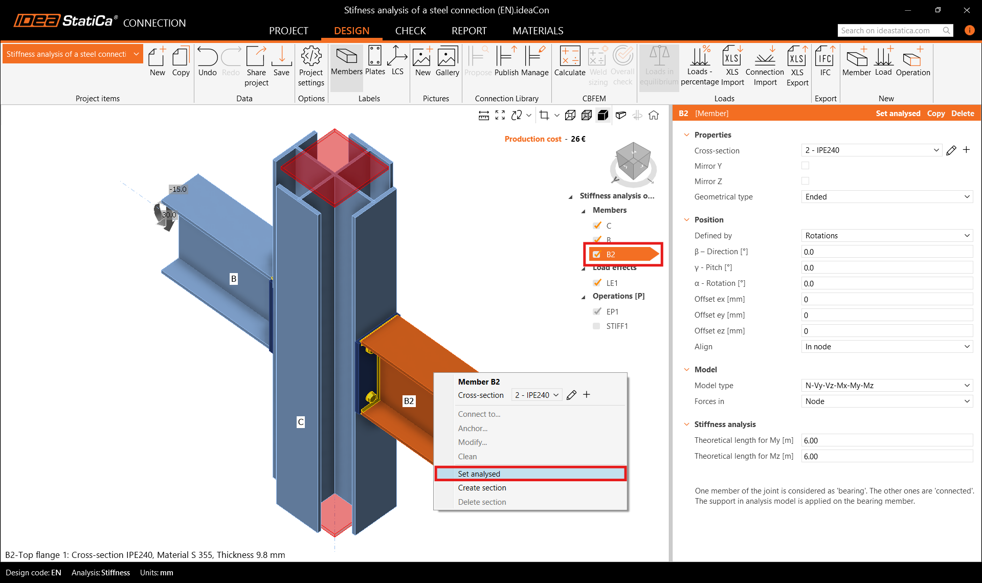
Válassza ki a CON1 projektelmet, és váltson az elemzés típusát Stiffness analysis (ST) módra.

Ellenőrizze, hogy a B2 szerkezeti elem van-e beállítva Analysed member (vizsgált elem) ként (a szerkezeti elemek listájában aláhúzva jelenik meg, és az elem tulajdonságaiban is látható), vagy állítsa be vizsgált elemként a jobb gombos menün keresztül. Ezután futtassa a Calculation számítást.
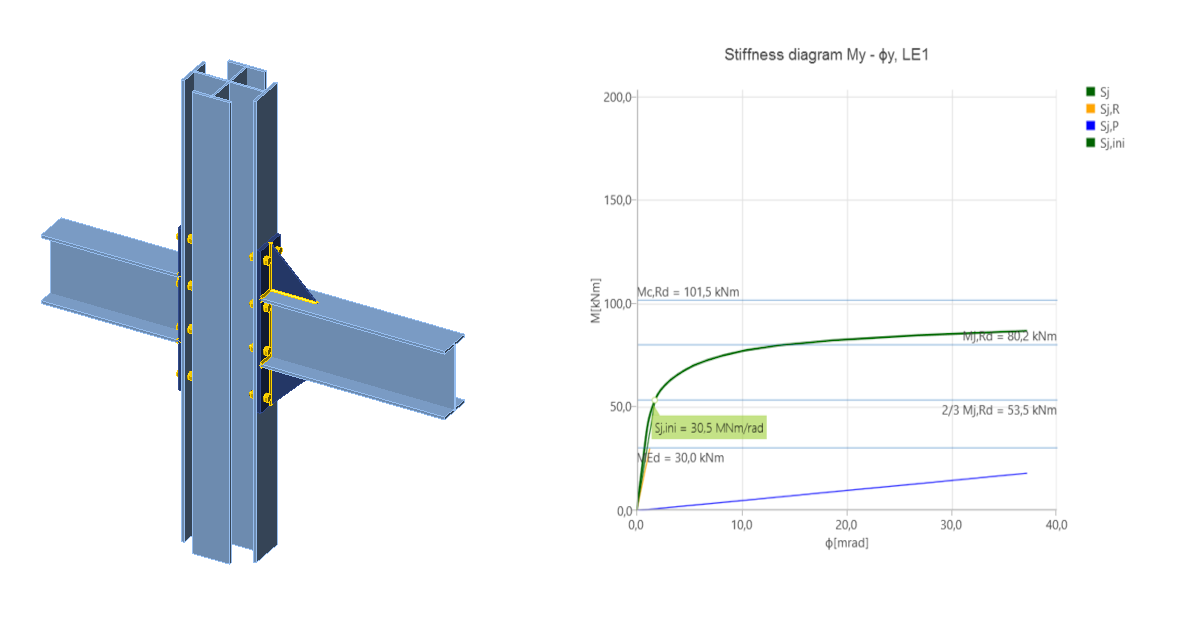
Lépjen a Check fülre, és kapcsolja be a Plastic strain, Bolt forces, Mesh és Deformed megjelenítési lehetőségeket a kapcsolat viselkedésének megtekintéséhez. A Rotational stiffness fülön leolvasható az osztály mint Semi-rigid (félmerev), valamint a kezdeti forgási merevség Sj,ini értéke.

Megjegyzés: A „Theoretical length for My, Mz" és az eredmények mélyebb megértéséhez lásd a Stiffness analysis cikket és az Theoretical Background fejezet Stiffness analysis and deformation capacity of steel joints részét.
6 A kapcsolat optimalizálása
Lépjen vissza a Design fülre a kapcsolat optimalizálásához, hogy merev kapcsolatot érjen el.

Győződjön meg arról, hogy a merevítő művelet inaktív, majd módosítsa az EP1 homloklemez vastagságát, méreteit és a csavarok elhelyezkedését.

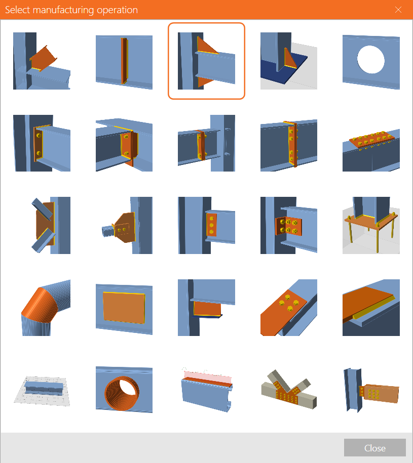
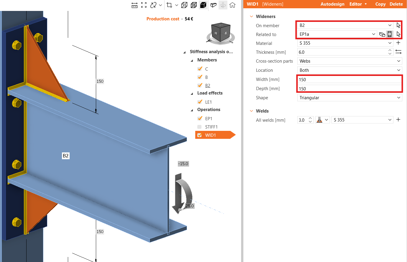
Adjon hozzá egy új Widener műveletet.
Váltsa a Related to elemet Plate értékre (a EP1a lemez automatikusan kiválasztódik), majd adjon meg 150 mm értéket mind a Width, mind a Depth mezőbe.
Futtassa újra a merevségelemzést, és a Check fülön ellenőrizze, hogy az osztály Rigid (merev) lett, és a kezdeti forgási merevség Sj,ini értéke megnőtt.

7 Jelentés
Utolsó lépésként lépjen a Report fülre. Az IDEA StatiCa teljes mértékben testreszabható jelentést kínál, amely kinyomtatható vagy szerkeszthető formátumban menthető.

Megtervezte és szabványellenőrizte az acél szerkezeti csomópontot az Eurocode (EN) szerint.
8 Magyarázó videók
További információkért olvassa el az Elméleti háttér cikket.