Pourquoi la limite de déformation plastique de 5 % est-elle utilisée dans le diagramme de matériau pour l'AISC ?
Méthodes courantes
Tout ingénieur structure a l'habitude d'utiliser la limite d'élasticité comme valeur limite de vérification normative, car pratiquement toutes les normes et codes de calcul reposent sur cette approche.
Néanmoins, cela s'applique au comportement purement élastique du matériau. Cela peut conduire à un dimensionnement conservateur et parfois à un surdimensionnement inutile de la structure, entraînant une consommation accrue de matériaux.
Cependant, le comportement réel de l'acier est différent, et il est acceptable de supposer un comportement plastique du matériau après dépassement de la limite d'élasticité.
IDEA StatiCa et la méthode CBFEM
La Méthode des Éléments Finis basée sur les Composants (CBFEM) est une synergie entre la Méthode des Composants et l'analyse par Éléments Finis.
La vérification normative d'un assemblage selon la méthode standard des composants et selon le CBFEM utilisé dans IDEA StatiCa Connection est basée sur la vérification de toutes les parties de l'assemblage – les composants. Les composants peuvent être des boulons, ancrages, soudures, plaques, et du béton au niveau de la fondation.
CBFEM décompose l'ensemble de l'assemblage en composants séparés mentionnés ci-dessus. Le modèle d'analyse est ensuite créé automatiquement par le logiciel à partir de chaque composant.
Toutes les plaques en acier, telles que les semelles ou les âmes des sections transversales, les raidisseurs, les nervures, les jarrets, etc., sont modélisées par des éléments finis. La Méthode des Éléments Finis est largement acceptée en ingénierie structurelle et fournit des résultats très bons et fiables.
Le comportement du matériau est basé sur le critère de plasticité de von Mises. Il est supposé élastique avant d'atteindre la valeur de calcul de la limite d'élasticité fyd.
Le critère d'état limite ultime pour les zones non susceptibles de flambement est l'atteinte de la valeur limite de la déformation principale membranaire. Une valeur de 5 % est recommandée (par ex. EN 1993-1-5, Ann. C, Par. C.8, Note 1).
ANSI/AISC 360-16 utilise une approche différente. Au Chapitre B – Exigences de calcul, il est indiqué : « Résistance de l'assemblage. La résistance d'un assemblage est le moment maximal qu'il est capable de reprendre, Mn, comme indiqué à la Figure C-B3.2. La résistance d'un assemblage peut être déterminée sur la base d'un modèle d'état limite ultime de l'assemblage, ou à partir d'essais physiques. Si la réponse moment-rotation ne présente pas de charge maximale, la résistance peut être prise comme le moment à une rotation de 0,02 rad (Hsieh et Deierlein, 1991 ; Leon et al., 1996). »

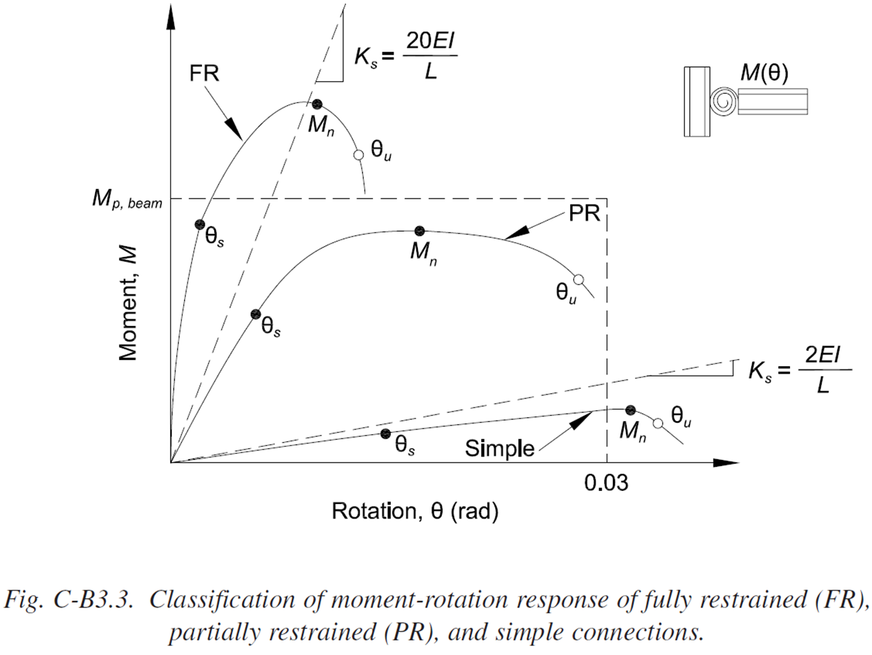
Les figures sont extraites de ANSI/AISC 360-16, Comm. B3, p. 332, 333.
Un exemple d'assemblage soudé dans IDEA StatiCa est présenté :


La résistance en flexion de calcul de cet assemblage, conformément à cet article de l'AISC 360, est déterminée comme le moment fléchissant à la rotation de 20 mrad (MRd = 408,5 kip-in). Cette résistance est pratiquement égale à la résistance en flexion déterminée en limitant la déformation plastique à 5 % comme suggéré par EN 1993-1-5 (MRd = 402,5 kip-in).
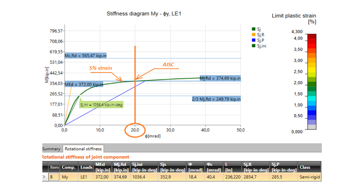
Un autre exemple d'assemblage boulonné montre des résultats similaires :


De même, la résistance déterminée par une rotation de 20 mrad (MRd = 372 kip-in) coïncide étroitement avec la résistance déterminée en limitant la déformation plastique à 5 % (MRd = 374,7 kip-in).
Conclusion
ANSI/AISC 360 laisse la modélisation par éléments finis (voir Annexe 1 – Calcul par analyse avancée et Chapitre B – Exigences de calcul – 4. Calcul des assemblages et des appuis – Analyse structurelle) au jugement de l'ingénieur. L'utilisation d'un diagramme matériau bilinéaire élastique-plastique pour les plaques en acier et la limitation de la déformation plastique constituent une approche simple et raisonnable permettant de résoudre tous les types d'assemblages soumis à des chargements généraux. Les résultats coïncident étroitement avec l'approche suggérée spécifiquement par ANSI/AISC 360.
La limite de déformation plastique peut être modifiée dans la Configuration du code, bien que les études de vérification aient été réalisées avec une valeur recommandée de 5 %. Cette valeur a généralement un faible effet sur la résistance de l'assemblage. La différence de résistance au moment fléchissant entre une déformation limite de 2 % et une déformation limite de 10 % n'est que de 7 % dans le second exemple d'assemblage boulonné.
Références
ANSI/AISC 360-16 (2016), An American National Standard – Specification for Structural Steel Buildings, AISC, Chicago, 676 p.
EN1993-1-5 (2006), Eurocode 3 : Calcul des structures en acier - Partie 1-5 : Règles générales - Plaques planes, CEN, Bruxelles, 53 p.
Hsieh, S.H. et Deierlein, G.G. (1991), « Nonlinear Analysis of Three-Dimensional Steel Frames with Semi-Rigid Connections », Computers and Structures, Elsevier, Vol. 41, No. 5, pp. 995–1 009.
Leon, R.T. (1994), « Composite Semi-Rigid Construction », Engineering Journal, AISC, Vol. 31. No. 2, pp. 57–67.