Tornillos y uniones atornilladas
Modelo de tornillo según CBFEM
IDEA StatiCa dispone de un método único en su solver, el Método de los Elementos Finitos basado en Componentes (CBFEM). El modelo de tornillo utilizado en CBFEM se describe y verifica según varios códigos de diseño de acero. La resistencia a la carga y la capacidad de deformación también se comparan con los principales programas de investigación experimental.
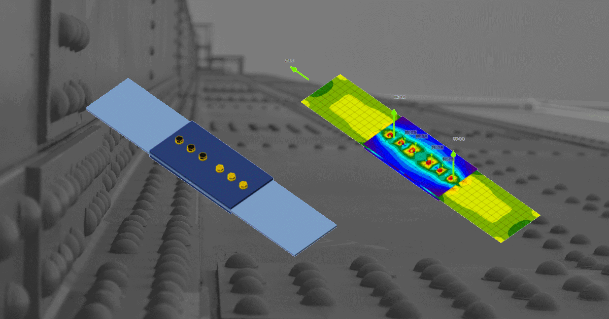
En el Método de los Elementos Finitos basado en Componentes (CBFEM), el tornillo con su comportamiento a tracción, cortante y aplastamiento es el componente descrito por muelles no lineales dependientes. El tornillo a tracción se describe mediante un muelle con su rigidez axial inicial, resistencia de cálculo, inicio de la plastificación y capacidad de deformación. Para el inicio de la plastificación y la capacidad de deformación, se asume que la deformación plástica ocurre únicamente en la parte roscada del vástago del tornillo.
En nuestros Fundamentos Teóricos, puede encontrar más información sobre cómo el método CBFEM describe y verifica los tornillos. Si desea saber un poco más sobre CBFEM en general, los Fundamentos teóricos generales son definitivamente el mejor punto de partida.
Tornillos según códigos de diseño
Veamos cómo CBFEM aborda los tornillos desde el punto de vista de los distintos códigos de diseño. Hasta ahora, IDEA StatiCa admite ocho códigos de diseño en los que se resuelve el diseño y/o el detallado de tornillos y tornillos pretensados.
Verificación normativa de tornillos y tornillos pretensados según Eurocódigo
La rigidez inicial y la resistencia de cálculo de los tornillos a cortante se modelan en CBFEM según los apartados 3.6 y 6.3.2 de EN 1993-1-8. El muelle que representa el aplastamiento y la tracción tiene un comportamiento bilineal fuerza-deformación con rigidez inicial y resistencia de cálculo según los apartados 3.6 y 6.3.2 de EN 1993-1-8.
Detallado
La verificación normativa de los tornillos se realiza si la opción está seleccionada en la configuración del código. Se comprueban las distancias desde el centro del tornillo a los bordes de la placa y entre tornillos. La distancia al borde e = 1,2 y la separación entre tornillos p = 2,2 se recomiendan en la Tabla 3.3 de EN 1993-1-8. Los usuarios pueden modificar ambos valores en la configuración del código.
Verificación normativa de tornillos y tornillos pretensados según AISC
Las fuerzas en los tornillos se determinan mediante análisis por elementos finitos. Las fuerzas de tracción incluyen las fuerzas de palanca. Las resistencias de los tornillos se verifican según AISC 360 - Capítulo J3.
Detallado
Se comprueba la separación mínima entre tornillos y la distancia desde el centro del tornillo al borde de la parte conectada. La separación mínima de 2,66 veces (editable en la configuración del código) el diámetro nominal del tornillo entre centros de tornillos se verifica según AISC 360-16 – J.3.3. La distancia mínima desde el centro del tornillo al borde de la parte conectada se verifica según AISC 360-16 – J.3.4; los valores se encuentran en las Tablas J3.4 y J3.4M.
Verificación normativa de tornillos y tornillos pretensados según otras normas
- Verificación normativa de tornillos y tornillos pretensados según CISC (Canadá)
- Verificación normativa de tornillos y tornillos pretensados según la norma china (GB)
- Verificación normativa de tornillos según el Código de Hong Kong (HKG)
- Verificación normativa de tornillos pretensados según IS 800 (India)
- Verificación normativa de tornillos y tornillos pretensados según SP (Rusia)
- Verificación normativa de tornillos y tornillos pretensados según AS (Australia)
Detallado de tornillos
Cómo establecer las distancias
Las distancias al borde utilizadas para la resistencia al aplastamiento de los tornillos deben ser relevantes para geometrías generales de placas, placas con aberturas, recortes, etc.
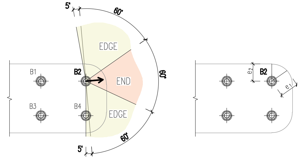
El algoritmo lee la dirección real del vector de fuerza cortante resultante en un tornillo dado y luego calcula las distancias necesarias para la verificación al aplastamiento.
Las distancias al extremo (e1) y al borde (e2) se determinan dividiendo el contorno de la placa en tres segmentos. El segmento de extremo se indica mediante un rango de 60° en la dirección del vector de fuerza. Los segmentos de borde se definen por dos rangos de 65° perpendiculares al vector de fuerza. La distancia más corta desde un tornillo hasta el segmento correspondiente se toma entonces como distancia al extremo o al borde.
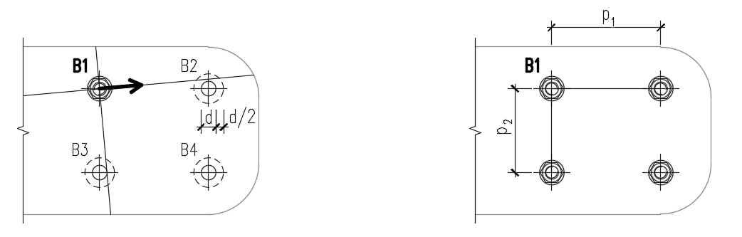
Las distancias de separación entre agujeros de tornillos (p1; p2) se determinan ampliando virtualmente los agujeros de tornillos circundantes en la mitad de su diámetro, trazando luego dos líneas en la dirección y perpendicular al vector de fuerza cortante. Las distancias a los agujeros de tornillos ampliados que son intersectados por estas líneas se consideran entonces como p1 y p2 en el cálculo.
Ejemplos de verificación
Hemos preparado varios ejemplos de verificación para comprobar los resultados en comparación con otros métodos de cálculo.
EN
- Unión atornillada - Empalmes a cortante
- Unión atornillada - Interacción de cortante y tracción
- Junta con cartela – diseño por capacidad
AISC
- Unión de empalme atornillada
- Unión de momento con placa de ala atornillada – LRFD
- Unión de momento con placa de testa extendida – ASD
Tecnología patentada para ingenieros estructurales
¿Sabía que nuestra solución de modelo de tornillo forma parte de una patente estadounidense? Lea aquí nuestra historia de éxito.

Una junta con un solo tornillo - nuestra solución
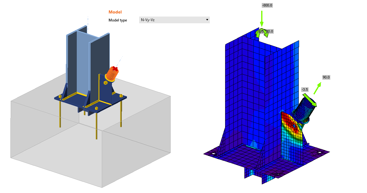
En ocasiones, el ingeniero necesita realizar una junta con un solo tornillo, especialmente cuando se prevé, por ejemplo, una articulación, un arriostramiento, una barra o una diagonal. Para modelar y calcular este tipo de operación, es necesario definir un Tipo de modelo adecuado del elemento. Puede leer más al respecto aquí.
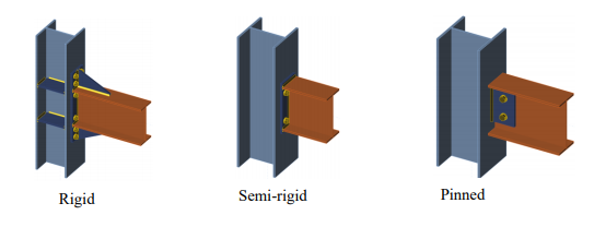
Tornillos, soldaduras y rigidez de una junta
Tanto los tornillos como las soldaduras tienen sus ventajas e inconvenientes. Uno de los aspectos importantes a la hora de elegir una junta es su rigidez prevista. En general, una junta atornillada nunca es tan rígida como una junta soldada. Si elige una unión atornillada, recomendamos calcular la rigidez de dicha unión y tener en cuenta la rigidez resultante en la estructura global. Puede leer cómo es ese cálculo y qué implica aquí, o ver este vídeo.
Únete a 10.000 ingenieros
