
Distribución de fuerzas en los pernos en una unión viga-pilar con placa de extremo
En este artículo, analizamos la distribución de fuerzas en los pernos y los factores que la afectan. Determinar la distribución real de fuerzas en una junta es a menudo imposible. Esto requiere comprender el comportamiento de la junta y conocer las diferentes rigideces y deformaciones. IDEA StatiCa Connection ayuda a comprender estos efectos. Comparamos los resultados de IDEA StatiCa con un cálculo manual para una distribución lineal y mostramos por qué la distribución real de fuerzas es casi siempre no lineal.
Formato
Podríamos analizar infinitas situaciones, pero en este ejemplo nos limitaremos a una unión viga-pilar con placa de extremo con 2x5 pernos M16 8.8 y un momento flector puro en la viga. Las soldaduras se modelan como soldaduras a tope y no se analizarán.
En los siguientes 5 puntos, analizamos cómo diversos factores afectan a la distribución de fuerzas en los pernos.
1 - Centro de rotación libre
Comenzamos con un ejemplo teórico en el que la viga se modela como una placa PL360/40. El momento flector que actúa sobre la viga genera una distribución de tensiones lineal elástica, con el eje neutro exactamente en el centro. Estas tensiones se traducen en una distribución correspondiente de fuerzas en los pernos, pero solo cuando las rigideces son simétricas, los pernos también pueden transmitir fuerzas de compresión y el comportamiento se mantiene completamente elástico.
Para aproximar esto, en la situación 1 modelamos la junta como una placa base infinitamente rígida (E=∞) con anclajes y una holgura. La junta se comporta igual a tracción que a compresión, creando un punto de rotación ideal situado en la fila de pernos central.
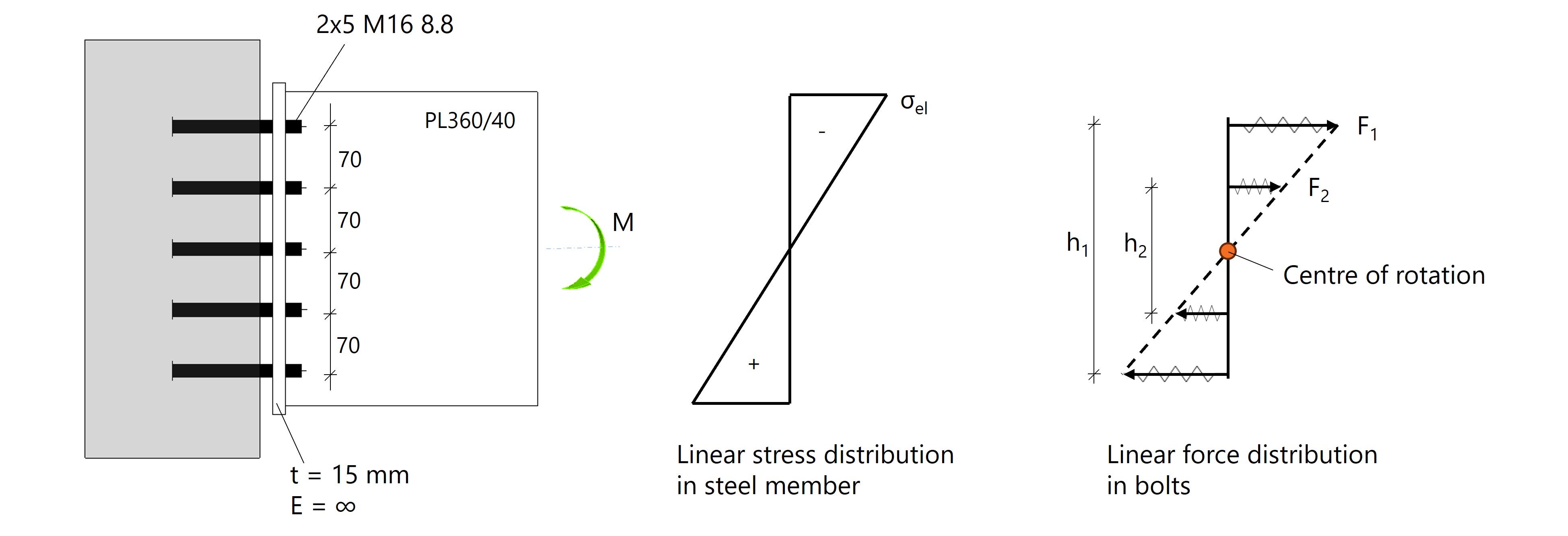
Fig. 1: La distribución de tensiones en la viga es igual a la distribución de fuerzas en los pernos debido a la rotación libre.
Podemos verificar la distribución lineal de fuerzas con un cálculo manual. Si Fi representa la fuerza en un perno, obtenemos el siguiente equilibrio:
\( M = 2F_1 \cdot h_1 + 2F_2 \cdot h_2 \).
Dado que las separaciones entre pernos son iguales, obtenemos:
\( F_2 = \frac{1}{2} \cdot F_1 \).
El momento flector en todos los ejemplos es M = 30 kNm.
Si sustituimos estos valores, podemos calcular F1 y F2:
\( M = 2F_1 \cdot h_1 + F_1 \cdot h_2 = 2F_1 \cdot 0.28 + F_1 \cdot 0.14 = 0.70 F_1 = 30 \) kNm
\( F_1 = 30 / 0.70 = 42.86 \) kN (por perno)
\( F_2 = F_1 / 2 = 42.86 / 2 = 21.43 \) kN (por perno)
Los resultados de F1 y F2 se comparan con las fuerzas en los pernos calculadas en IDEA StatiCa. A continuación vemos que las fuerzas en los pernos son casi iguales.
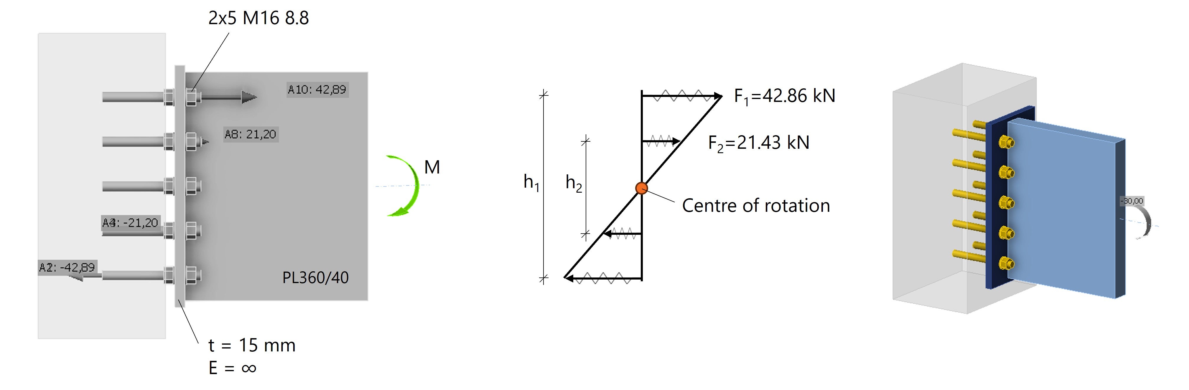
Fig. 2: Distribución lineal de fuerzas en los pernos en IDEA StatiCa modelando los pernos como anclajes.
*Nota: Para comparar el cálculo CBFEM con el cálculo manual, debemos asumir una placa de extremo infinitamente rígida y modelar la viga como una placa PL360/40 en lugar de un perfil en I. Más adelante veremos por qué esto es importante.
2 - Centro de rotación forzado
En una unión con placa de extremo realista, los pernos no transmiten fuerzas de compresión y la compresión se transmite mediante contacto entre la placa de extremo y el ala del pilar. Se produce un cambio en las rigideces que provoca que el centro de rotación, denominado ahora centro de compresión, se desplace hacia abajo.
Con el fin de comparar correctamente los cálculos manuales, hemos modelado una franja estrecha en la parte inferior de la placa de extremo para que el centro de compresión se encuentre siempre en la parte inferior de la placa de extremo.
Además, la viga se modeló como una placa y aumentamos el módulo de elasticidad de las partes de acero para limitar las deformaciones. Esto crea una distribución perfectamente lineal de fuerzas en los pernos con el centro de rotación en la parte inferior de la placa de extremo.
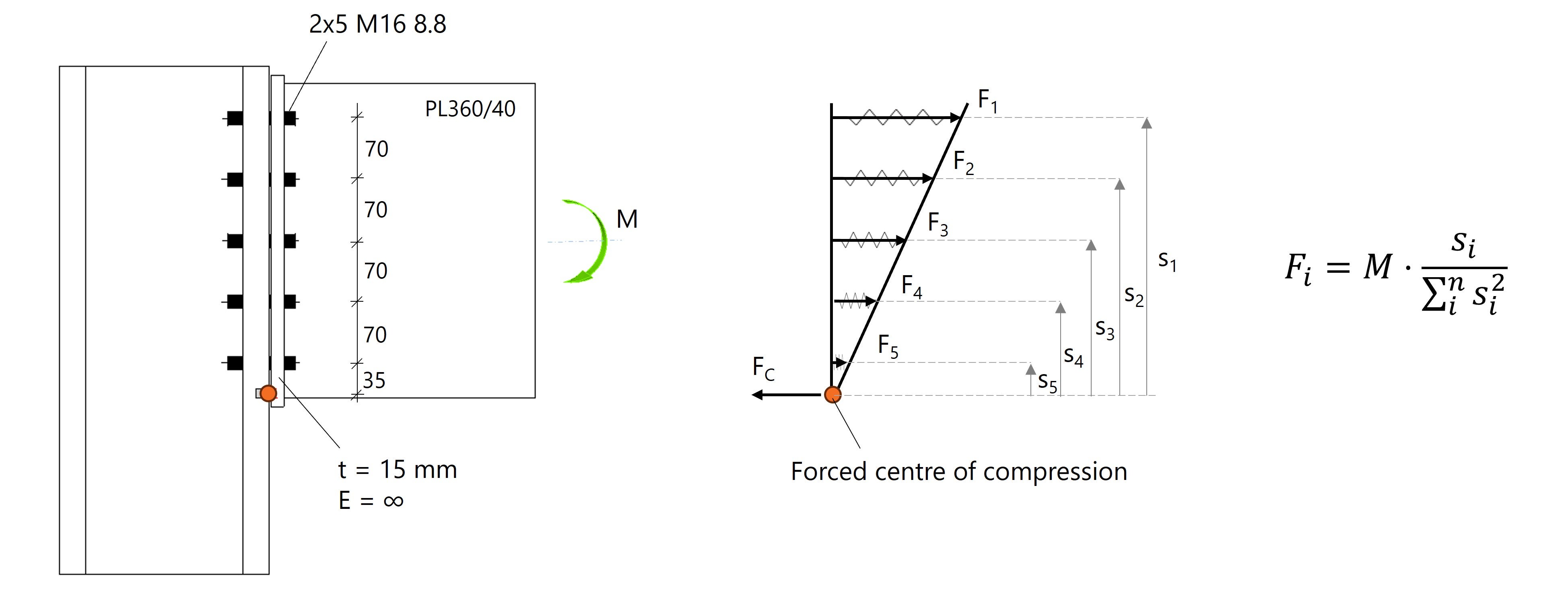
Fig. 3: Distribución lineal de fuerzas en los pernos con el centro de rotación (compresión) en la parte inferior de la placa de extremo.
A partir de las distancias y cargas conocidas, las fuerzas en los pernos se calculan mediante la siguiente ecuación:
\( F_i = M \cdot \frac{s_i}{\sum_{i}^{n} s_i^{2}} \).
Cada fila de pernos tiene 2 pernos y asumimos que las fuerzas son iguales. Para la fila de pernos 1, obtenemos:
\( 2F_1 = M \cdot \frac{s_1}{\sum_{i}^{n} s_i^{2}} = 30 \cdot \frac{0.315}{(0.315^2+0.245^2+0.175^2+0.105^2+0.035^2)} \} = 46.75 \) kN
Esto da \( F_1 = 46.75/2 = 23.37 \) kN
De este modo, podemos calcular la fuerza de un perno por fila:
- \( F_1 = 23.37 \) kN
- \( F_2 = 18.18 \) kN
- \( F_3 = 12.98 \) kN.
- \( F_4 = 7.79 \) kN
- \( F_5 = 2.59 \) kN
Las fuerzas calculadas F1 - F5 coinciden estrechamente con las fuerzas en los pernos en IDEA StatiCa, véase la Fig. 4.
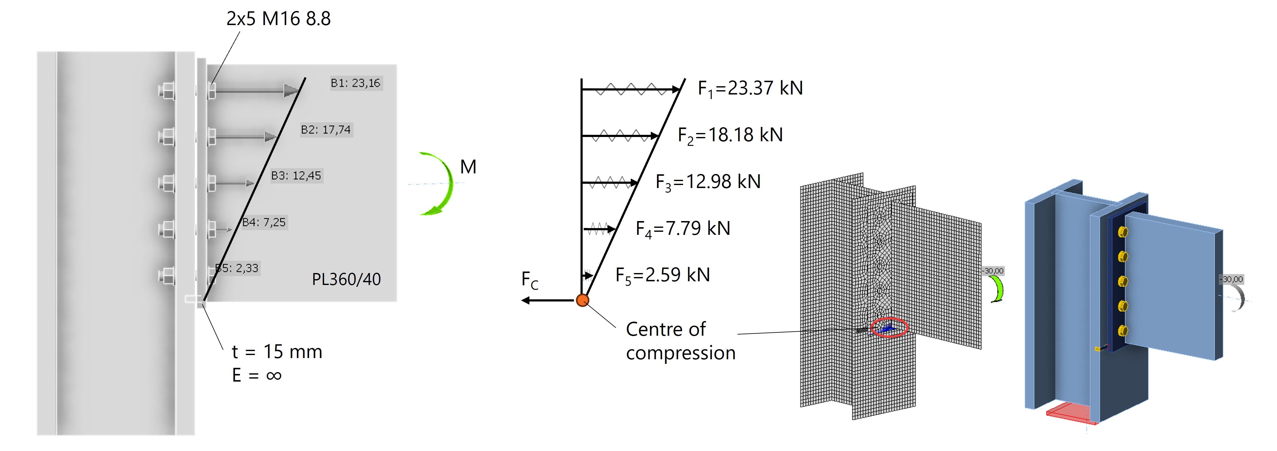
Fig. 4: Distribución lineal de fuerzas en los pernos en IDEA StatiCa con el punto de compresión en la parte inferior de la placa de extremo.
El cálculo manual se compara bien con el cálculo CBFEM en IDEA StatiCa, pero esto solo es posible porque asumimos una placa de extremo irrealmente rígida y un centro de rotación forzado. Modelemos ahora la placa de extremo con el módulo de elasticidad real E=210 GPa.
3 - Placa de extremo flexible
Tomamos el mismo ejemplo que en la situación 2, pero ahora la placa de extremo es de acero S235 con E=210 GPa. La distribución sigue siendo lineal, pero los valores de las fuerzas en los pernos aumentan y ya no son directamente comparables con nuestro cálculo manual. ¿Qué está ocurriendo aquí?
Al analizar cuidadosamente los resultados en IDEA StatiCa, observamos deformaciones en la placa de extremo y se produce efecto de palanca. La fuerza de tracción provoca la flexión de la placa de extremo, generando tensiones de compresión adicionales en los bordes que incrementan las fuerzas en los pernos. Este efecto de palanca es claramente visible en IDEA StatiCa al mostrar las tensiones de contacto entre la placa de extremo y el ala del pilar, véase la Fig. 5.
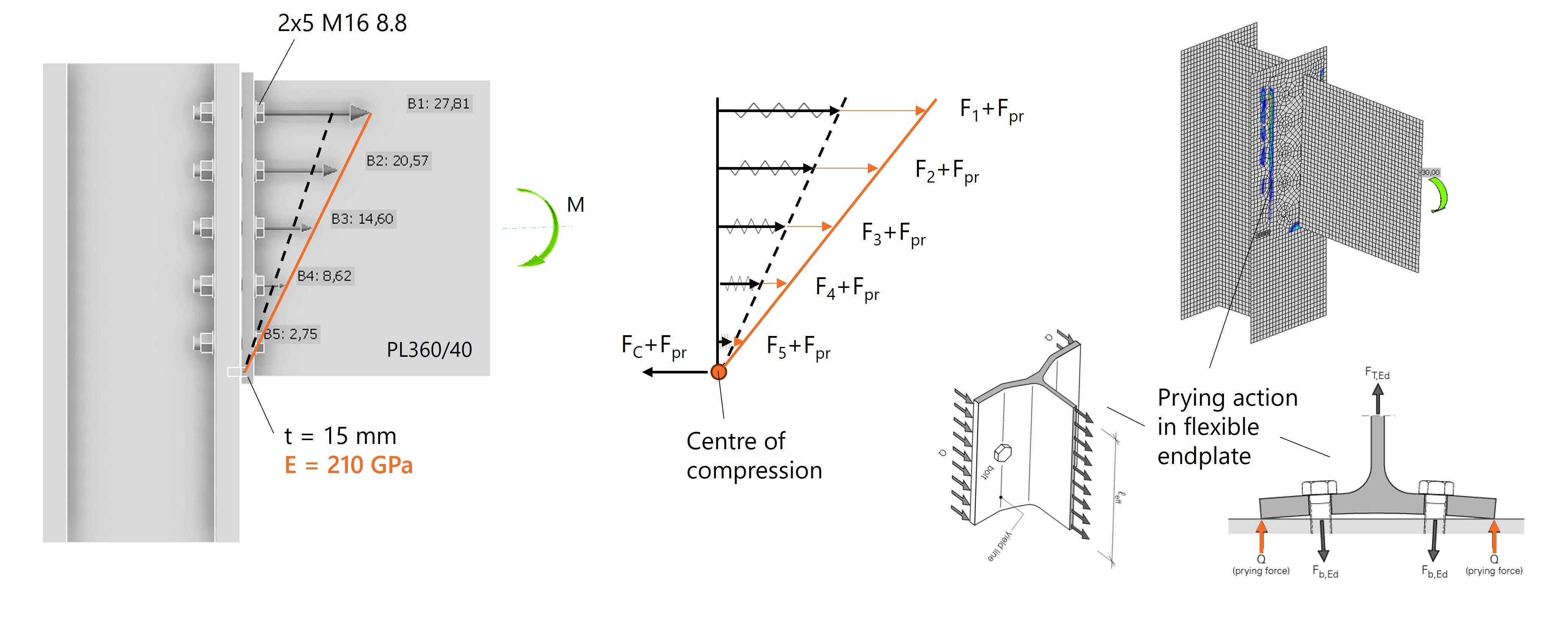
Fig. 5: Las fuerzas en los pernos aumentan como resultado del efecto de palanca (fuerzas de palanca).
En IDEA StatiCa, las fuerzas de palanca se incluyen automáticamente en el cálculo por el Método de los Elementos Finitos y todos los pernos se verifican en consecuencia. El recálculo manual es posible, pero requiere más tiempo.
Hasta ahora, hemos modelado la viga como una placa PL360/40, con el fin de analizar una distribución de fuerzas lo más predecible posible. Pero, ¿qué ocurre si la viga es un IPE360?
4 - ¿Qué ocurre si la viga es un perfil en I?
Si modelamos la viga como un perfil en I, lo cual es más habitual en la práctica, la rigidez relativa en la unión cambia. La presencia de un ala superior aumenta la rigidez en torno a la fila de pernos superior. ¿Y qué ocurre cuando aumenta la rigidez? Las partes más rígidas absorben más fuerza, incrementando las fuerzas en los pernos de la fila superior.
El resultado es una distribución no lineal de fuerzas en los pernos, como se muestra en la Fig. 6.
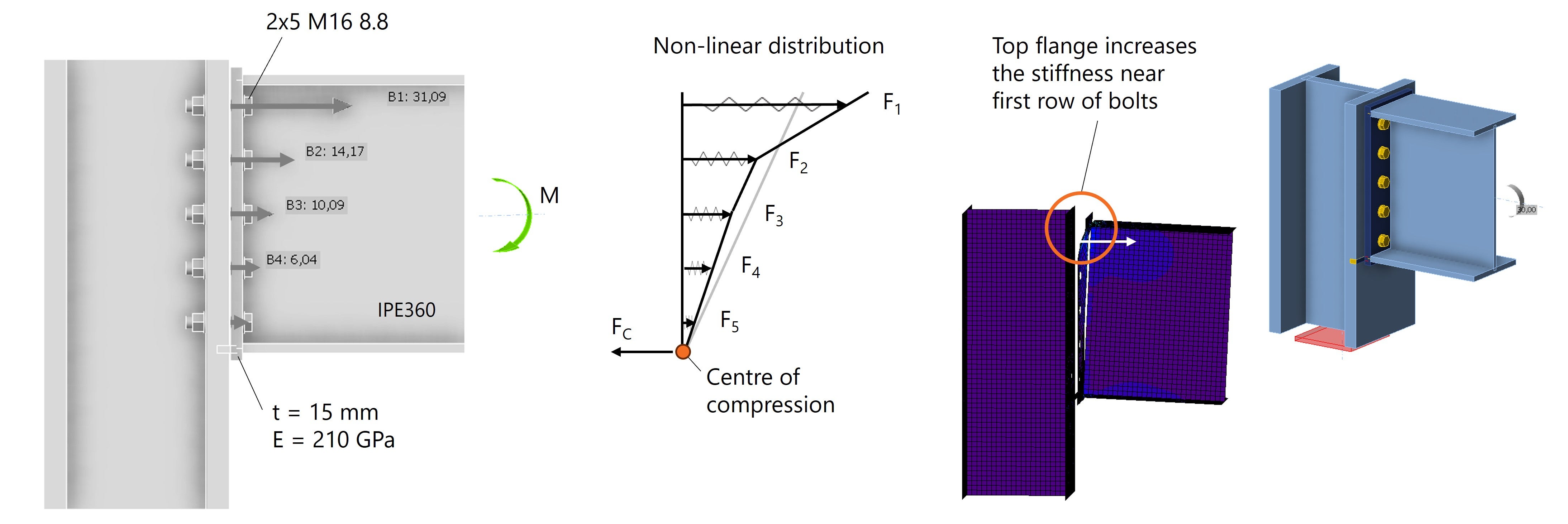
Fig. 6: Distribución no lineal de fuerzas en los pernos debido a un cambio en las relaciones de rigidez.
Al distribuir fuerzas en una junta, deben considerarse las relaciones de rigidez dentro de la junta. Esta es la parte más difícil del proceso de cálculo, ya que muchos factores pueden influir en ella. Considérese, por ejemplo:
- Espesor de la placa de extremo
- Tipo de sección transversal
- Rigidizadores
- Disposición de los pernos
- Propiedades del material
- Comportamiento elástico o plástico
Al analizar los resultados en IDEA StatiCa, obtenemos información sobre la distribución de fuerzas y podemos optimizar nuestro diseño si es necesario.
5 - Colocar los pernos donde más contribuyen
Por último, se muestra cómo se puede influir en la distribución de fuerzas desplazando los pernos, con el objetivo de crear el diseño más eficiente posible.
Si asumimos que solo está presente un momento flector hacia abajo, la ubicación más eficiente para los pernos es cerca del ala superior. Esta ubicación es la más alejada del centro de rotación y se encuentra en la parte más rígida, cerca de las alas. Al extender la placa de extremo y desplazar la fila de pernos 4 por encima del ala superior, las fuerzas se reducen y se distribuyen mejor entre los pernos de las dos filas superiores, véase la Fig. 7.
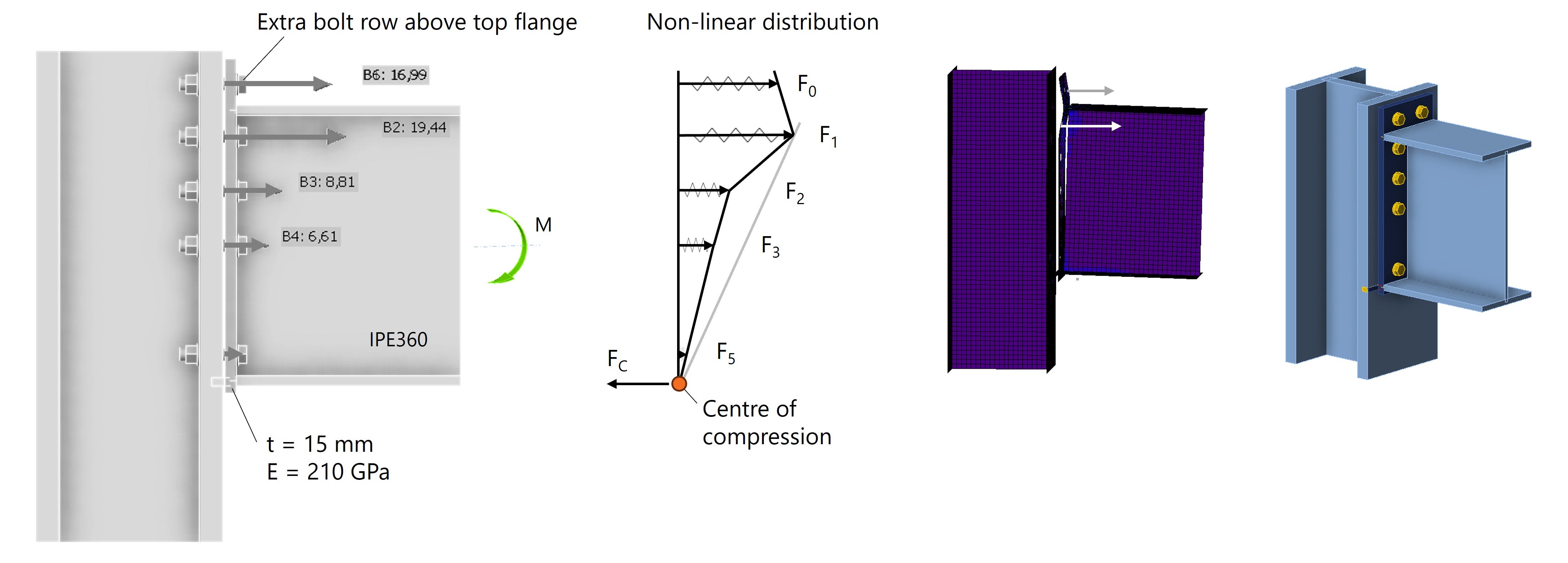
Fig. 7: Los pernos cerca del ala superior absorben la mayor parte de la fuerza.
La sección por encima del ala superior es menos rígida que la que se encuentra por debajo del ala superior, por lo que los pernos de la fila 0 absorben una fuerza ligeramente menor. Podríamos optimizar esto aún más añadiendo un rigidizador en la parte superior, véase la Fig. 8.
Conclusión
La distribución de fuerzas en los pernos de una placa de extremo nunca es perfectamente lineal en la práctica. Las variaciones en rigidez, deformación y efectos de palanca dan lugar a un patrón de fuerzas complejo, lo que significa que los cálculos manuales solo pueden proporcionar una aproximación aproximada.
Con IDEA StatiCa, podemos analizar el comportamiento real de la unión. El software muestra cómo se distribuyen las fuerzas y cómo factores como el espesor de la placa, el tipo de sección, la rigidez del material y la disposición de los pernos influyen en los resultados. Esta información permite a los ingenieros ir más allá de las verificaciones normativas básicas y optimizar verdaderamente sus diseños, por ejemplo, reposicionando los pernos o añadiendo rigidizadores donde sea necesario.
Observación final
Este estudio se ha limitado a una unión viga-pilar con placa de extremo sometida a momento flector. Cabe imaginar que la distribución de fuerzas en los pernos se vuelve aún más compleja cuando también se aplica un esfuerzo cortante o una fuerza normal, se utilizan otras secciones transversales de perfil, se añaden rigidizadores, etc. Todos estos factores afectan a la distribución de fuerzas al modificar la rigidez de los distintos componentes.
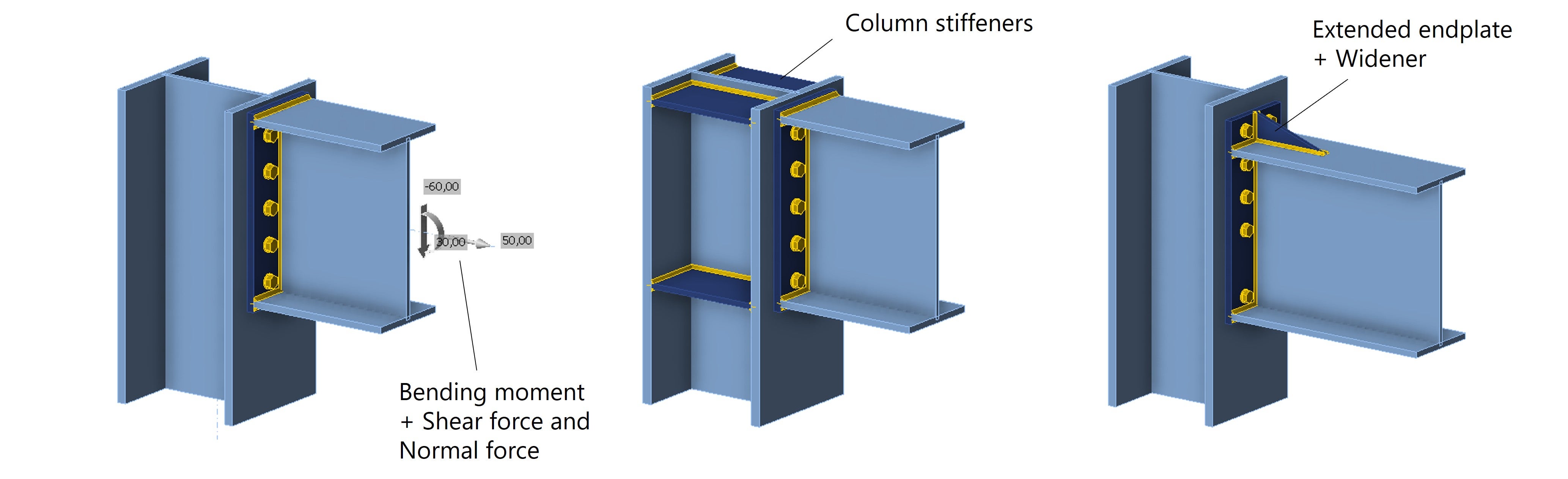
Fig. 8: Unión con placa de extremo con otras fuerzas internas - rigidizadores de pilar - placa de extremo extendida con rigidizador.
Prueba IDEA StatiCa gratis
