Únava – Koutové svary průřezu I
Popis
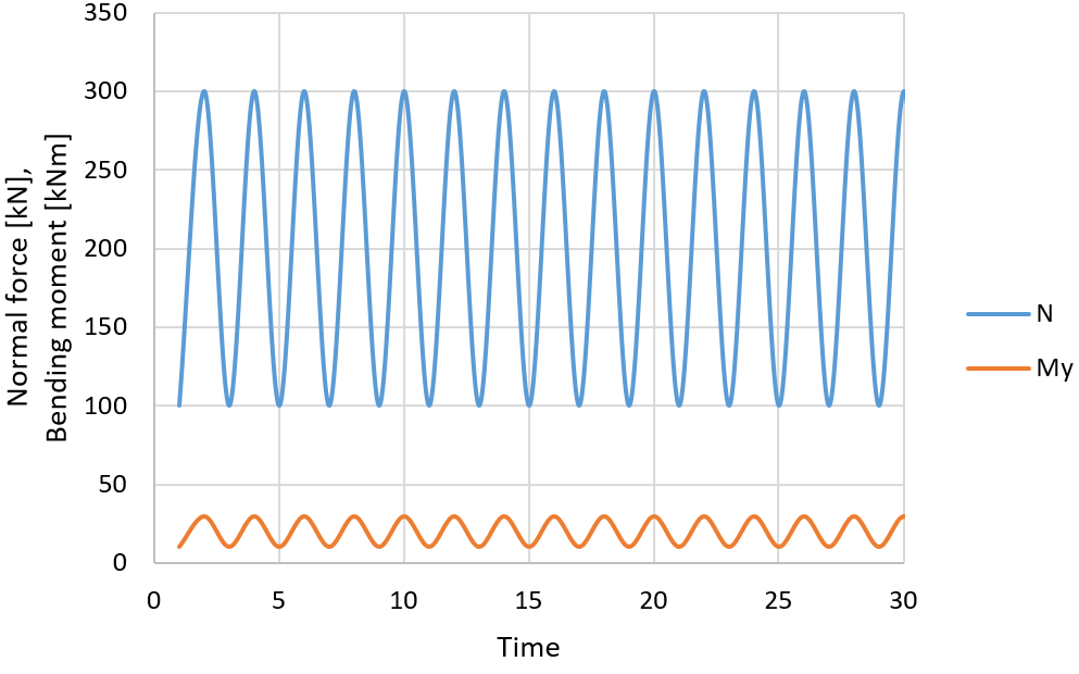
Dva nosníky průřezu IPE 200 z oceli třídy S355 jsou vzájemně svařeny příčnými plně provařenými tupými svary. Nosníky v místě zkoumaného detailu jsou zatíženy ohybovým momentem a normálovým napětím:
| Normálová síla N [kN] | Ohybový moment My [kNm] | |
| Minimum | 100 | 10 |
| Maximum | 300 | 30 |
Stanovení nominálního napětí
Součinitel spolehlivosti \(\gamma_{Mf}\) je vybrán z Tabulky 3.1 (EN 1993-1-9). Pro tento příklad předpokládejme \(\gamma_{Mf} = 1.15\).
| Metoda posouzení | Důsledek poruchy | |
| Nízký důsledek | Vysoký důsledek | |
| Tolerantní k poškození | 1 | 1.15 |
| Bezpečná životnost | 1.15 | 1.35 |
Analytická metoda
Nominální napětí je stanoveno jednoduchým vzorcem:
\[\sigma = \frac{N}{A} + \frac{M_y}{W_y} \]
Pro minimální normálové napětí platí:
\[\sigma_{min} = \frac{100 \cdot 10^3}{2850} + \frac{10 \cdot 10^6}{194000} = 86.6 \, \textrm{MPa}\]
Pro maximální normálové napětí platí:
\[\sigma_{max} = \frac{300 \cdot 10^3}{2850} + \frac{30 \cdot 10^6}{194000} = 259.9 \, \textrm{MPa}\]
Rozkmit napětí je:
\[\sigma_{max} - \sigma_{min} = 259.9 - 86.6 = 173.3 \, \textrm{MPa} \]
Smykové napětí není přítomno. Součinitel koncentrace napětí kf je vybrán pro příslušný detail. Pro plně provařené tupé svary přes celý průřez zatížené normálovou silou je součinitel koncentrace napětí kf = 1,0.
\[\Delta \sigma_R = \gamma_{Mf} \cdot k_f \cdot (\sigma_{max} - \sigma_{min}) = 1.15 \cdot 1.0 \cdot 173.3 = 199.3\,\textrm{MPa} \]
Analýza CBFEM
Zatížení je nastaveno takto:
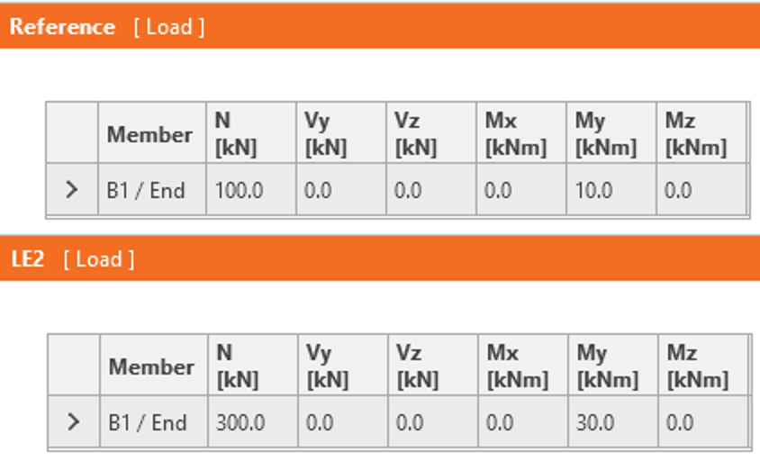
Referenční zatížení je minimální zatížení a LE2 je maximální zatížení.
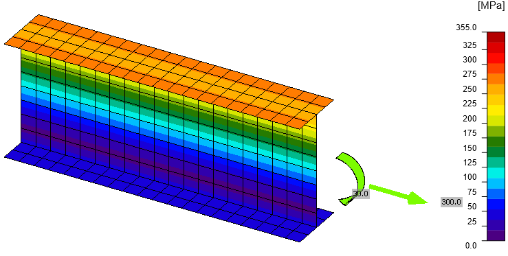
Napětí von Mises při maximálním zatížení (LE2) ukazuje, že žádná část nepřekračuje mez kluzu.
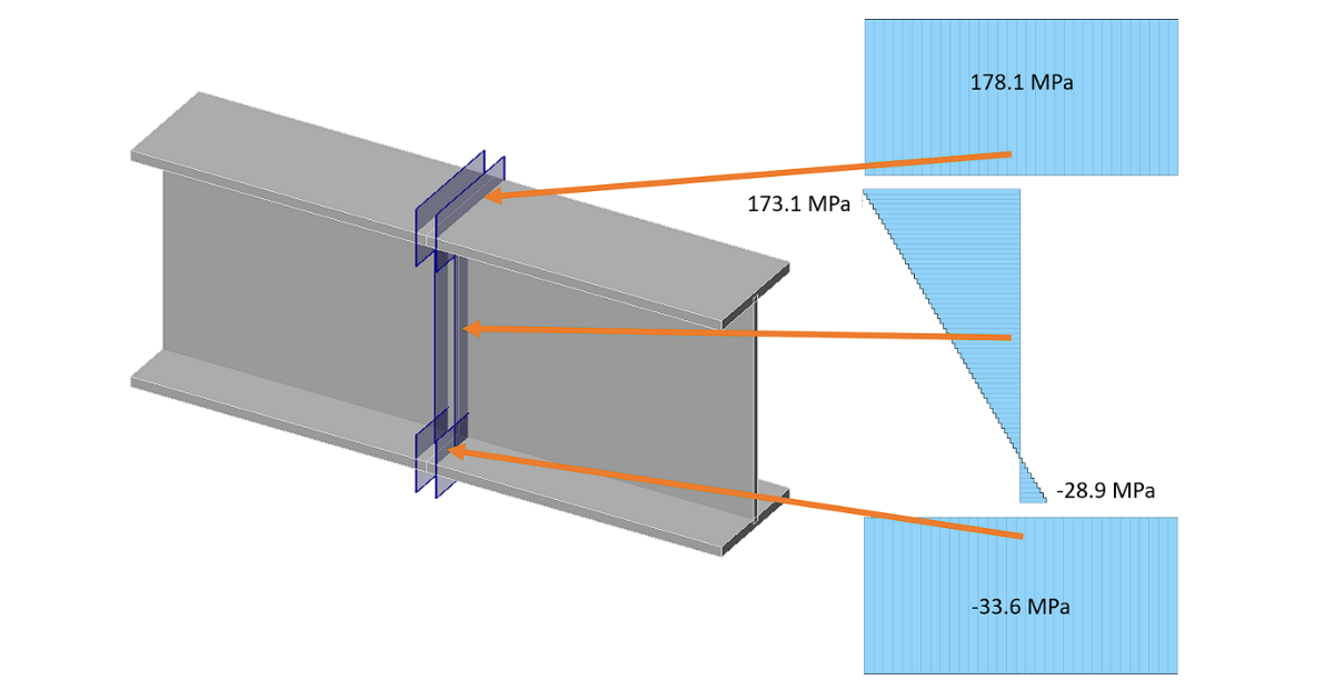
Roviny jsou automaticky generovány v blízkosti tupých svarů a napětí jsou zobrazena v tabulce posouzení:
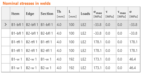

Součinitel koncentrace napětí kf je převzat z metody konečných prvků a není nutné jej znovu aplikovat. Součinitel spolehlivosti musí být použit.
\[\Delta \sigma_R = \gamma_{Mf} \cdot \sigma_{max} = 1.15 \cdot 178.1 = 204.8\,\textrm{MPa} \]
Porovnání
IDEA StatiCa vykazuje mírně vyšší normálové napětí (178,1 MPa) než analytický přístup (173,3 MPa). Jediný rozdíl je způsoben předpokládaným průřezem v IDEA StatiCa s mírně odlišnými průřezovými charakteristikami:
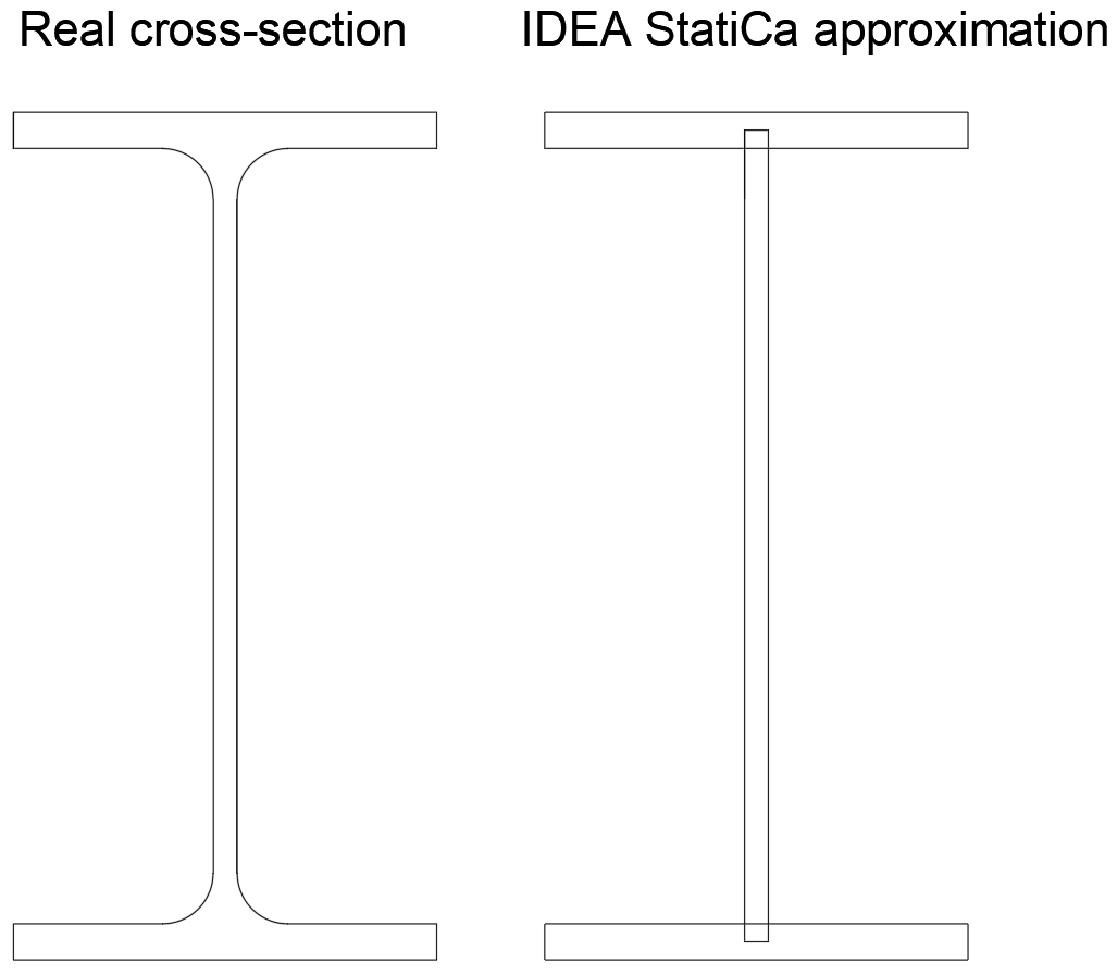
| Skutečný | IDEA StatiCa | |
| A | 2850 mm2 | 2772 mm2 |
| Wy | 194 000 mm3 | 188 732 mm3 |
Při použití průřezových charakteristik zjednodušeného průřezu jsou získány stejné výsledky jako v IDEA StatiCa: \(\sigma_{min} = 89.1\,\textrm{MPa}\), \(\sigma_{max} = 267.2\,\textrm{MPa}\), \(\sigma_{max} - \sigma_{min} = 178.1\,\textrm{MPa}\).
Analýza únavy
Příklad analýzy únavy pomocí nominálního napětí je uveden pro návrh podle EN 1993-1-9:2005.
Kategorie detailu 90 je vybrána z Tabulky 8.3.
Pro konstantní amplitudy rozkmitů nominálního napětí je počet cyklů pro únavovou životnost převzat z Kapitoly 7.1:
\[N_R = \frac{\Delta \sigma_c^m \cdot 2\cdot 10^6}{\Delta \sigma_R^m}\]
Ruční výpočet:
\[N_R = \frac{90^3 \cdot 2\cdot 10^6}{199.3^3} = 184\,177\, \textrm{cycles}\]
IDEA Connection:
\[N_R = \frac{90^3 \cdot 2\cdot 10^6}{204.8^3} = 169\,734 \, \textrm{cycles}\]
Počet cyklů, které může styčník vydržet, je v IDEA Connection mírně nižší z důvodu zjednodušení průřezu.
Referenční příklad
Vstupy
Prvky: B1, B2 - IPE200
Třída oceli: S 355
Účinky zatížení:
- Referenční: N = 100 kN, My = 10 kNm
- LE2: N = 300 kN, My = 30 kNm
Výrobní operace: Řez šikmým řezem, tupé svary
Výstupy
Maximální rozkmit normálového napětí: 178,1 MPa v horní pásnici
Rozkmit smykového napětí: 0 MPa