使用 CSFM 对结构进行评估时,需分别针对正常使用极限状态和承载能力极限状态荷载组合进行两种不同的分析。正常使用极限状态分析假定构件的极限性能是令人满意的,且材料在正常使用荷载水平下不会达到屈服条件。这一方法使得正常使用极限状态分析可以采用简化的本构模型(混凝土应力-应变图采用线性段),从而提高数值稳定性和计算速度。因此,建议采用下文所述的工作流程,即首先进行承载能力极限状态分析。
这样的模型可以非常快速地完成计算,使设计人员能够高效地检查结构构件的配筋细部,并反复重新运行分析,直至满足最不利荷载组合下的所有验算要求。一旦此初步分析的所有验算要求均得到满足,建议纳入完整的极限荷载组合,并采用较细的网格尺寸(即程序推荐的网格尺寸)。用户可以通过倍数来调整网格尺寸,该倍数可在 0.5 到 5 之间取值(图 19)。
基本结果和验算结果(应力、应变和承载比,即根据规范计算得到的“计算值/限值”,以及混凝土构件中主应力的方向)通过不同的图形显示,其中压力通常以红色表示,拉力以蓝色表示。既可以突出显示整个结构的全局最小值和最大值,也可以显示每个用户自定义部分的最小值和最大值。在程序的另一个选项卡中,可以显示更多高级结果,如张量值、结构变形,以及用于计算钢筋拉力刚化所采用的配筋率(有效配筋率和几何配筋率)。此外,还可以显示所选荷载组合或荷载工况下的荷载和反力。
正常使用极限状态分析对承载能力极限状态分析所采用的本构模型进行了一定的简化。分析中假定为完全粘结,即在正常使用极限状态下不对锚固长度进行验算。此外,忽略混凝土受压应力-应变曲线的塑性段,其弹性段则为线性且无限延伸。这些简化提高了数值稳定性和计算速度,并且只要正常使用状态下材料的实际应力限值明显低于其屈服点(这也是规范所要求的),就不会降低解答的普遍适用性。因此,仅当所有验算要求均得到满足时,用于正常使用极限状态的简化模型才是有效的。
裂缝宽度计算 裂缝宽度的计算有两种方式——稳定裂缝和非稳定裂缝。根据结构各部分的几何配筋率来决定采用哪种裂缝计算模型(稳定裂缝采用 TCM 模型,非稳定裂缝采用 POM 模型)。
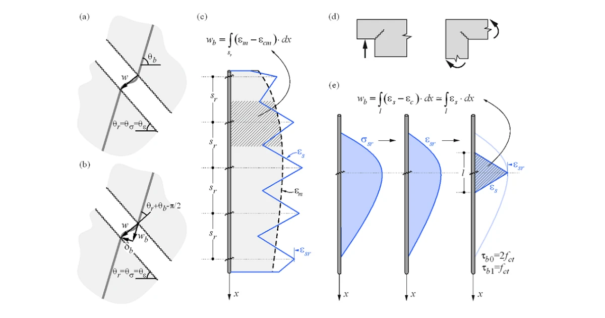
Fig. 20 Crack width calculation: (a) considered crack kinematics; (b) projection of crack kinematics into the principal \textsf{\textit{\footnotesize{Fig. 20 \qquad Crack width calculation: (a) considered crack kinematics; (b) projection of crack kinematics into the principal}}} Fig. 20 Crack width calculation: (a) considered crack kinematics; (b) projection of crack kinematics into the principal directions of the reinforcing bar; (c) crack width in the direction of the reinforcing bar for stabilized cracking; (d) cases with \textsf{\textit{\footnotesize{directions of the reinforcing bar; (c) crack width in the direction of the reinforcing bar for stabilized cracking; (d) cases with}}} directions of the reinforcing bar; (c) crack width in the direction of the reinforcing bar for stabilized cracking; (d) cases with local non-stabilized cracking regardless of the reinforcement amount; (e) crack width in the direction of the reinforcing bar \textsf{\textit{\footnotesize{local non-stabilized cracking regardless of the reinforcement amount; (e) crack width in the direction of the reinforcing bar}}} local non-stabilized cracking regardless of the reinforcement amount; (e) crack width in the direction of the reinforcing bar for non-stabilized cracking. \textsf{\textit{\footnotesize{for non-stabilized cracking.}}} for non-stabilized cracking.
CSFM(协调应力场法)对大多数验证项目(如构件承载力、挠度等)可直接给出结果,而裂缝宽度结果则按照图 20 所述方法,由有限单元法分析直接提供的钢筋应变结果计算得出。模型采用无滑移的裂缝运动学(纯裂缝张开)(图 20a),这与模型的主要假设一致。应力和应变的主方向决定了裂缝的倾角(θr s = θe )。根据图 20b,裂缝宽度(w )可投影到钢筋方向(wb ),得到:
w = w b cos ( θ r + θ b − π 2 ) w = \frac{w_b}{\cos\left(θ_r + θ_b - \frac{π}{2}\right)} w = cos ( θ r + θ b − 2 π ) w b
其中 θb
请注意,程序显示的 θr b π/2 。这意味着上述公式适用于钢筋与裂缝分别穿过笛卡尔坐标系不同象限的情况,如图 20 所示,钢筋穿过第 I、III 象限,裂缝穿过第 II、IV 象限。对于钢筋与裂缝穿过相同象限的情况,公式需修改如下:
w = w b cos ( − θ r + θ b + π 2 ) w = \frac{w_b}{\cos\left(-θ_r + θ_b + \frac{π}{2}\right)} w = cos ( − θ r + θ b + 2 π ) w b
分量 wb 基于拉力刚化模型,通过对钢筋应变积分一致计算得出。对于裂缝形态已充分发展的区域,沿钢筋计算的平均应变(em sr )积分,如图 20c 所示。虽然这种计算裂缝方向的方法与裂缝实际位置不完全对应,但仍能提供具有代表性的数值,所得裂缝宽度结果可与规范要求的钢筋位置处裂缝宽度限值进行比较。
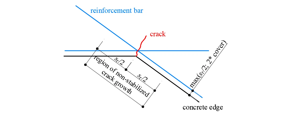
在计算结构的凹角处会出现特殊情况。此时,凹角预先确定了单条裂缝的位置,在相邻裂缝进一步发展之前,该裂缝呈非稳定状态。这些相邻裂缝通常在正常使用范围之后才会发展(Mata-Falcón 2015),因此将该区域的裂缝宽度按非稳定裂缝计算是合理的(图 21)。
Fig. 21 Definition of the region at concave corners in which the crack width is computed as if it were non-stabilized. \textsf{\textit{\footnotesize{Fig. 21\qquad Definition of the region at concave corners in which the crack width is computed as if it were non-stabilized.}}} Fig. 21 Definition of the region at concave corners in which the crack width is computed as if it were non-stabilized.
拉力刚化 拉力刚化的实现区分了稳定裂缝形态和非稳定裂缝形态两种情况。在两种情况下,默认均假设混凝土在加载前已完全开裂。
Fig. 22 Tension stiffening model: (a) tension chord element for stabilized cracking with distribution of bond shear, \textsf{\textit{\footnotesize{Fig. 22\qquad Tension stiffening model: (a) tension chord element for stabilized cracking with distribution of bond shear,}}} Fig. 22 Tension stiffening model: (a) tension chord element for stabilized cracking with distribution of bond shear, steel and concrete stresses, and steel strains between cracks, considering average crack spacing); (b) pull-out assumption \textsf{\textit{\footnotesize{steel and concrete stresses, and steel strains between cracks, considering average crack spacing); (b) pull-out assumption}}} steel and concrete stresses, and steel strains between cracks, considering average crack spacing); (b) pull-out assumption for non-stabilized cracking with distribution of bond shear and steel stresses and strains around the crack; (c) resulting \textsf{\textit{\footnotesize{for non-stabilized cracking with distribution of bond shear and steel stresses and strains around the crack; (c) resulting}}} for non-stabilized cracking with distribution of bond shear and steel stresses and strains around the crack; (c) resulting tension chord behavior in terms of reinforcement stresses at the cracks and average strains for European B500B steel; \textsf{\textit{\footnotesize{tension chord behavior in terms of reinforcement stresses at the cracks and average strains for European B500B steel;}}} tension chord behavior in terms of reinforcement stresses at the cracks and average strains for European B500B steel; (d) detail of the initial branches of the tension chord response. \textsf{\textit{\footnotesize{(d) detail of the initial branches of the tension chord response.}}} (d) detail of the initial branches of the tension chord response.
稳定裂缝
对于充分发展的裂缝形态,拉力刚化采用拉力弦模型(TCM)(Marti et al. 1998;Alvarez 1998)引入——图 22a——该模型已被证明尽管简单,却能给出优异的响应预测(Burns 2012)。TCM 假设粘结剪应力-滑移关系为阶梯形刚性完全塑性,当 σs fy 时 τb b 0fctm ,当 σs fy 时 τb b 1fctm 。将每根钢筋视为拉力弦——图 22b 和图 22a——对于任意给定的裂缝处最大钢筋应力(或应变)值,可确定两条裂缝之间的粘结剪力、钢筋和混凝土应力分布以及应变分布。
当 sr = sr 0 时,由于两裂缝中间处 σc 1fct ,新裂缝可能形成也可能不形成。因此,裂缝间距可能相差两倍,即 sr = λsr 0 ,其中 λ = 0.5…1.0。假定 λ 的某一值,弦的平均应变(εm sr
ε m = σ s r E s − τ b 0 s r E s Ø \varepsilon_m = \frac{\sigma_{sr}}{E_s} - \frac{\tau_{b0}s_r}{E_s Ø} ε m = E s σ sr − E s Ø τ b 0 s r
for σ s r ≤ f y \textrm{for}\qquad\qquad\sigma_{sr} \le f_y for σ sr ≤ f y
ε m = ( σ s r − f y ) 2 Ø 4 E s h τ b 1 s r ( 1 − E s h τ b 0 E s τ b 1 ) + ( σ s r − f y ) E s τ b 0 τ b 1 + ( ε y − τ b 0 s r E s Ø ) {\varepsilon_m} = \frac{{{{\left( {{\sigma_{sr}} - {f_y}} \right)}^2}Ø}}{{4{E_{sh}}{\tau _{b1}}{s_r}}}\left( {1 - \frac{{{E_{sh}}{\tau_{b0}}}}{{{E_s}{\tau_{b1}}}}} \right) + \frac{{\left( {{\sigma_{sr}} - {f_y}} \right)}}{{{E_s}}}\frac{{{\tau_{b0}}}}{{{\tau_{b1}}}} + \left( {{\varepsilon_y} - \frac{{{\tau_{b0}}{s_r}}}{{{E_s}Ø}}} \right) ε m = 4 E s h τ b 1 s r ( σ sr − f y ) 2 Ø ( 1 − E s τ b 1 E s h τ b 0 ) + E s ( σ sr − f y ) τ b 1 τ b 0 + ( ε y − E s Ø τ b 0 s r )
for f y ≤ σ s r ≤ ( f y + 2 τ b 1 s r Ø ) \textrm{for}\qquad\qquad{f_y} \le {\sigma _{sr}} \le \left( {{f_y} + \frac{{2{\tau _{b1}}{s_r}}}{Ø}} \right) for f y ≤ σ sr ≤ ( f y + Ø 2 τ b 1 s r )
ε m = f s E s + σ s r − f y E s h − τ b 1 s r E s h Ø \varepsilon_m = \frac{f_s}{E_s} + \frac{\sigma_{sr}-f_y}{E_{sh}} - \frac{\tau_{b1} s_r}{E_{sh} Ø} ε m = E s f s + E s h σ sr − f y − E s h Ø τ b 1 s r
for ( f y + 2 τ b 1 s r Ø ) ≤ σ s r ≤ f t \textrm{for}\qquad\qquad\left(f_y + \frac{2\tau_{b1}s_r}{Ø}\right) \le \sigma_{sr} \le f_t for ( f y + Ø 2 τ b 1 s r ) ≤ σ sr ≤ f t
其中:Esh 钢材硬化模量 Esh = (ft – fy )/(εu fy /Es ) ,
Es 钢筋弹性模量,
Ø 钢筋直径,
sr
σsr
σs
fy 钢筋屈服强度。
IDEA StatiCa Detail 中 CSFM(协调应力场法)的实现在进行计算机辅助应力场分析时,默认采用平均裂缝间距。平均裂缝间距取最大裂缝间距的 2/3(λ = 0.67),这遵循了基于弯曲和拉伸试验所提出的建议(Broms 1965;Beeby 1979;Meier 1983)。需要注意的是,裂缝宽度计算采用最大裂缝间距(λ = 1.0),以获得偏于保守的结果。
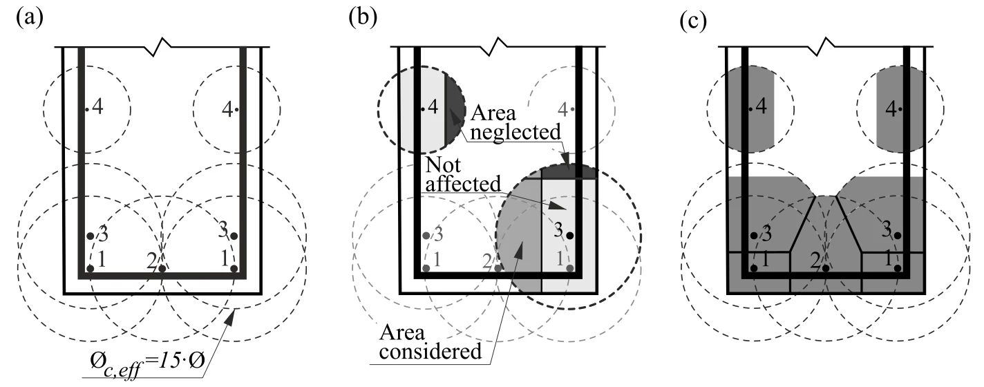
TCM 的应用取决于配筋率,因此为每根钢筋合理分配裂缝间受拉混凝土面积至关重要。已开发了一套自动数值程序,用于确定相应的有效配筋率(ρeff = As /Ac,eff
Fig. 23 Effective area of concrete in tension for stabilized cracking: (a) maximum concrete area that can be activated; \textsf{\textit{\footnotesize{Fig. 23\qquad Effective area of concrete in tension for stabilized cracking: (a) maximum concrete area that can be activated;}}} Fig. 23 Effective area of concrete in tension for stabilized cracking: (a) maximum concrete area that can be activated; (b) cover and global symmetry condition; (c) resultant effective area. \textsf{\textit{\footnotesize{(b) cover and global symmetry condition; (c) resultant effective area.}}} (b) cover and global symmetry condition; (c) resultant effective area.
非稳定裂缝
几何配筋率低于 ρcr
ρ c r = f c t f y − ( n − 1 ) f c t {\rho _{cr}} = \frac{{{f_{ct}}}}{{{f_y} - \left( {n - 1} \right){f_{ct}}}} ρ cr = f y − ( n − 1 ) f c t f c t
其中:
fy 钢筋屈服强度,
fct 混凝土抗拉强度,
n 弹性模量比,n = Es / Ec 。
对于普通混凝土和钢筋,ρcr
对于配筋率低于 ρcr sr s m ft )时零滑移点之间的距离计算(图 22b 中的 l ε,avg ),得到如下关系式:
所提出的模型可计算有粘结钢筋的行为,该行为最终在分析中加以考虑。图 22c-d 示出了最常用的欧洲钢筋(B500B,ft / fy = 1.08,εu