Afschuiving in RCS - cirkelvormige doorsneden
Laten we beginnen met het herhalen van de richtingen van de afschuifspanningen in een cirkelvormige doorsnede.
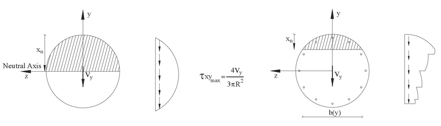
Afschuifspanningen voor een ongescheurde massieve cirkelvormige doorsnede hebben een verticale richting en worden verondersteld constant te zijn over de breedte b. Als er buigscheuren optreden in de doorsnede, wordt de verticale verdeling van de afschuifspanning gewijzigd. Een schets van dergelijke afschuifspanningsverdelingen is te vinden in de volgende figuur.
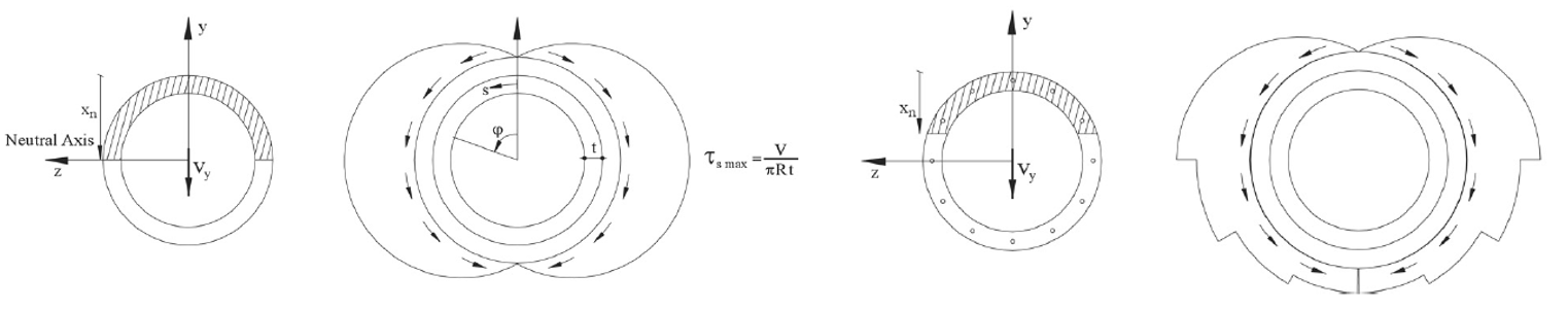
Voor het bepalen van afschuifspanningen in gesloten dunwandige staven wordt aangenomen dat de afschuifspanningen gelijkmatig verdeeld zijn over de volledige dikte t van de wand en evenwijdig aan de doorsnederanden werken.
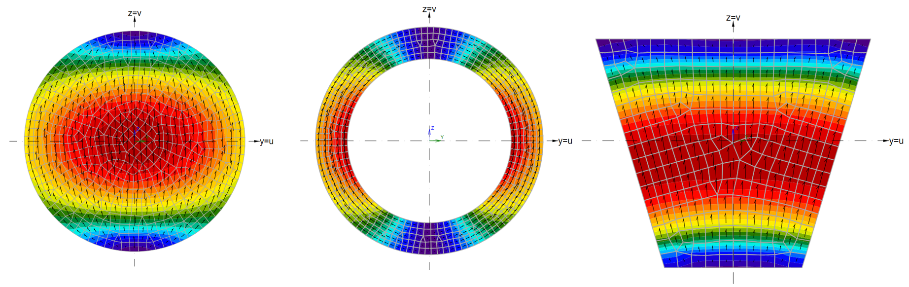
Deze aannames kunnen worden geverifieerd door middel van een EEM-analyse van de doorsneden. In de volgende figuur zijn de resultaten van de EEM-analyse te zien voor drie typen doorsneden: massieve cirkelvormige doorsnede, holle cirkelvormige doorsnede en trapeziumvormige doorsnede. De berekeningen zijn uitgevoerd in de Algemene doorsnede-editor tool. Afschuifspanningen veroorzaakt door eenheidsdwarskracht Vv worden weergegeven inclusief pijlen van de spanningsstroom.
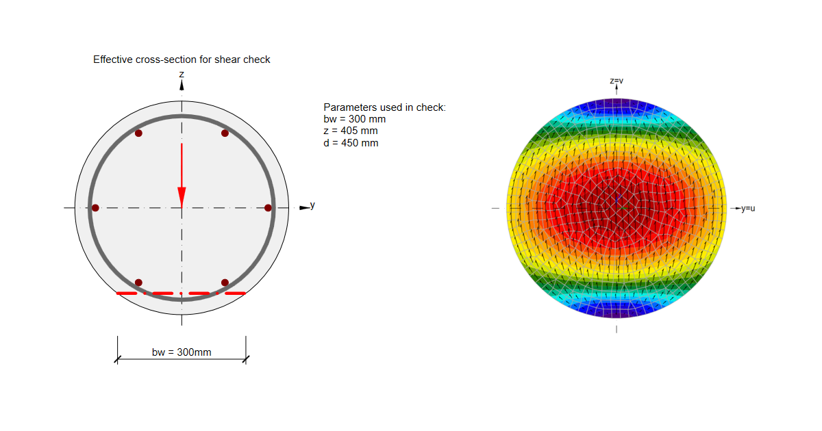
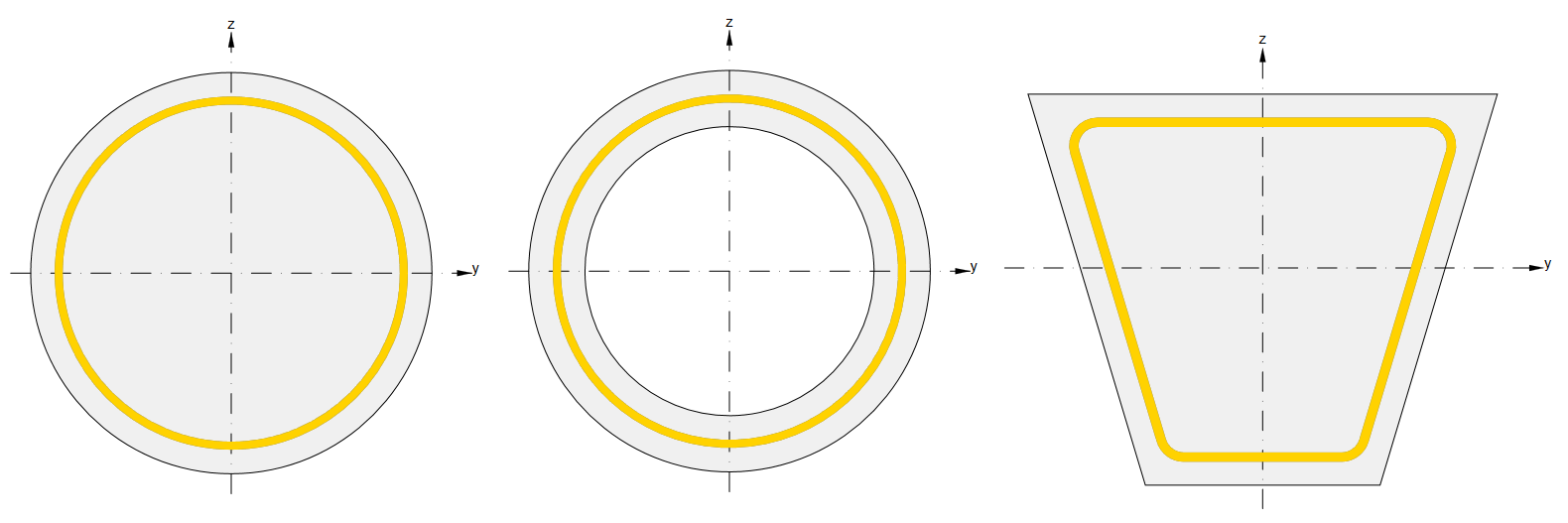
Laten we beugels op gelijke afstand van de doorsnederanden beschouwen, zoals weergegeven in de onderstaande figuur.
We kunnen opmerken dat de afschuifspanningsstroom in de massieve cirkelvormige doorsnede niet de beugel geometrie volgt, wat leidt tot een verminderde effectiviteit van de afschuivingswapening. Dit effect wordt in rekening gebracht door de reductiefactor χ, die de afschuifweerstand VRd,s beïnvloedt.
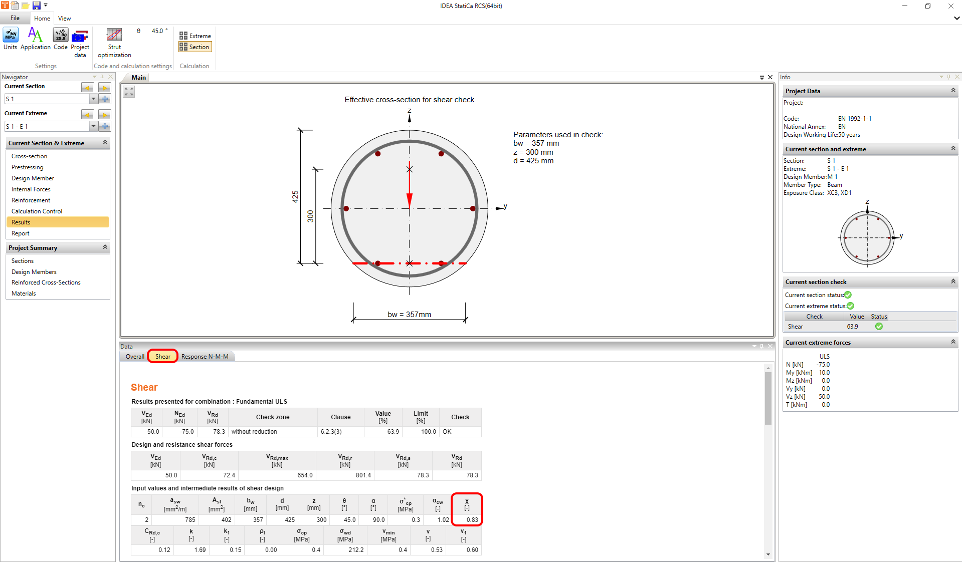
In IDEA StatiCa RCS wordt de reductiefactor berekend volgens de volgende formule.
\[{χ}={{b}_{w}} / {{d}_{h}}\le 0.85\]
Waarbij bw de afschuifbreedte is en dh de diameter van de cirkelvormige beugel.
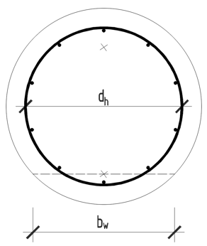
De afschuifbreedte bw wordt op verschillende manieren berekend.
1. Methode
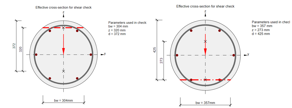
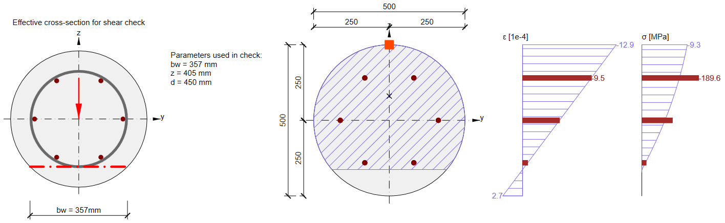
De afschuifbreedte bw wordt berekend als de minimale breedte tussen de trek- en drukkoord bij het optreden van buigscheuren in de UGT. Dit is te zien in twee voorbeelden van een cirkelvormige doorsnede in de volgende figuur.
2. Methode
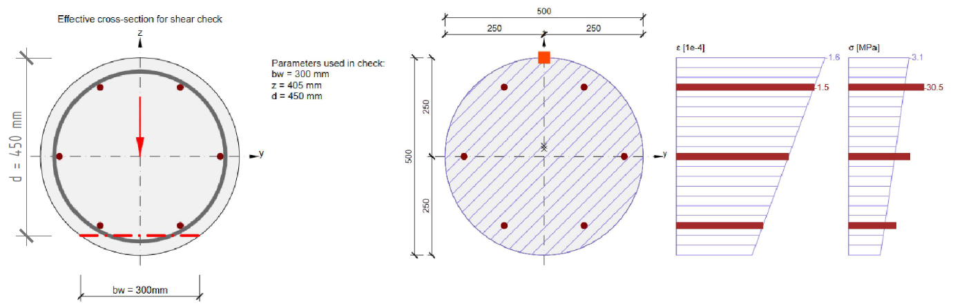
Als de toestand zonder buigscheuren wordt verwaarloosd - zie de figuur:
En als er geen trek- of drukkoord in de doorsnede aanwezig is (de gehele doorsnede staat onder druk of trek), is bw de breedte van de doorsnede op afstand d van de rand van de doorsnede. Waarbij d de effectieve hoogte is en berekend wordt als d=0.9*h voor doorsneden zonder trek- of drukkoord (volledig gedrukt of volledig getrokken).
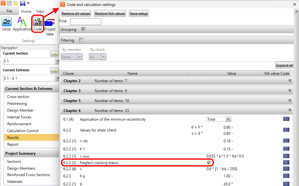
3. Methode
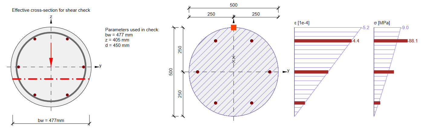
Als de toestand zonder buigscheuren in beschouwing wordt genomen (conform EN 1992-1-1 6.2.2(2)) en de doorsnede in de UGT niet door buigscheuren wordt beïnvloed. De waarde van bw wordt berekend op het niveau van de maximale hoofdtrekspanning.
4. Methode
Een doorsnede die door buigscheuren wordt beïnvloed, maar waarbij alleen de drukkoord of alleen de trekkoord aanwezig is - het gebied waarbinnen het programma de kleinste waarde van bw zoekt, wordt aan één zijde begrensd door het bestaande zwaartepunt van het beton in druk (of het zwaartepunt van de wapening in trek), de andere zijde van het gebied wordt bepaald door de afschuivingswapening.
5. Methode
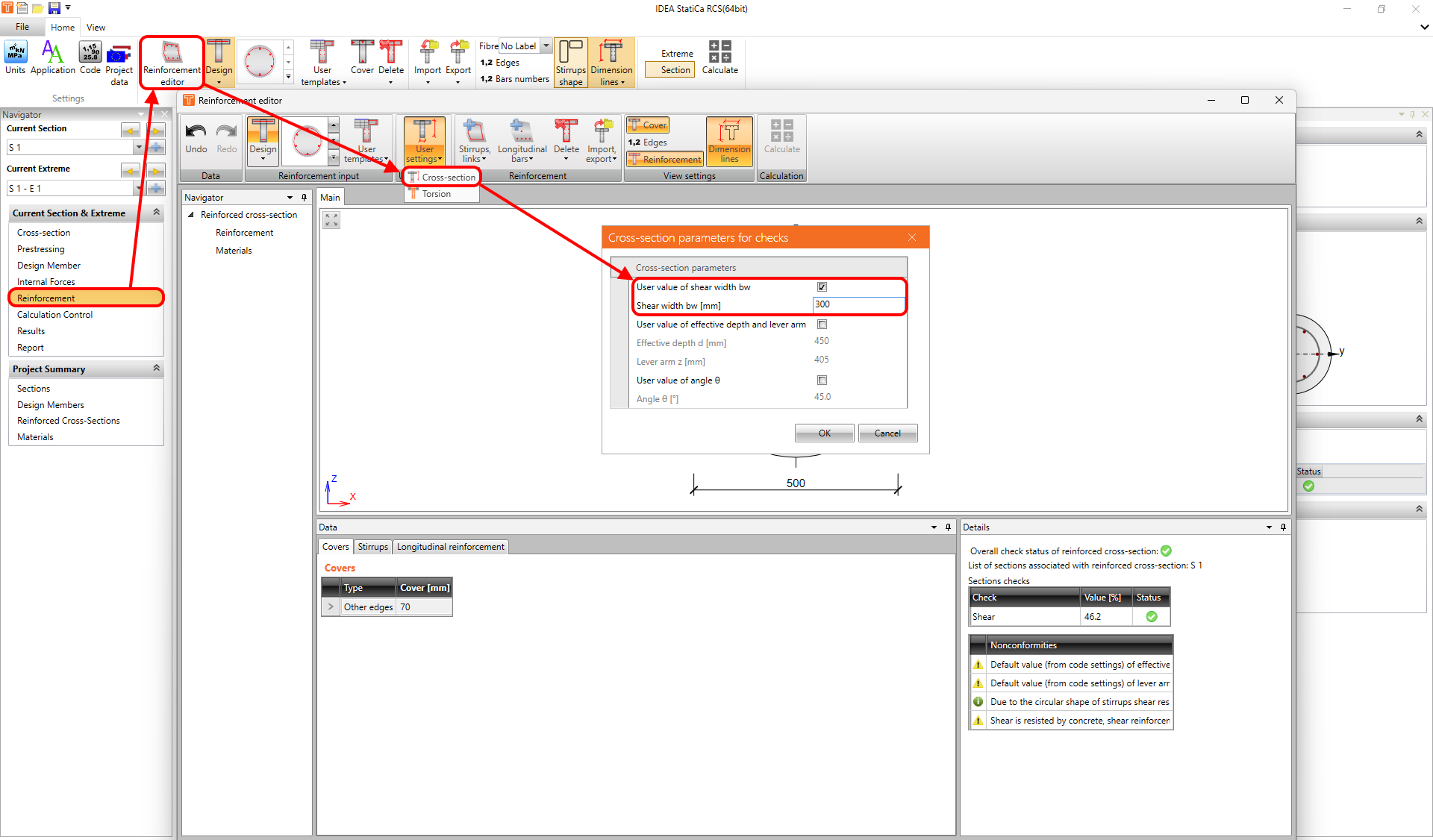
In sommige gevallen is het zinvol om de waarde van bw handmatig in te stellen. Dit kan worden gedaan in de Wapeningseditor.