Saldatura d'angolo nel collegamento con piastra d'anima
Descrizione
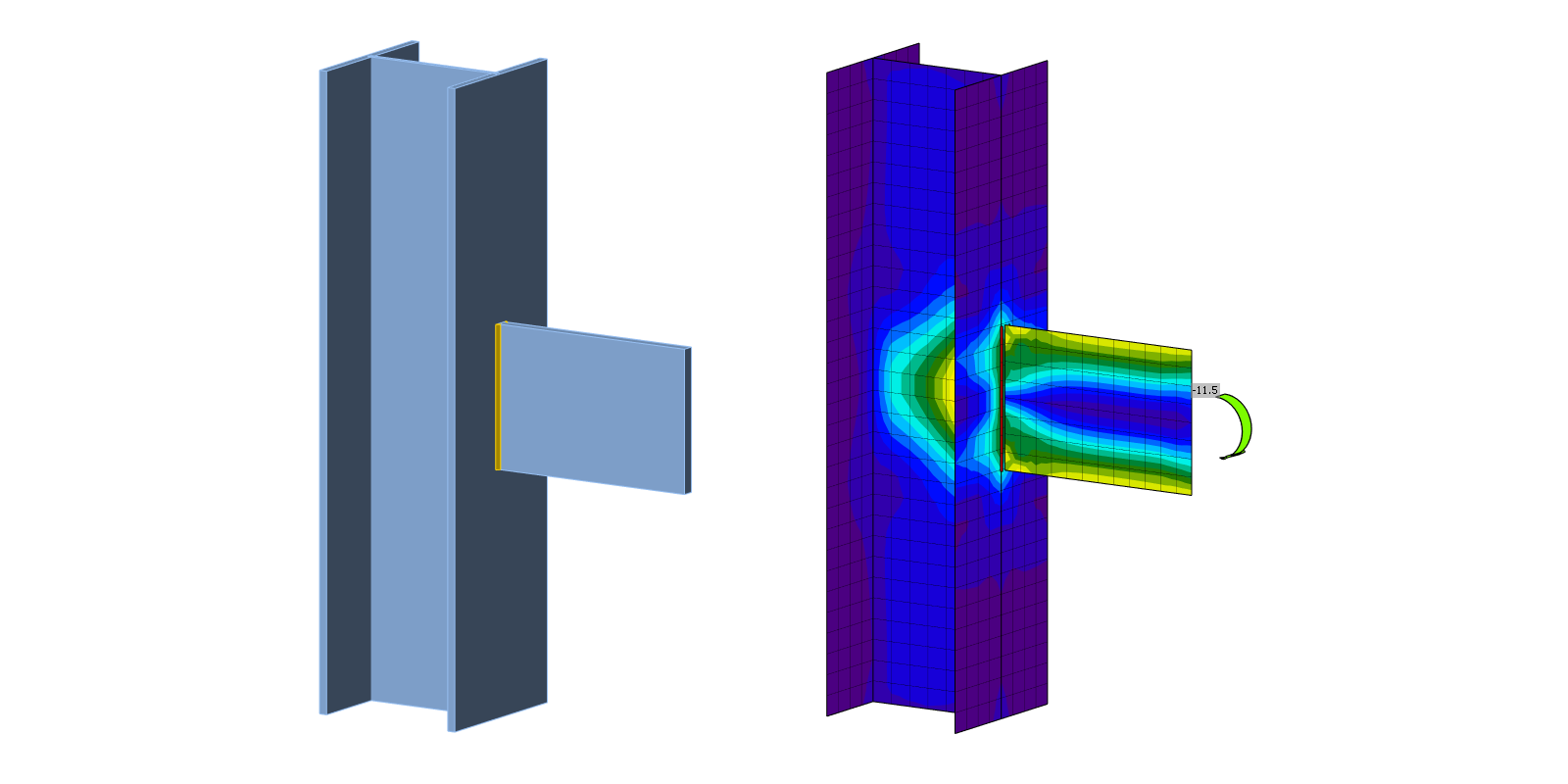
In questo capitolo, il metodo degli elementi finiti basato sui componenti (CBFEM) di una saldatura d'angolo in un collegamento con piastra d'anima viene verificato con il metodo delle componenti (CM). Una piastra d'anima è saldata a una colonna a sezione aperta HEB. L'altezza della piastra d'anima varia da 150 a 300 mm. La piastra/saldatura è caricata da forza normale, forza di taglio e momento flettente.
Modello analitico
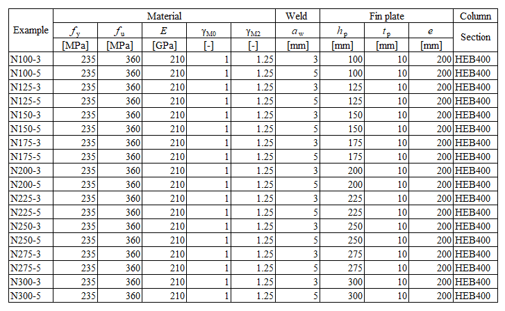
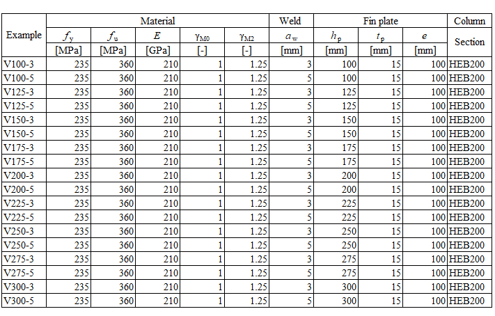
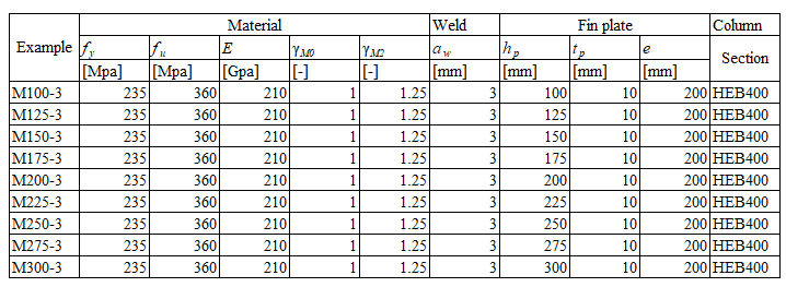
La saldatura d'angolo è l'unica componente esaminata nello studio. Le saldature sono progettate per essere la componente più debole del giunto secondo il Capitolo 4 della EN 1993-1-8:2005. La resistenza di progetto della saldatura d'angolo è descritta nella Sezione 4.1. Una panoramica degli esempi considerati e del materiale è riportata nella Tab. 4.3.1. Sono considerati tre casi di carico: forza normale N, forza di taglio V e momento flettente M. La geometria del giunto con le dimensioni è mostrata nella Fig. 4.3.1.
Calcolo della resistenza normale della saldatura
\[\sqrt{ \sigma_{\perp}^2 + 3 \cdot \left( \tau_{\perp}^2 + \tau_{\parallel}^2\right)} \leq \frac{f_u}{\beta_{\mathrm{w}} \cdot \gamma_{\mathrm{M2}}}\]
\[\sigma_{\perp} = \tau_{\perp} = \frac{\sigma_{N}}{\sqrt{2}} = \frac{N}{l \cdot a}\cdot \frac{1}{\sqrt{2}} \]
\[ \tau_{\parallel} = 0\]
\[ \sqrt{ \left( \frac{\sigma_{N}}{\sqrt{2}} \right)^2 + 3 \cdot \left( \frac{\sigma_{N}}{\sqrt{2}} \right)^2} \leq \frac{f_u}{\beta_{\mathrm{w}} \cdot \gamma_{\mathrm{M2}}}\]
\[ \sqrt{ \left( \frac{N}{l \cdot a}\cdot \frac{1}{\sqrt{2}} \right)^2 + 3 \cdot \left( \frac{N}{l_\mathrm{tw} \cdot a}\cdot \frac{1}{\sqrt{2}} \right)^2} \leq \frac{f_u}{\beta_{\mathrm{w}} \cdot \gamma_{\mathrm{M2}}}\]
\[ N \leq \frac{f_{u} \cdot l\cdot a }{\beta_{\mathrm{w}} \cdot \gamma_{\mathrm{M2}} \cdot \sqrt{2}} \]
\[ \sigma_{\perp} \leq \frac{f_{u} \cdot 0.9}{ \gamma_{\mathrm{M2}}} \]
\[ N \leq \frac{f_{u} \cdot l \cdot a \cdot 0.9 \cdot \sqrt{2}}{ \gamma_{\mathrm{M2}} } \]
Dove:
\(a\) - spessore di gola della saldatura
\(N\) - forza normale agente sull'elemento
\(l\) - lunghezza totale della saldatura
\(\beta_{\mathrm{w}}\) - fattore di correlazione ricavato dalla Tabella 4.1 della EN 1993-1-8
\(f_u\) - resistenza ultima a trazione nominale della parte più debole collegata
\(\gamma_{\mathrm{M2}}\) - fattore parziale di sicurezza per le saldature
Calcolo della resistenza a flessione della saldatura
\[\sqrt{ \sigma_{\perp}^2 + 3 \cdot \left( \tau_{\perp}^2 + \tau_{\parallel}^2\right)} \leq \frac{f_u}{\beta_{\mathrm{w}} \cdot \gamma_{\mathrm{M2}}}\]
\[\sigma_{\perp} = \tau_{\perp} = \frac{\sigma_{N}}{\sqrt{2}} = \frac{M}{W}\cdot \frac{1}{\sqrt{2}} \]
\[ \tau_{\parallel} = 0\]
\[ \sqrt{ \left( \frac{\sigma_{N}}{\sqrt{2}} \right)^2 + 3 \cdot \left( \frac{\sigma_{N}}{\sqrt{2}} \right)^2} \leq \frac{f_u}{\beta_{\mathrm{w}} \cdot \gamma_{\mathrm{M2}}}\]
\[ \sqrt{ \left( \frac{M}{W}\cdot \frac{1}{\sqrt{2}} \right)^2 + 3 \cdot \left( \frac{M}{W}\cdot \frac{1}{\sqrt{2}} \right)^2} \leq \frac{f_u}{\beta_{\mathrm{w}} \cdot \gamma_{\mathrm{M2}}}\]
\[ M \leq \frac{f_{u} \cdot W }{\beta_{\mathrm{w}} \cdot \gamma_{\mathrm{M2}} \cdot \sqrt{2}} \]
\[ \sigma_{\perp} \leq \frac{f_{u} \cdot 0.9}{ \gamma_{\mathrm{M2}}} \]
\[ M \leq \frac{f_{u} \cdot W \cdot 0.9 \cdot \sqrt{2}}{ \gamma_{\mathrm{M2}} } \]
Dove:
\(a\) - spessore di gola della saldatura
\(W = \frac{1}{4} \cdot a \cdot l^2\) - modulo di resistenza plastico della saldatura
\(M\) - momento flettente agente sull'elemento
\(l\) - lunghezza totale della saldatura
\(\beta_{\mathrm{w}}\) - fattore di correlazione ricavato dalla Tabella 4.1 della EN 1993-1-8
\(f_u\) - resistenza ultima a trazione nominale della parte più debole collegata
\(\gamma_{\mathrm{M2}}\) - fattore parziale di sicurezza per le saldature
Calcolo della resistenza a taglio della saldatura
\[\sqrt{ \sigma_{\perp}^2 + 3 \cdot \left( \tau_{\perp}^2 + \tau_{\parallel}^2\right)} \leq \frac{f_u}{\beta_{\mathrm{w}} \cdot \gamma_{\mathrm{M2}}}\]
\[\sigma_{\perp} = \tau_{\perp} = 0 \]
\[ \tau_{\parallel} = \frac{V}{l \cdot a}\]
\[ \sqrt{ 3 \cdot \left( \tau_{\parallel} \right)^2} \leq \frac{f_u}{\beta_{\mathrm{w}} \cdot \gamma_{\mathrm{M2}}}\]
\[ \sqrt{ 3 \cdot \left( \frac{V}{l \cdot a}\right)^2} \leq \frac{f_u}{\beta_{\mathrm{w}} \cdot \gamma_{\mathrm{M2}}}\]
\[ V = \frac{f_u \cdot l\cdot a }{\beta_{\mathrm{w}} \cdot \gamma_{\mathrm{M2}} \cdot \sqrt{3}} \]
Dove:
\(a\) - spessore di gola della saldatura
\(V\) - forza di taglio agente sull'elemento
\(l\) - lunghezza totale della saldatura
\(\beta_{\mathrm{w}}\) - fattore di correlazione ricavato dalla Tabella 4.1 della EN 1993-1-8
\(f_u\) - resistenza ultima a trazione nominale della parte più debole collegata
\(\gamma_{\mathrm{M2}}\) - fattore parziale di sicurezza per le saldature
\[ \textsf{\textit{\footnotesize{Tab. 4.3.1.N Examples overview}}}\]
\[ \textsf{\textit{\footnotesize{Tab. 4.3.1.V Examples overview}}}\]
\[ \textsf{\textit{\footnotesize{Tab. 4.3.1.M Examples overview}}}\]
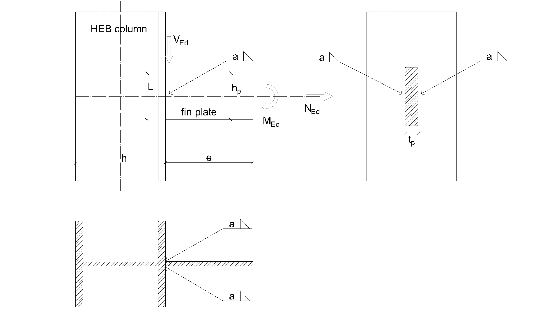
\[ \textsf{\textit{\footnotesize{Fig. 4.3.1 Joint geometry with dimensions}}}\]
Modello numerico
La componente saldatura nel CBFEM è descritta nel Background teorico generale e nel Background teorico EN. Il modello di saldatura ha un diagramma di materiale elasto-plastico e i picchi di tensione vengono ridistribuiti lungo la lunghezza della saldatura.
Verifica della resistenza
La resistenza di progetto calcolata con il CBFEM viene confrontata con i risultati del CM. Il confronto è presentato nella Tab. 4.3.2. Lo studio è condotto per un parametro: la lunghezza della saldatura, ovvero l'altezza della piastra d'anima, e tre casi di carico: forza normale, forza di taglio e momento flettente. La forza di taglio è applicata nel piano della saldatura per trascurare l'effetto di un momento flettente aggiuntivo. Il momento flettente è applicato all'estremità della piastra d'anima. L'influenza della lunghezza della saldatura sulla resistenza di progetto dei giunti con piastra d'anima caricati da forza normale e forza di taglio è mostrata nella Fig. 4.3.2. La relazione tra la lunghezza della saldatura e la resistenza a momento flettente del giunto è mostrata nella Fig. 4.3.3.
\[ \textsf{\textit{\footnotesize{Tab. 4.3.2 Comparison of CBFEM and CM}}}\]
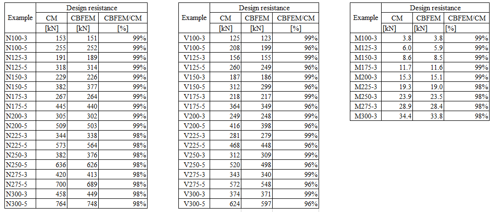
I risultati del CBFEM e del CM vengono confrontati e viene presentato lo studio di sensibilità. L'influenza della lunghezza della saldatura sulla resistenza di progetto in un giunto con piastra d'anima caricato da forza normale è mostrata nella Fig. 4.3.2, da forza di taglio nella Fig. 4.3.3 e da momento flettente nella Fig. 4.3.4. Lo studio mostra una buona concordanza per tutti i casi di carico applicati.
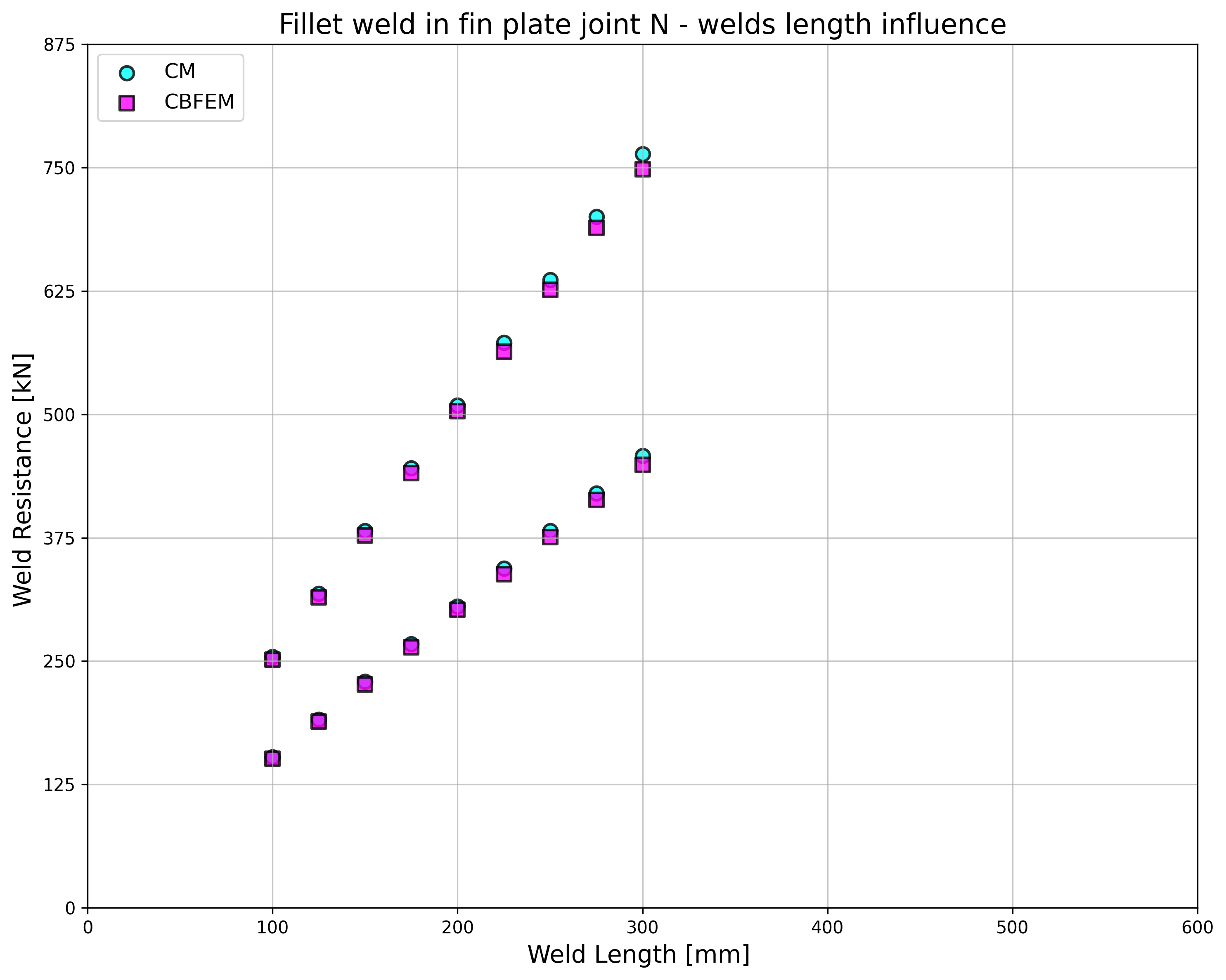
\[ \textsf{\textit{\footnotesize{Fig. 4.3.2 Parametric study of fin plate joint loaded by normal force}}}\]
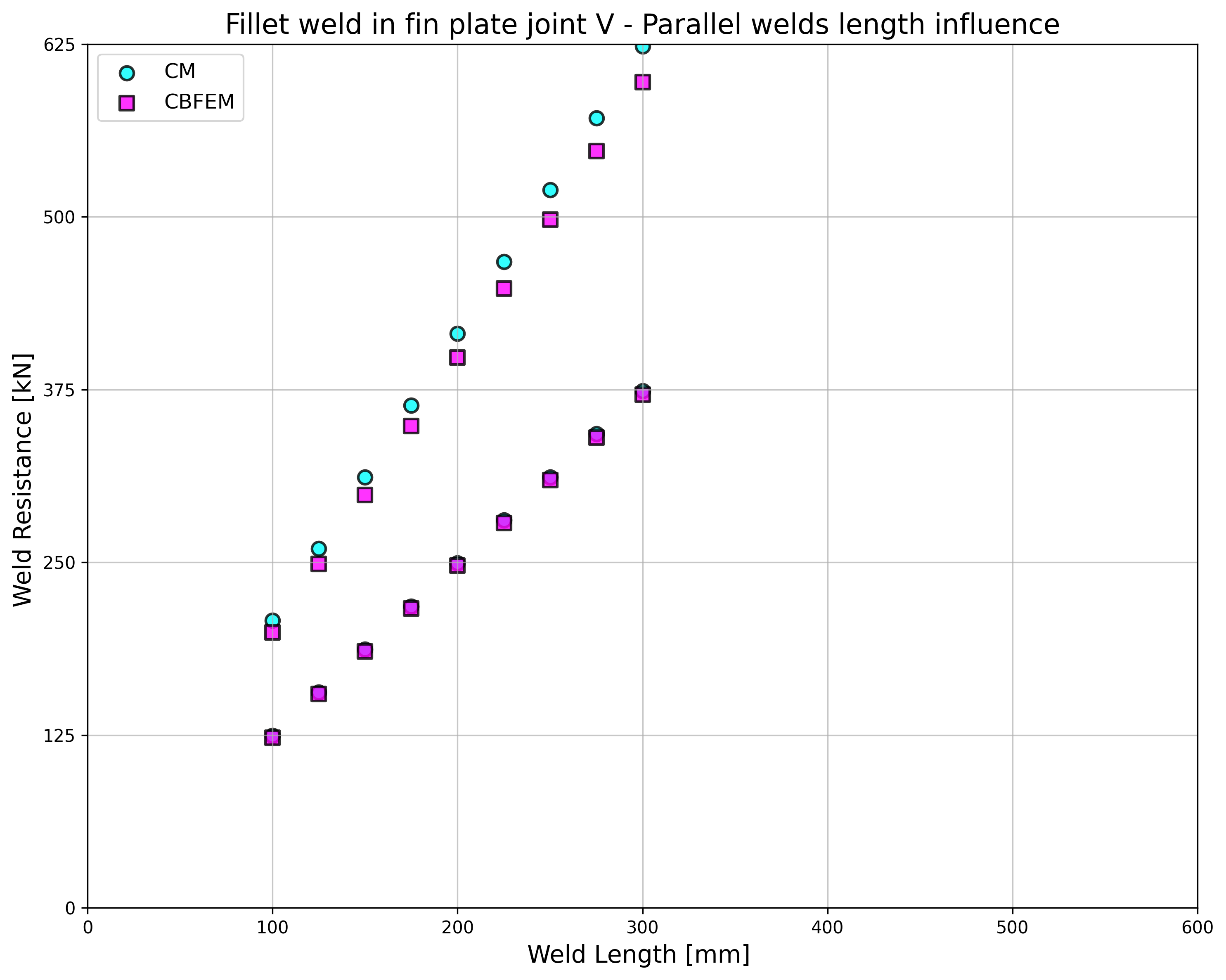
\[ \textsf{\textit{\footnotesize{Fig. 4.3.3 Parametric study of fin plate joint loaded by shear force}}}\]
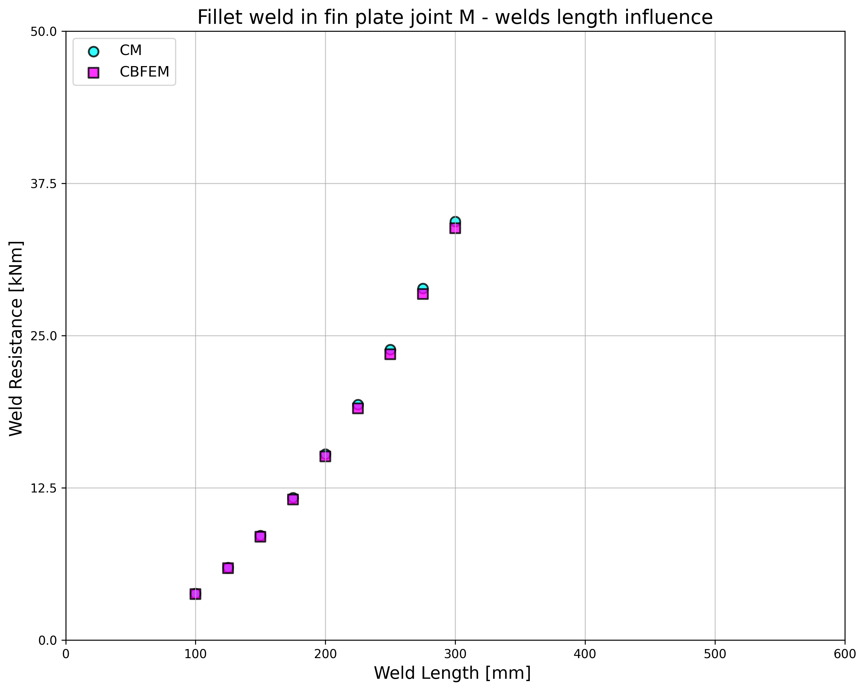
\[ \textsf{\textit{\footnotesize{Fig. 4.3.4 Parametric study of fin plate joint loaded by bending moment}}}\]
Per illustrare l'accuratezza del modello CBFEM, i risultati degli studi parametrici sono riassunti in un diagramma che confronta le resistenze di progetto del CBFEM e del CM; vedere Fig. 4.3.5. I risultati mostrano che la differenza tra i due metodi di calcolo è in tutti i casi inferiore al 10 %.

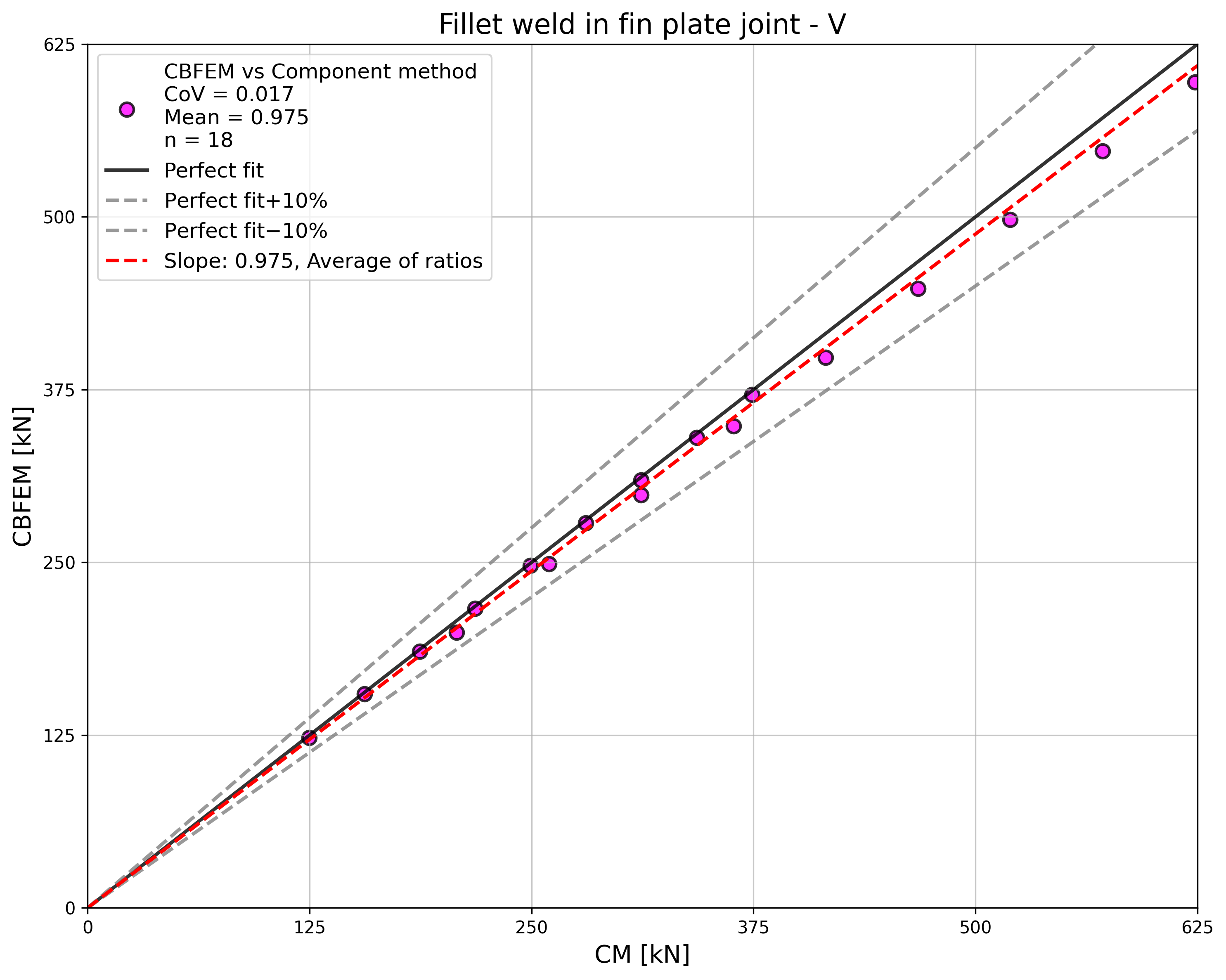
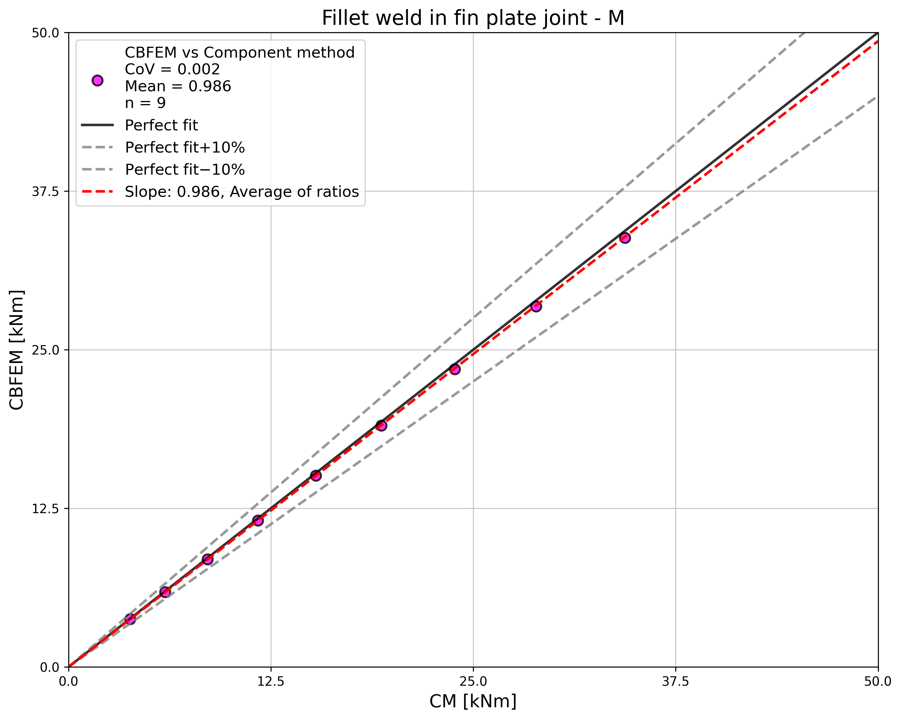
\[ \textsf{\textit{\footnotesize{Fig. 4.3.5 Verification of CBFEM to CM}}}\]
Esempio di riferimento
Dati di input
Colonna
- Acciaio S235
- HEB 400
Piastra d'anima
- Spessore tp = 15 mm
- Altezza hp = 175 mm
Saldatura, doppia saldatura d'angolo, vedere Fig. 4.3.6
- Spessore di gola aw = 3 mm
Risultati
- Resistenza di progetto a flessione pura MRd = 11,4 kNm
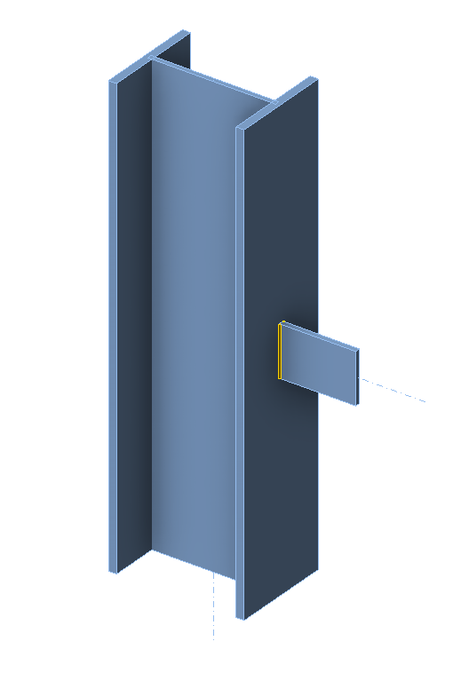
\[ \textsf{\textit{\footnotesize{Fig. 4.3.6 Benchmark example for the welded fin plate joint}}}\]