Collegamento bullonato - Giunti a taglio
Descrizione
Questo studio è incentrato sulla verifica del metodo degli elementi finiti basato sui componenti (CBFEM) per la resistenza del collegamento bullonato a doppio giunto simmetrico rispetto a un modello analitico (AM).
Modello analitico
La resistenza del bullone a taglio e la resistenza della piastra a rifollamento sono progettate secondo la Tab. 3.4 nel capitolo 3.6.1 della EN 1993-1-8:2005. Per i collegamenti lunghi, si considera il fattore di riduzione secondo il punto 3.8. La resistenza di progetto degli elementi collegati con riduzioni per i fori degli elementi di fissaggio è presa in considerazione secondo il punto 3.10.
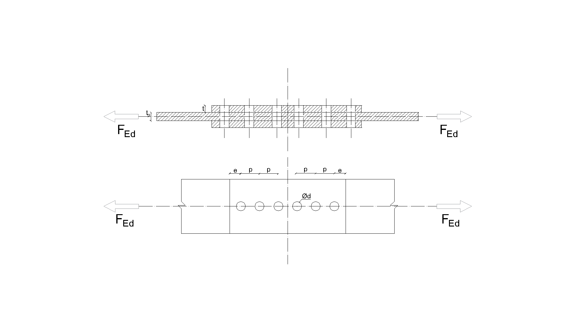
\[ \textsf{\textit{\footnotesize{ Drawing 5.2.1 Joint geometry and dimensions}}}\]
Verifica della resistenza
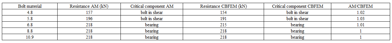
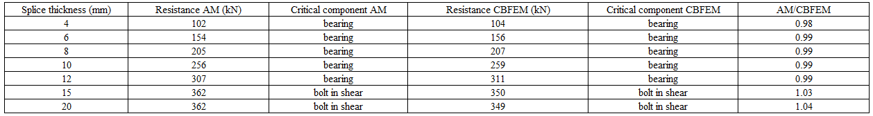
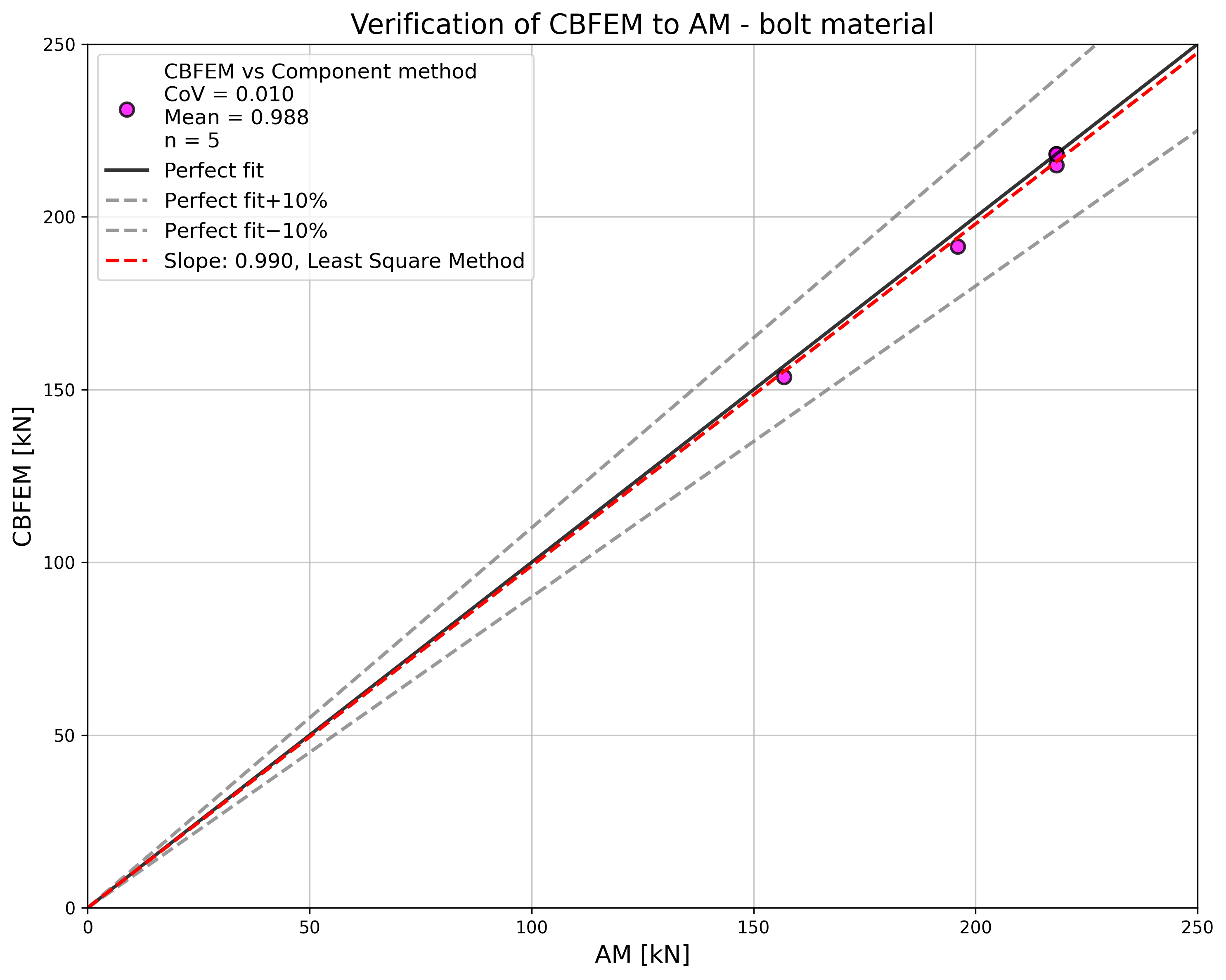
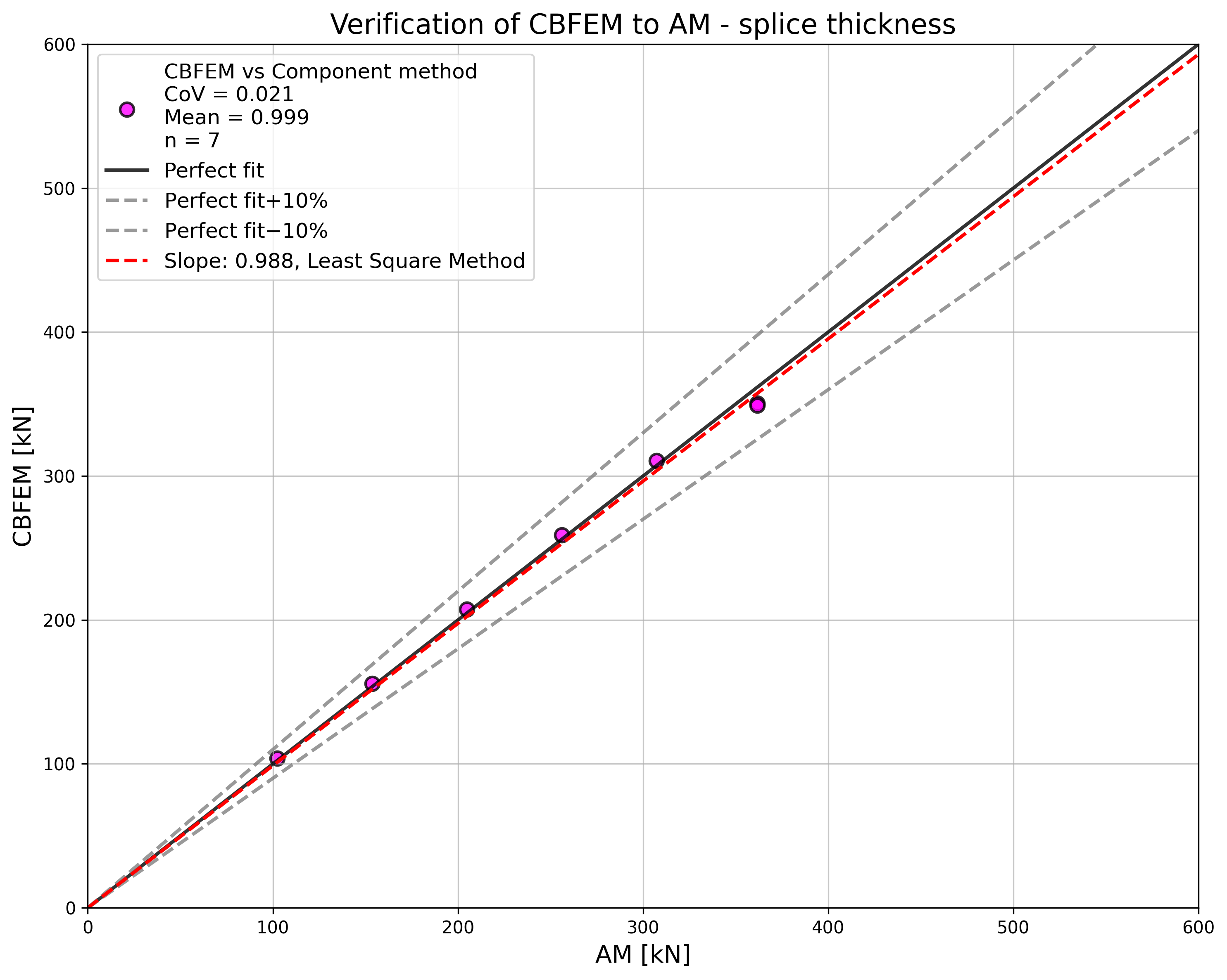
Le resistenze di progetto calcolate con il CBFEM sono state confrontate con i risultati del modello analitico (AM). I risultati sono riassunti nella Tab. 5.2.1. I parametri sono il materiale del bullone, lo spessore del giunto, il diametro del bullone e le distanze tra i bulloni, vedere le Fig. da 5.2.1 a 5.2.4.
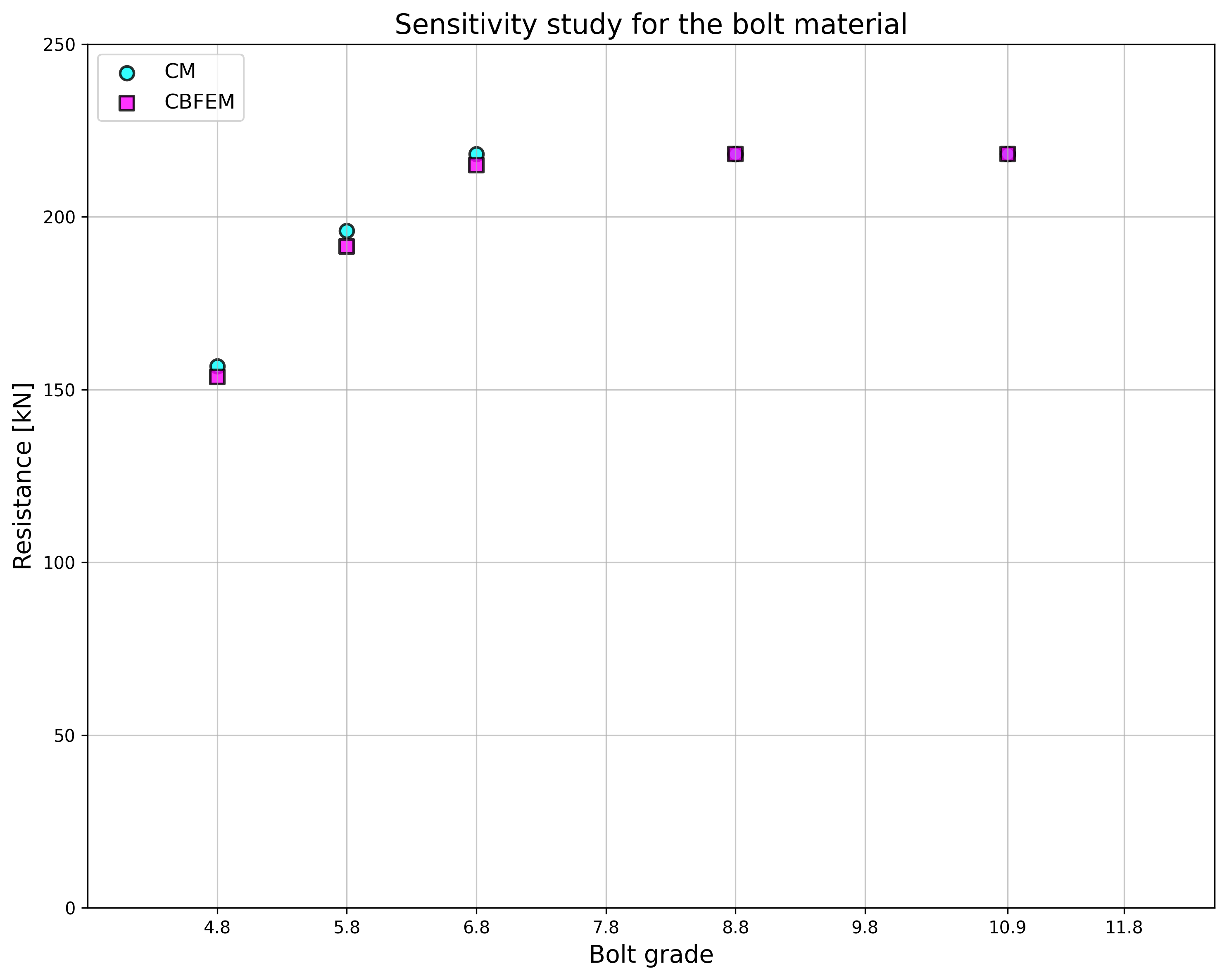
\[ \textsf{\textit{\footnotesize{Fig. 5.2.1 Sensitivity study for the bolt material}}}\]
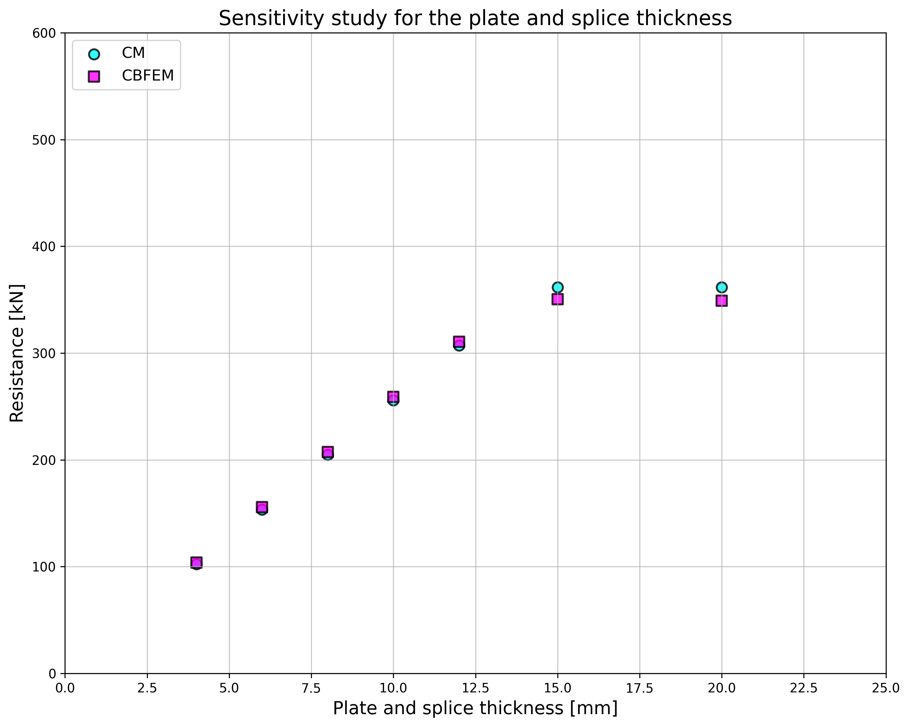
\[ \textsf{\textit{\footnotesize{Fig. 5.2.2 Sensitivity study for the splice thickness}}}\]
Tab. 5.2.1 Studio di sensibilità della resistenza
Descrizione del giunto: giunto 150/10mm, bulloni 2×M20 a distanze p =70, e1=50, piastre 2×150/6mm, acciaio S235
Descrizione del giunto: altezza del giunto 200mm, bulloni 3×M16 8,8 a distanze p = 55mm e1 = 40mm, piastre 2×200/t mm, acciaio S235
Descrizione del giunto: giunto 120/10mm, bulloni 2×MX 8,8, piastre 2×120/10 mm, acciaio S235

Descrizione del giunto: Giunto 200/6 mm, bulloni 3×M16 8,8, piastre 2×200/6mm, acciaio S235


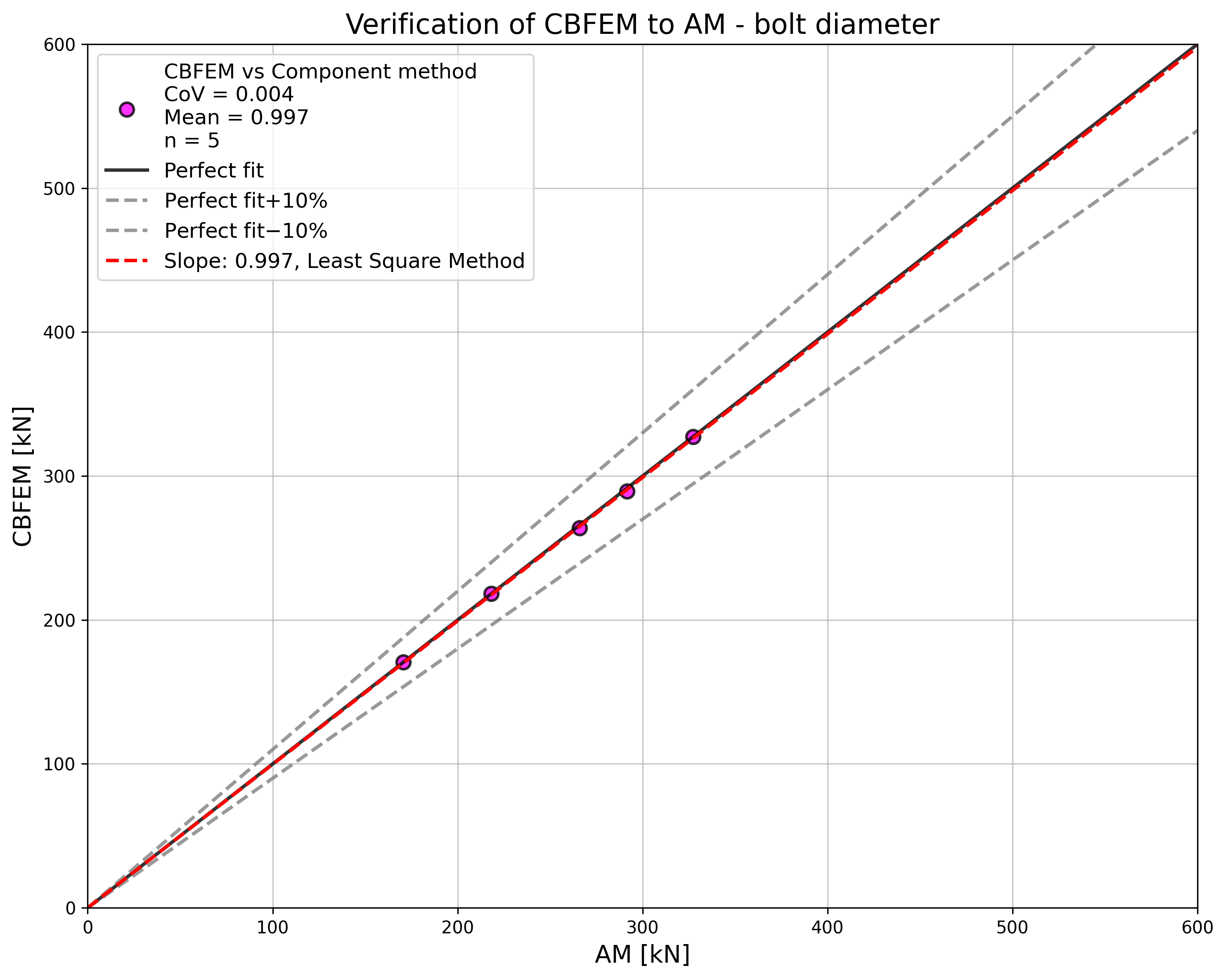
\[ \textsf{\textit{\footnotesize{Fig. 5.2.3 Sensitivity study for the bolt diameter}}}\]

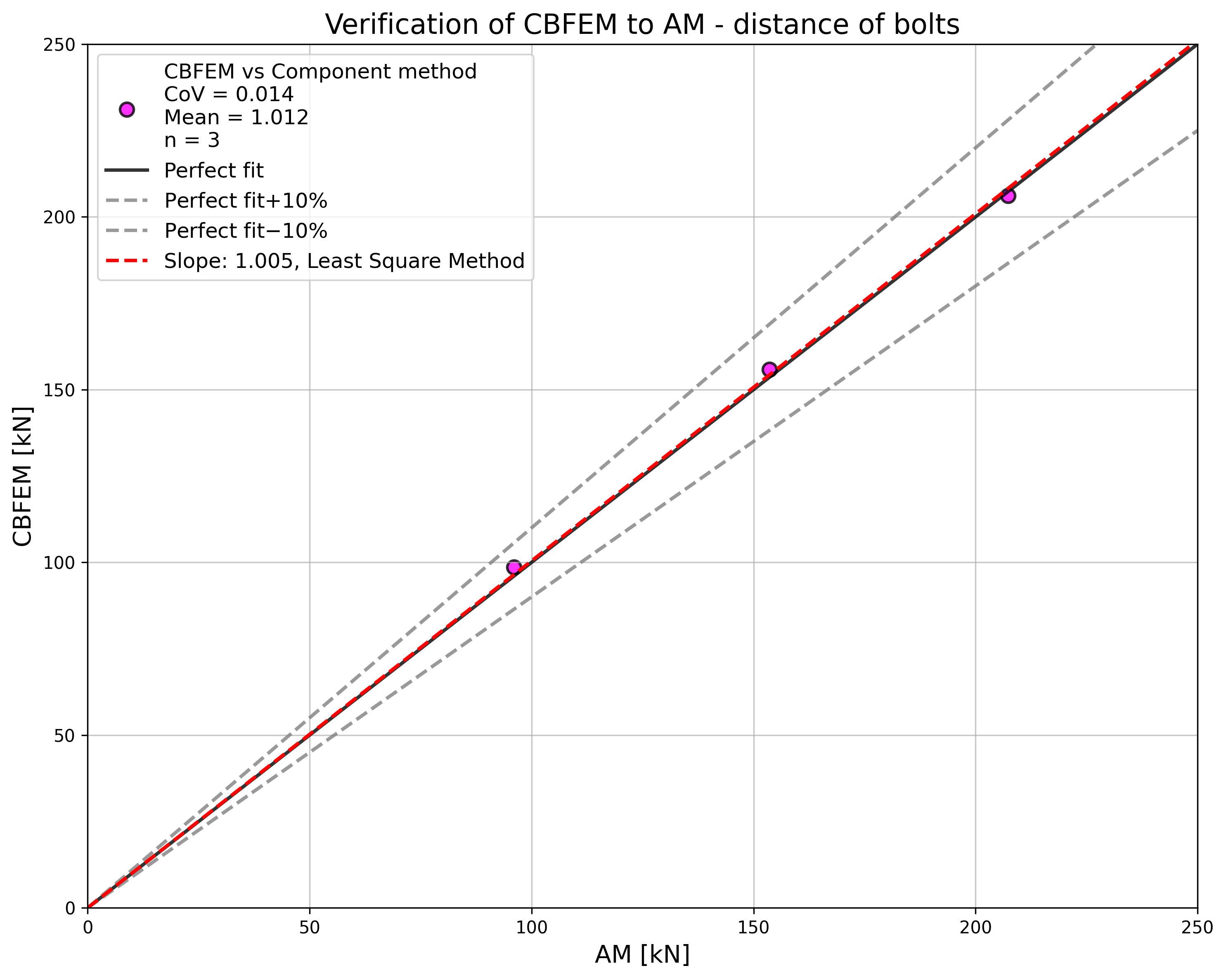
\[ \textsf{\textit{\footnotesize{Fig. 5.2.4 Sensitivity study for the distance of bolts}}}\]
I risultati degli studi di sensibilità sono riassunti nel grafico in Fig. 5.2.5. I risultati mostrano che le differenze tra i due metodi di calcolo sono inferiori al 5 %. Il modello analitico fornisce generalmente una resistenza maggiore.
\[ \textsf{\textit{\footnotesize{Fig. 5.2.5 Verification of CBFEM to AM for the symmetrical double splice connection}}}\]
Esempio di riferimento
Dati di input
Elemento collegato
- Acciaio S235
- Giunto 200/10 mm
Connettori
Bulloni
- 3 × M16 8.8
- Distanze e1 = 40 mm, p = 55 mm
2 x giunto
- Acciaio S235
- Piastra 380×200×10
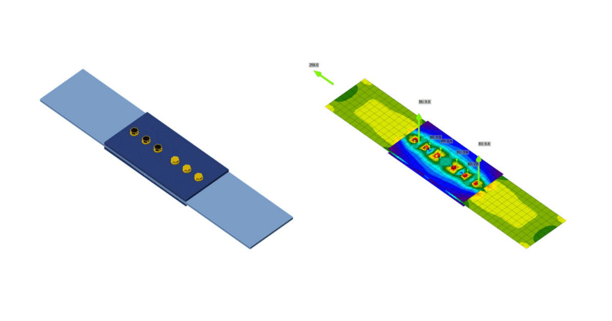
Risultati
- Resistenza di progetto FRd = 258 kN
- Critica è la pressione sul foro del giunto collegato
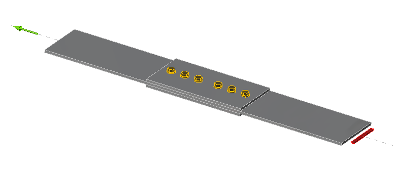
\[ \textsf{\textit{\footnotesize{Fig. 5.2.6 Benchmark example of the bolted splices in shear}}}\]