Ligação aparafusada - Emendas ao corte
Descrição
Este estudo é dedicado à verificação do método dos elementos finitos baseado em componentes (CBFEM) para a resistência da ligação aparafusada de emenda dupla simétrica, comparando com um modelo analítico (MA).
Modelo analítico
A resistência do parafuso ao corte e a resistência da chapa ao esmagamento são calculadas de acordo com o Quadro 3.4 do capítulo 3.6.1 da EN 1993-1-8:2005. Para ligações longas, é considerado o fator de redução de acordo com a cl. 3.8. A resistência de cálculo dos elementos ligados com reduções para furos de fixadores é tida em conta de acordo com a cl. 3.10.
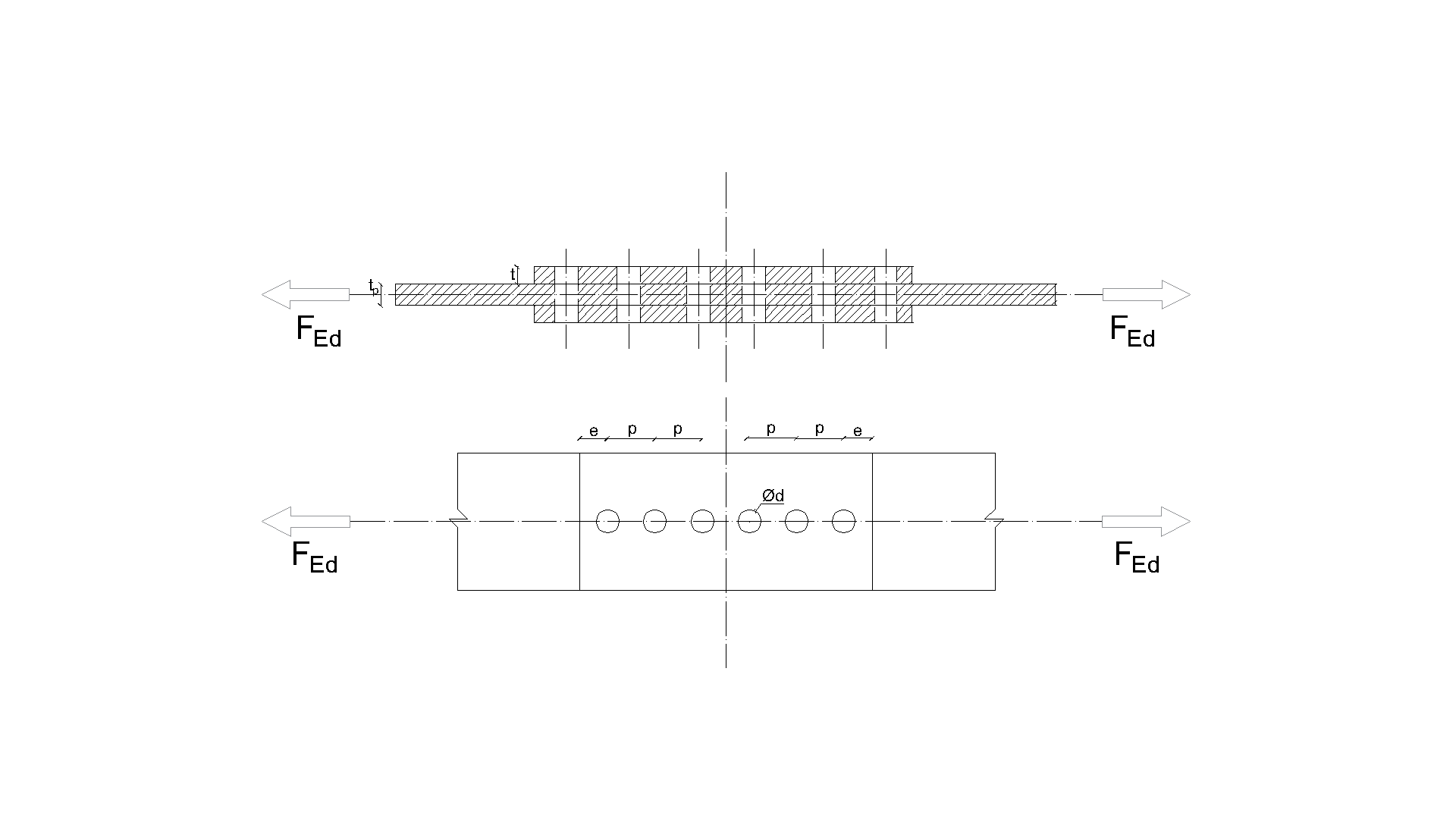
\[ \textsf{\textit{\footnotesize{ Drawing 5.2.1 Joint geometry and dimensions}}}\]
Verificação da resistência
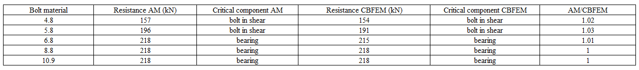
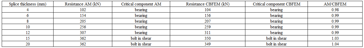
As resistências de cálculo calculadas pelo CBFEM foram comparadas com os resultados do modelo analítico (MA). Os resultados estão resumidos no Quadro 5.2.1. Os parâmetros são o material do parafuso, a espessura da emenda, o diâmetro do parafuso e as distâncias entre parafusos, ver Figs. 5.2.1 a 5.2.4.
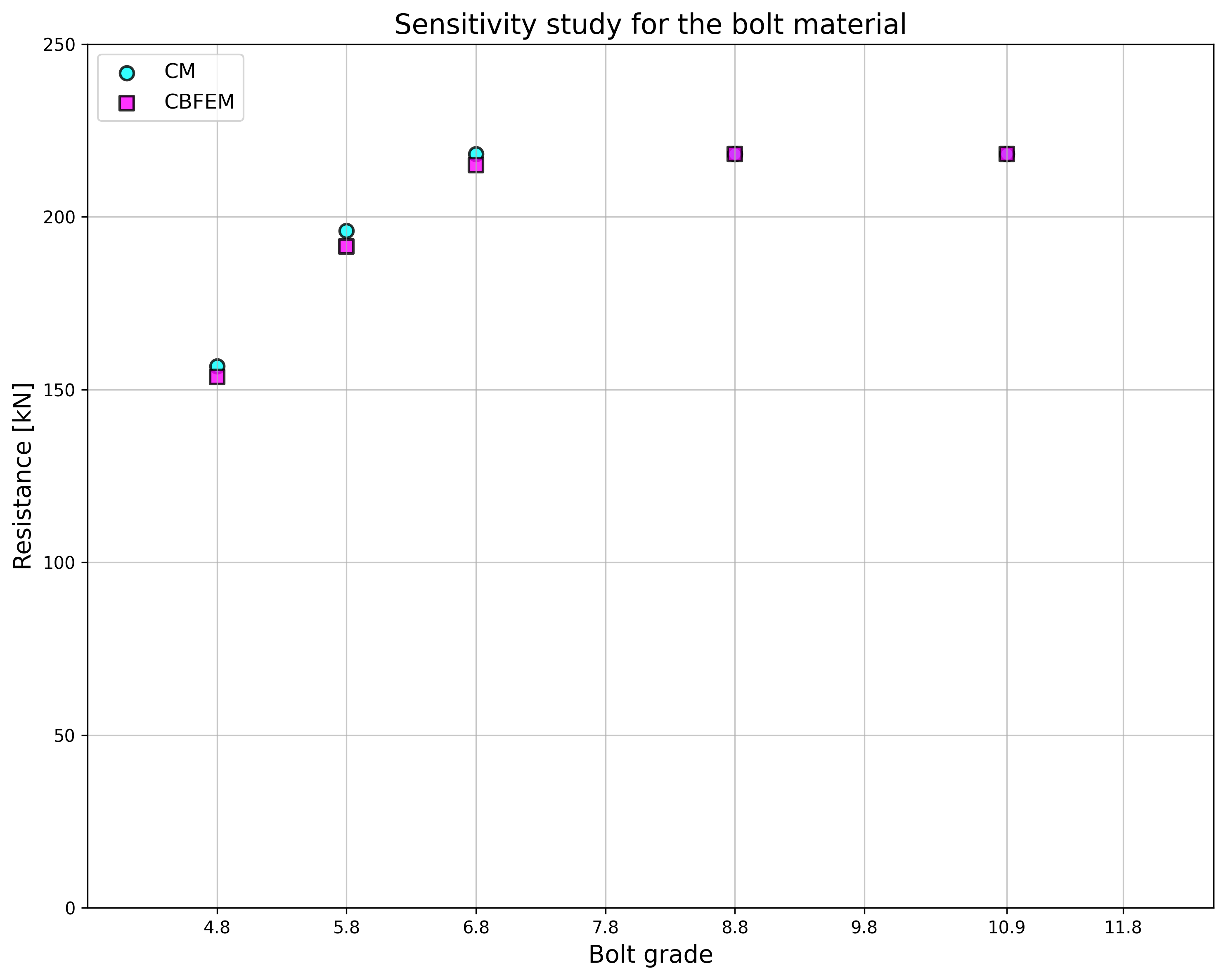
\[ \textsf{\textit{\footnotesize{Fig. 5.2.1 Sensitivity study for the bolt material}}}\]
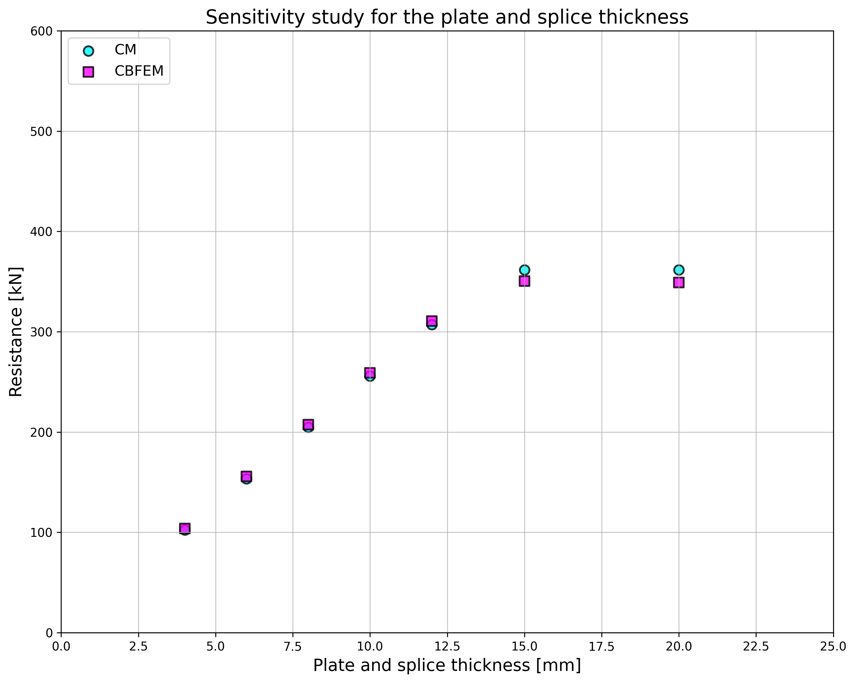
\[ \textsf{\textit{\footnotesize{Fig. 5.2.2 Sensitivity study for the splice thickness}}}\]
Quadro 5.2.1 Estudo de sensibilidade da resistência
Descrição da junta: emenda 150/10mm, parafusos 2×M20 com distâncias p =70, e1=50, chapas 2×150/6mm, aço S235
Descrição da junta: altura da emenda 200mm, parafusos 3×M16 8,8 com distâncias p = 55mm e1 = 40mm, chapas 2×200/t mm, aço S235
Descrição da junta: emenda 120/10mm, parafusos 2×MX 8,8, chapas 2×120/10 mm, aço S235

Descrição da junta: emenda 200/6 mm, parafusos 3×M16 8,8, chapas 2×200/6mm, aço S235


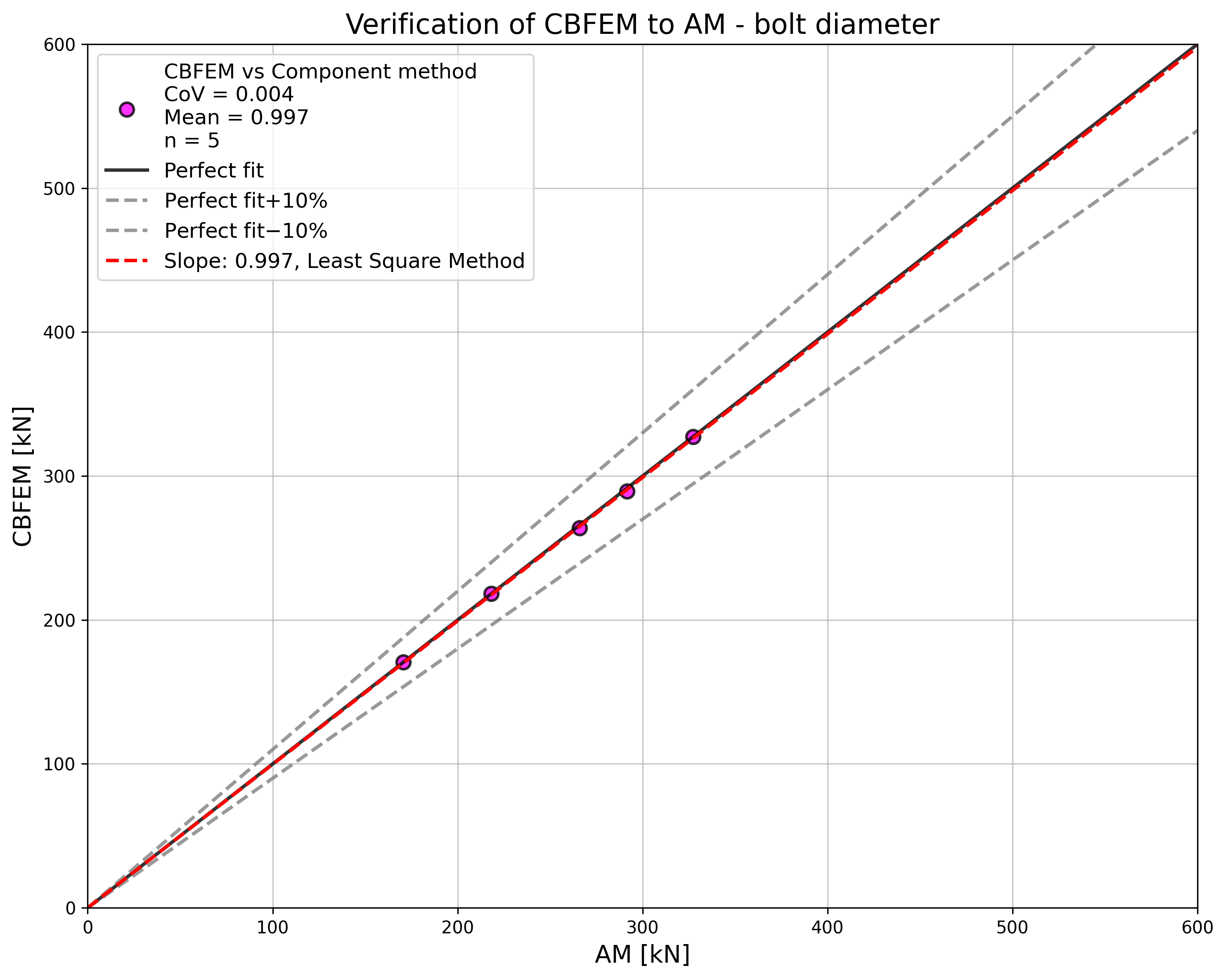
\[ \textsf{\textit{\footnotesize{Fig. 5.2.3 Sensitivity study for the bolt diameter}}}\]

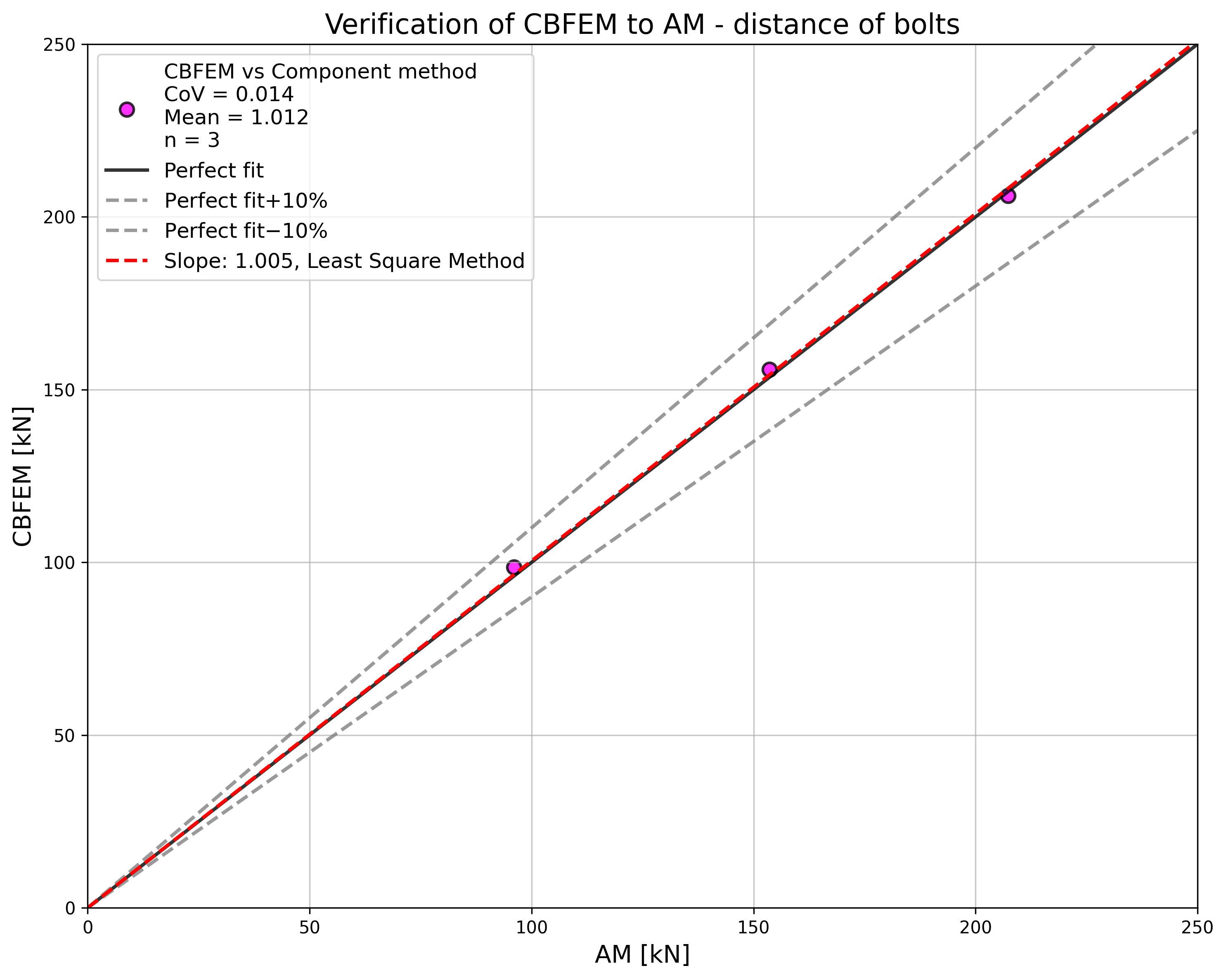
\[ \textsf{\textit{\footnotesize{Fig. 5.2.4 Sensitivity study for the distance of bolts}}}\]
Os resultados dos estudos de sensibilidade estão resumidos no gráfico da Fig. 5.2.5. Os resultados mostram que as diferenças entre os dois métodos de cálculo são inferiores a 5 %. O modelo analítico fornece geralmente uma resistência superior.
\[ \textsf{\textit{\footnotesize{Fig. 5.2.5 Verification of CBFEM to AM for the symmetrical double splice connection}}}\]
Exemplo de referência
Dados de entrada
Elemento ligado
- Aço S235
- Emenda 200/10 mm
Conectores
Parafusos
- 3 × M16 8.8
- Distâncias e1 = 40 mm, p = 55 mm
2 x emenda
- Aço S235
- Chapa 380×200×10
Resultados
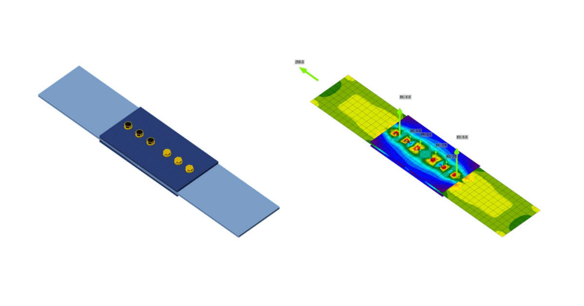
- Resistência de cálculo FRd = 258 kN
- Condicionante é o esmagamento da emenda ligada
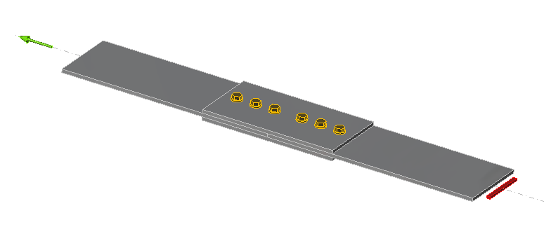
\[ \textsf{\textit{\footnotesize{Fig. 5.2.6 Benchmark example of the bolted splices in shear}}}\]