Progettazione senza problemi di colonne snelle in calcestruzzo
Introduzione
Cosa passa per la mente quando si deve progettare e verificare una colonna snella in calcestruzzo armato?
- Quale approccio scegliere, i metodi semplificati o quelli più precisi
- Utilizzare uno strumento software specializzato o i propri fogli Excel
- Se gli strumenti o i fogli Excel supportano una sezione trasversale in calcestruzzo armato di forma generale
- Come cogliere la perdita di stabilità di una colonna snella
Si potrebbe affermare che non ci si può affidare ai metodi semplificati e che si preferisce scegliere un approccio più accurato e sicuro basato sull'analisi non lineare. L'utilizzo di metodi più avanzati, la definizione delle non linearità materiali e geometriche sembrano tutti aspetti molto complicati e dispendiosi in termini di tempo.
O forse esiste uno strumento con cui è possibile progettare e verificare normativa colonne snelle in calcestruzzo in modo semplice, considerando al contempo il metodo più avanzato? Sì, esiste!
Scopri la nuova funzionalità Progettazione e verifica di colonne snelle secondo l'Eurocode in IDEA StatiCa Concrete.
Flusso di lavoro
Non è mai stato così semplice. Basta seguire il flusso di lavoro in quattro fasi per progettare e verificare normativa colonne snelle in calcestruzzo armato.
four-step workflow-GMNA


- Creare la geometria della struttura, inclusi i vincoli e l'armatura
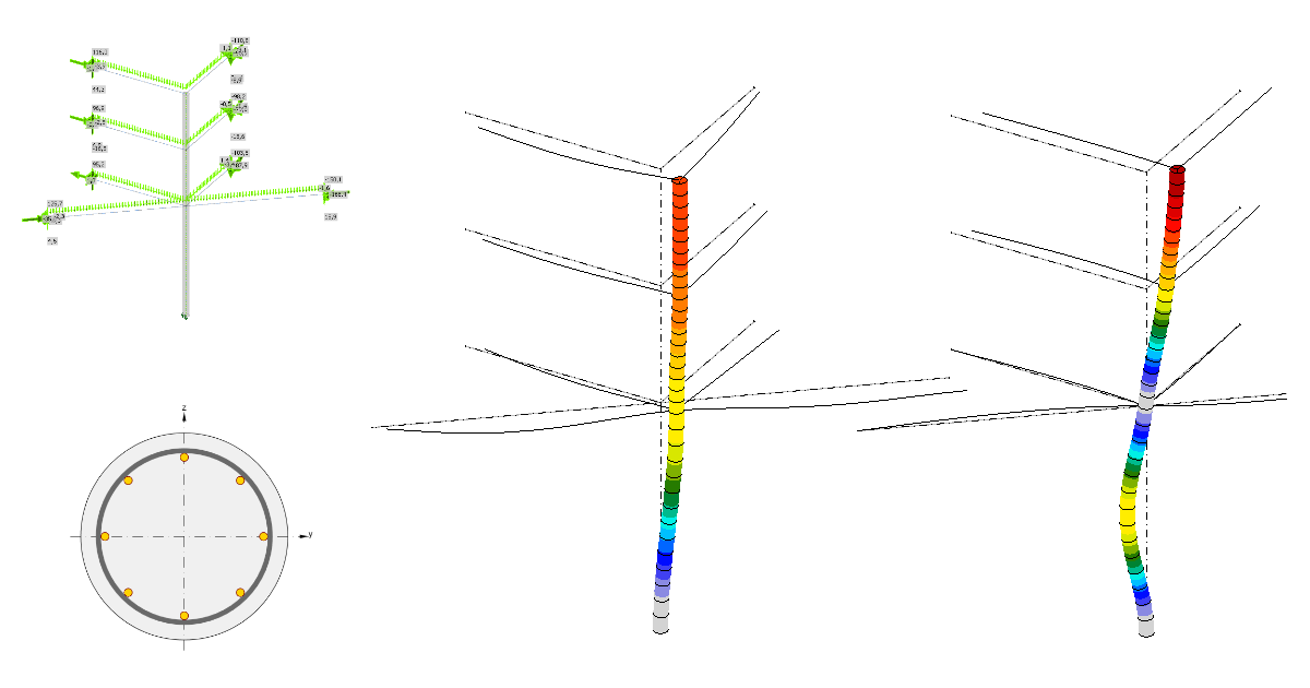
- Applicare gli effetti del carico all'elemento analizzato e agli elementi correlati
- Eseguire l'analisi non lineare e la verifica
- Generare il report con tutte le figure, i risultati e le verifiche importanti
Vorresti essere ancora più efficiente? Unisci i primi due passaggi più dispendiosi in termini di tempo in uno solo!
Utilizza il tuo software FEA preferito (SCIA Engineer, RFEM, AxisVM, SAP2000, Robot, ecc.) e collega la struttura analizzata con IDEA StatiCa Checkbot. Da Checkbot è possibile eseguire facilmente le analisi non lineari per progettare e verificare colonne snelle.
Metodo alla base
Il metodo si basa in realtà sulla valutazione delle tensioni e delle deformazioni nelle sezioni trasversali in calcestruzzo armato in cui un elemento analizzato viene automaticamente suddiviso. Tutto ciò di cui ci si deve occupare è armare correttamente l'elemento analizzato.
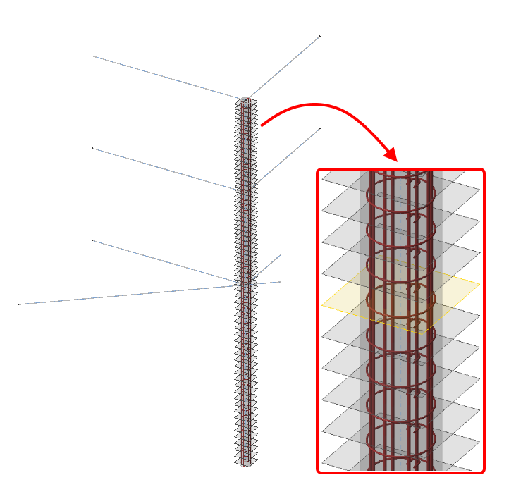
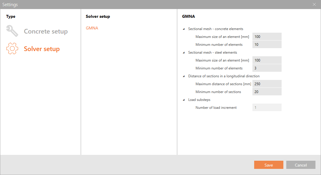
Ogni sezione in calcestruzzo armato viene automaticamente discretizzata con una rete secondo le impostazioni del solutore GMNA. I valori predefiniti sono disponibili nel pulsante delle impostazioni. Grazie alla corretta discretizzazione della sezione in calcestruzzo armato, si ottengono risultati molto dettagliati per ogni fibra di calcestruzzo e barra di armatura. È possibile influenzare la rete del calcestruzzo e dell'acciaio, nonché il numero di suddivisioni per lunghezza dell'elemento analizzato.
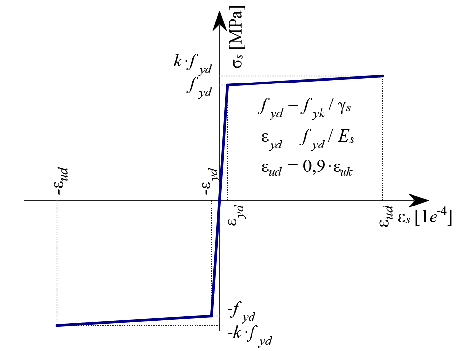
Il comportamento del calcestruzzo e dell'acciaio è descritto dai rispettivi diagrammi tensione-deformazione, rispettivamente parabolico-rettangolare e bilineare con ramo inclinato.

Il GMNA stesso comprende tre tipi di analisi:

- Analisi materialmente non lineare (MNA)
- Analisi lineare di instabilità (LBA)
- Analisi geometricamente e materialmente non lineare con imperfezioni (GMNIA)
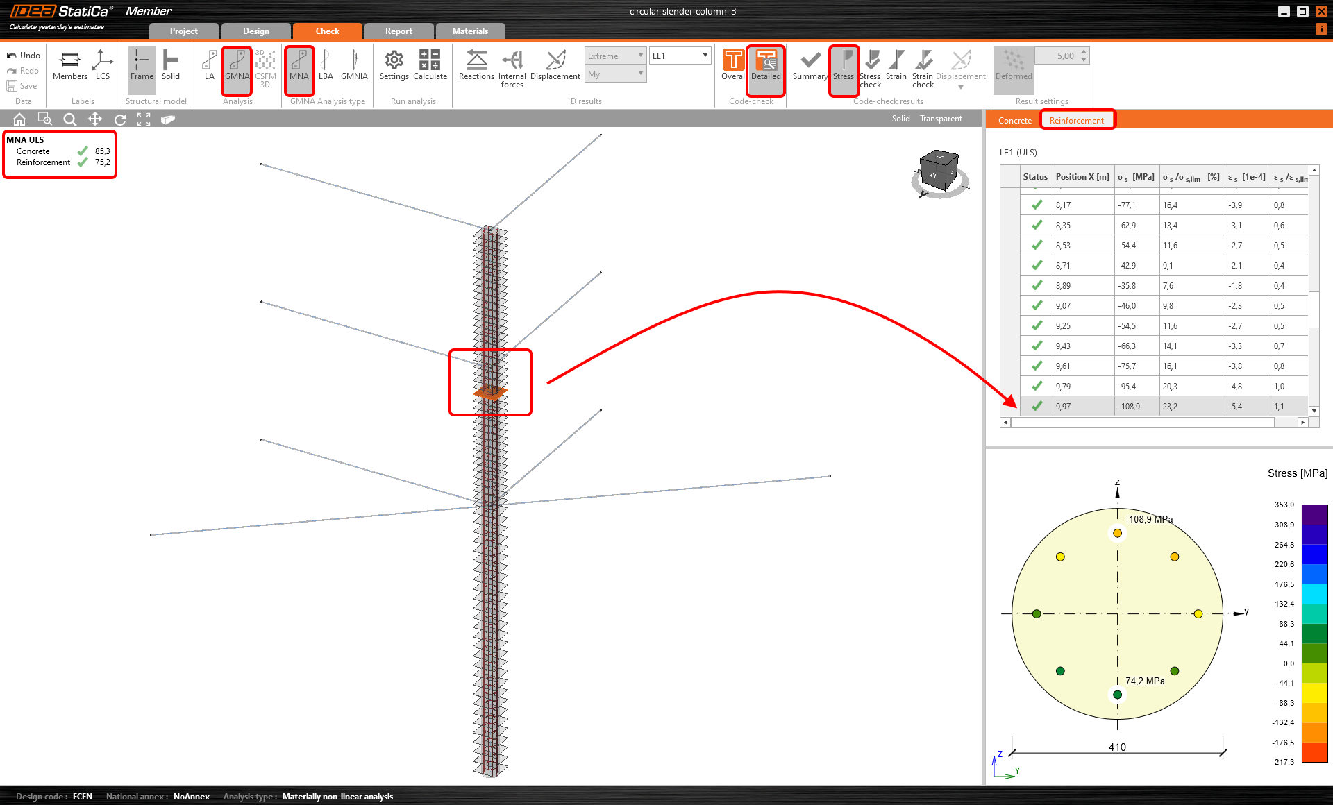
Per prima cosa viene eseguita l'analisi materialmente non lineare (MNA). Se non è necessario considerare la non linearità geometrica e le imperfezioni, ci si può fermare qui e la progettazione è completata. I valori forniti (tensione e deformazione) vengono quindi confrontati con i valori limite definiti dalla normativa. I risultati dettagliati della singola fibra di calcestruzzo e della barra di armatura sono presentati graficamente per la sezione trasversale selezionata ed elencati nella tabella con tutti i valori corrispondenti di tensione e deformazione. È possibile verificare i risultati separatamente per il calcestruzzo e per l'armatura.

Se non è sufficiente considerare solo la non linearità materiale ed è necessario considerare anche quella geometrica, in tal caso è il momento di utilizzare l'analisi lineare di instabilità (LBA), i cui risultati sono le forme proprie e i carichi critici dell'elemento analizzato. Questa analisi aiuta l'ingegnere a determinare la perdita teorica di stabilità di una struttura soggetta ai carichi applicati.
Non sarebbe sicuro considerare solo la forma teorica di instabilità della struttura, poiché esistono imperfezioni iniziali. Per questo motivo la tabella dei risultati consente di definire l'ampiezza dell'imperfezione per ciascuna forma propria. L'imperfezione deve essere definita dall'ingegnere in base all'esperienza o alle raccomandazioni della normativa.
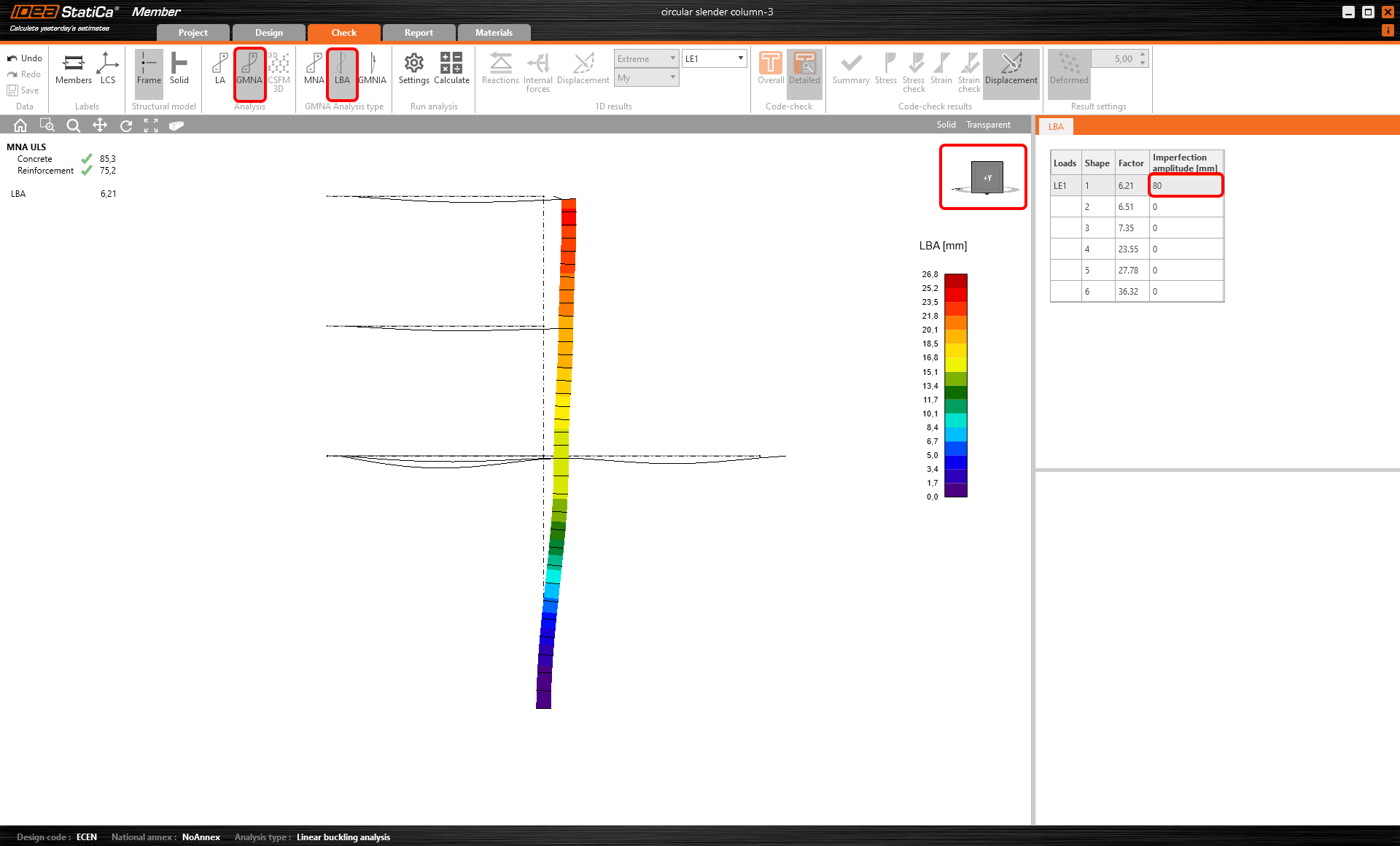
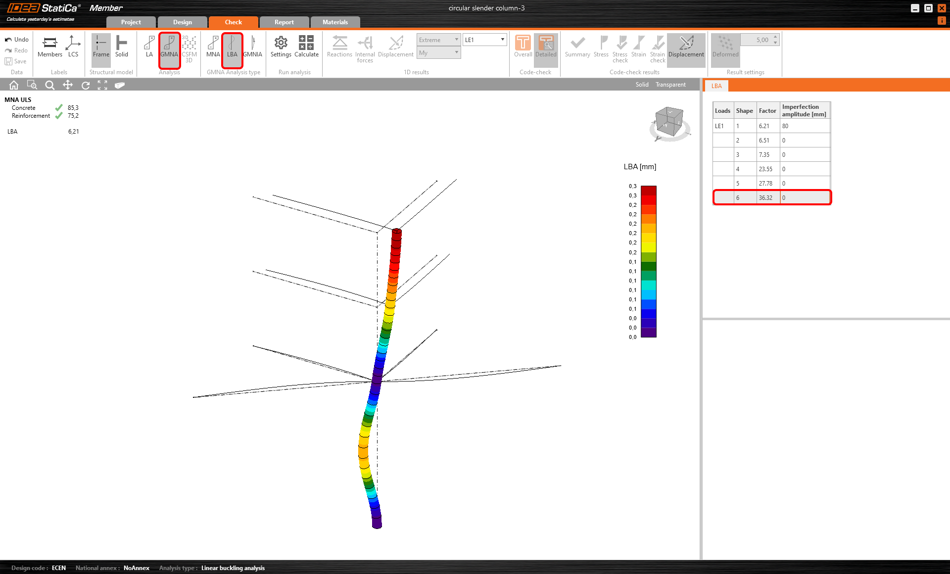
Fino a sei forme proprie sono i risultati dell'analisi lineare di instabilità (LBA).
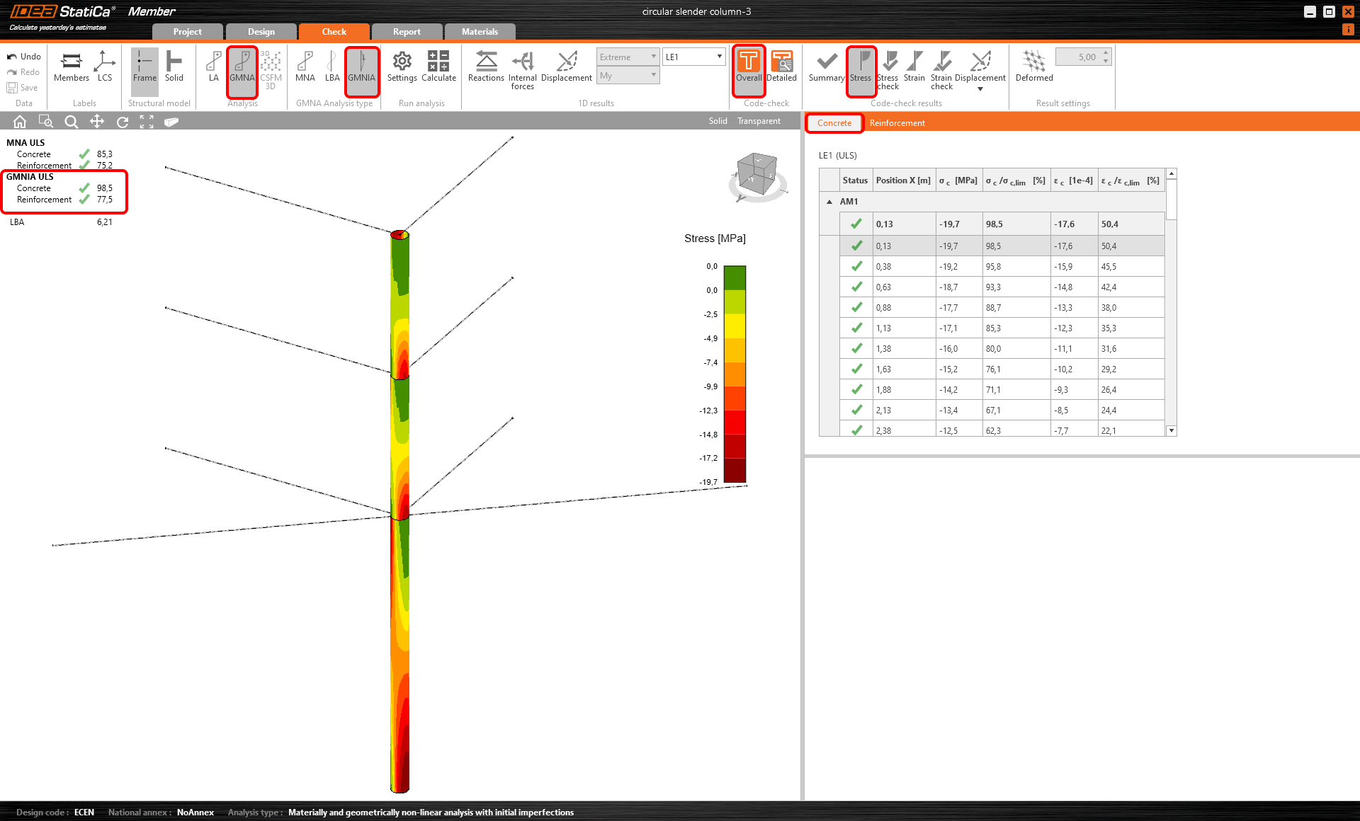
Una volta definita l'imperfezione, essa viene automaticamente applicata in modo proporzionale all'elemento, e quindi è possibile eseguire l'ultimo tipo di analisi – l'analisi geometricamente e materialmente non lineare con imperfezioni (GMNIA).
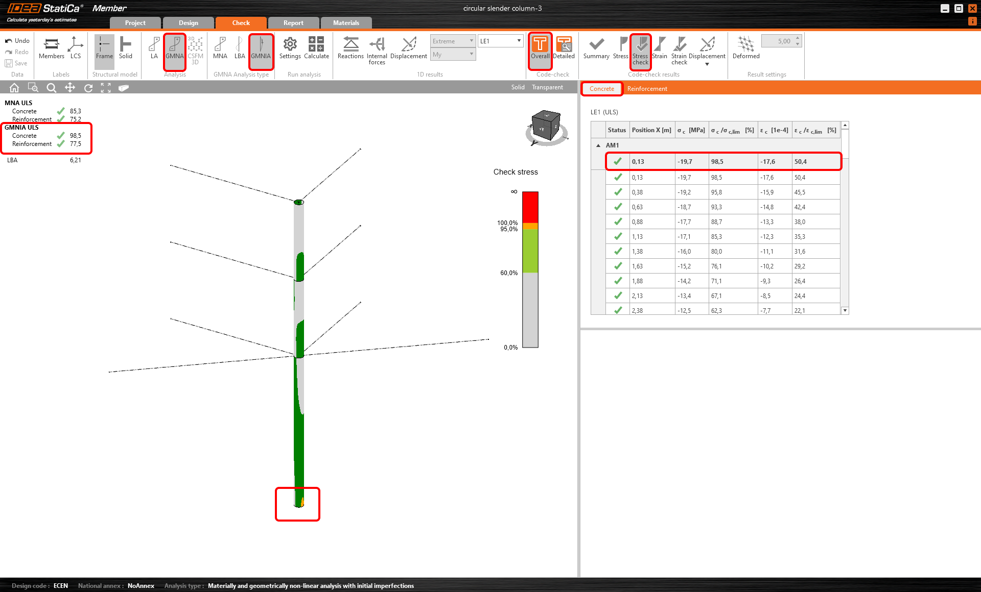
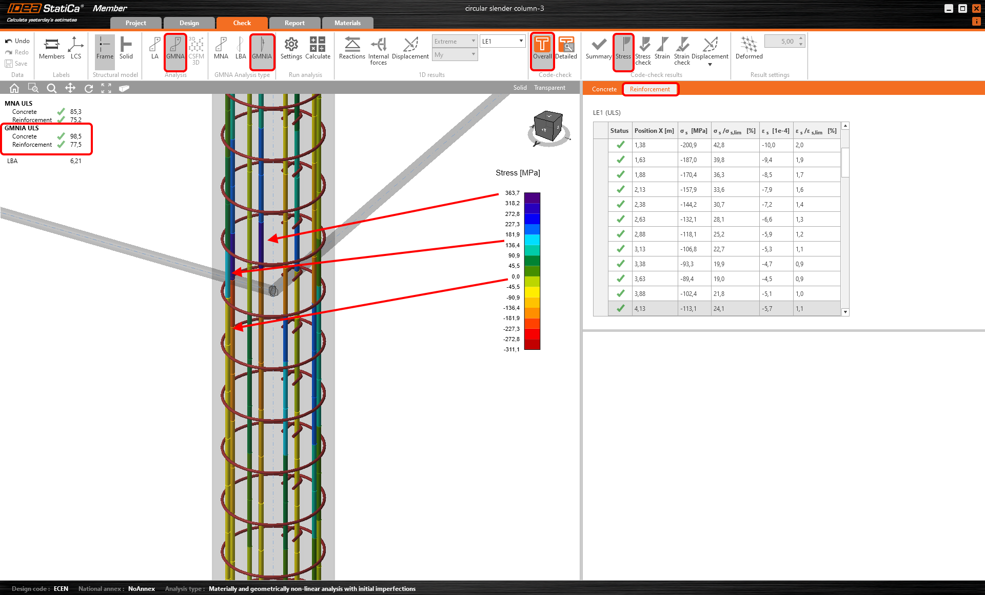
Con questa analisi si tengono in conto tutte le fonti di non linearità, come quelle materiali e geometriche, incluse le imperfezioni. I valori di output dell'analisi GMNA sono nuovamente tensioni e deformazioni nelle singole sezioni trasversali.
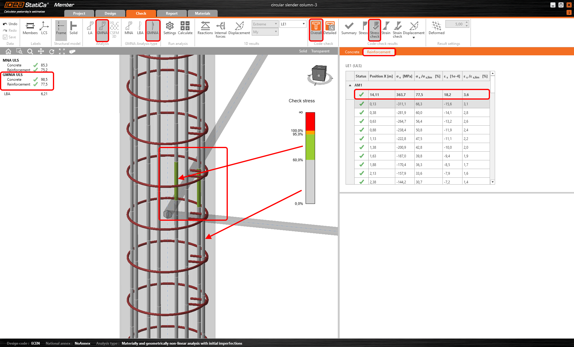
La verifica si basa sul confronto con i valori limite definiti dalla normativa. È possibile osservare i risultati dettagliati o complessivi, sia per le parti in calcestruzzo che per quelle di armatura. Nella barra multifunzione dei risultati della verifica normativa è possibile passare tra i valori di output di tensione, deformazione e freccia e le relative verifiche normative.
Esempio pratico
Si immagini una struttura globale in SCIA Engineer. È necessario fornire una progettazione sicura ed economica di tale edificio. La parte problematica riguarda come definire le lunghezze di instabilità di una colonna la cui altezza è pari all'altezza totale dell'edificio (14,2 m) e come tenere conto di tutte le possibili non linearità, poiché la stabilità avrà un ruolo significativo nella progettazione di un elemento così snello.
Il flusso di lavoro potrebbe essere il seguente:
- Creare il modello globale della struttura in SCIA Engineer
- Definire i casi di carico e le combinazioni ed eseguire l'analisi lineare globale in SCIA Engineer
- Utilizzare il collegamento BIM tra SCIA Engineer e IDEA StatiCa tramite cui si importano la geometria, i carichi e i risultati
- Importare l'intera struttura tramite file SAF nell'applicazione IDEA StatiCa Checkbot, dove si definisce l'elemento analizzato (colonna snella) e si selezionano le combinazioni critiche
- Avvio dell'elemento analizzato (colonna snella) in IDEA StatiCa Member
- Verifica della correttezza dell'importazione - geometria e carichi
- Progettare l'armatura della colonna
- Eseguire tutti i tipi di analisi non lineari (MNA, LBA, GMNIA)
- Ottimizzare la geometria della colonna o l'armatura
- Stampare il report di calcolo con tutti i risultati importanti, le verifiche normative e le figure


Esperienza utente
Testa la nuova funzionalità e dicci la tua opinione. Scarica liberamente il file zip allegato e provalo tu stesso.
Vorresti migliorare qualcosa? Ci farebbe molto piacere ricevere il tuo feedback.
Come si può notare, le verifiche non dipendono dalla normativa nel senso di varie formule o flussi di lavoro profondamente integrati raccomandati dalla normativa, ma sono piuttosto conformi alla normativa nel senso che utilizzano i valori limite di tensione e deformazione definiti dalla normativa, nel calcestruzzo e nell'armatura. Finora è stato implementato l'Eurocode. Sei interessato all'implementazione di altre normative? Faccelo sapere!