Progettazione del collegamento trave in acciaio-calcestruzzo
L'uso misto di materiali nell'ingegneria strutturale è molto comune. Può essere legato a un ampliamento edilizio, a una riparazione, a un cambio di destinazione d'uso, ecc. In questo caso, parleremo di acciaio e calcestruzzo. L'integrazione delle applicazioni IDEA StatiCa ci aiuta a progettare dettagli strutturali che combinano entrambi i materiali.
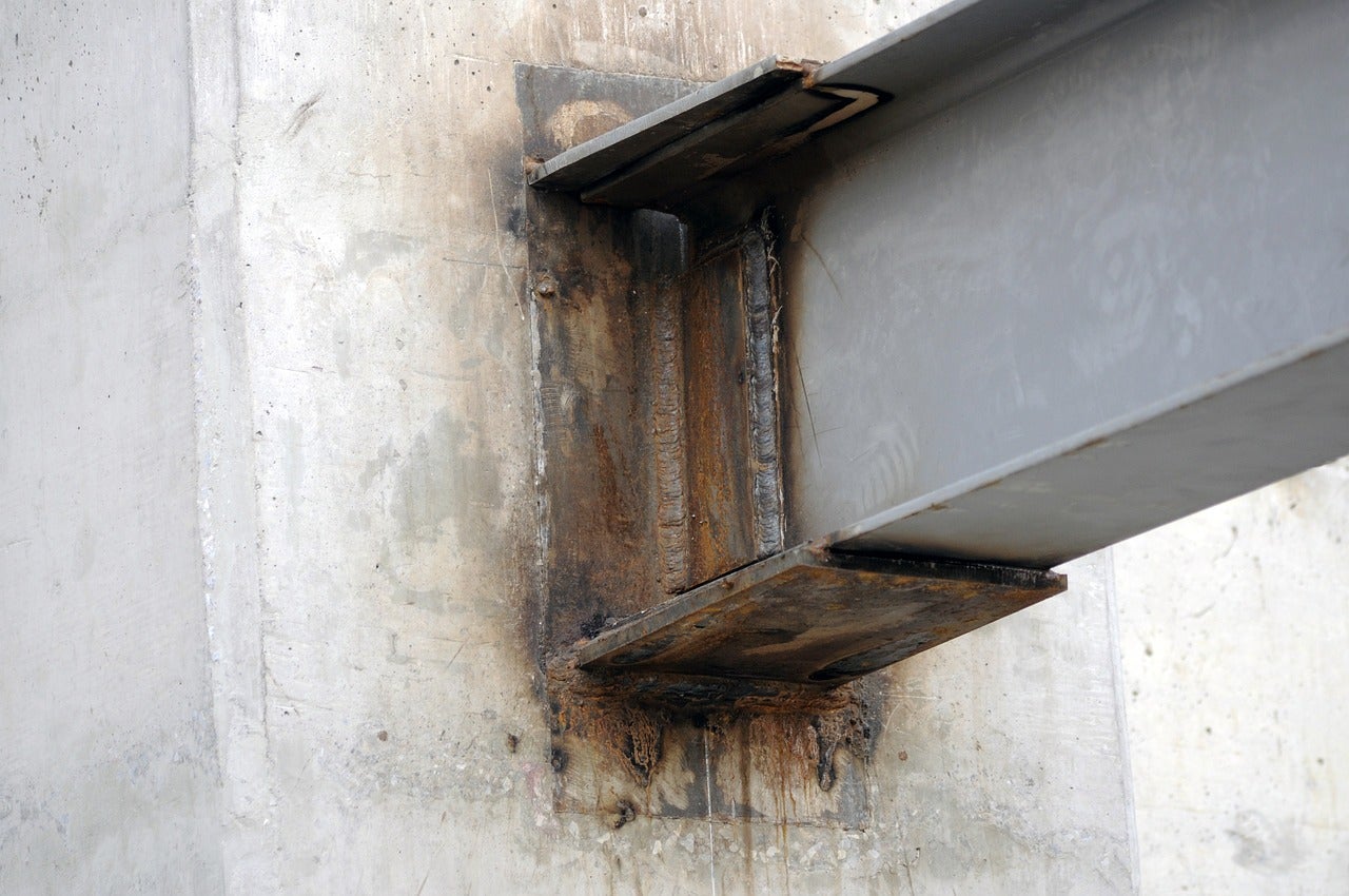
Un caso tipico è il giunto trave in acciaio-struttura in calcestruzzo. La sfida in questo caso d'uso è come trasferire le forze di taglio o di momento nella parete/trave/colonna in calcestruzzo e verificare che l'armatura progettata possa assorbire le forze. Se ciò non è possibile, è necessaria un'armatura di ancoraggio. Un'altra sfida è la progettazione della chiavetta a taglio utilizzata per trasferire la forza di taglio. Ecco come è possibile risolvere questo dettaglio ingegneristico:
Connection
In IDEA StatiCa Connection, è possibile modellare e progettare gli elementi in acciaio, le piastre e gli ancoraggi su un elemento in calcestruzzo orientato verticalmente.
Esaminiamo le opzioni disponibili.
Nell'applicazione Connection, le operazioni di piastra di base e griglia offrono la possibilità di aggiungere un blocco in calcestruzzo. Generalmente, l'operazione di piastra di base viene utilizzata per le piastre di base delle colonne, ma può essere utilizzata anche per un orientamento a trave. Di seguito è illustrato il processo:
Suggerimento: Modificare l'orientamento della piastra di base. Se la trave è inclinata, cambiare l'orientamento su Verticale.
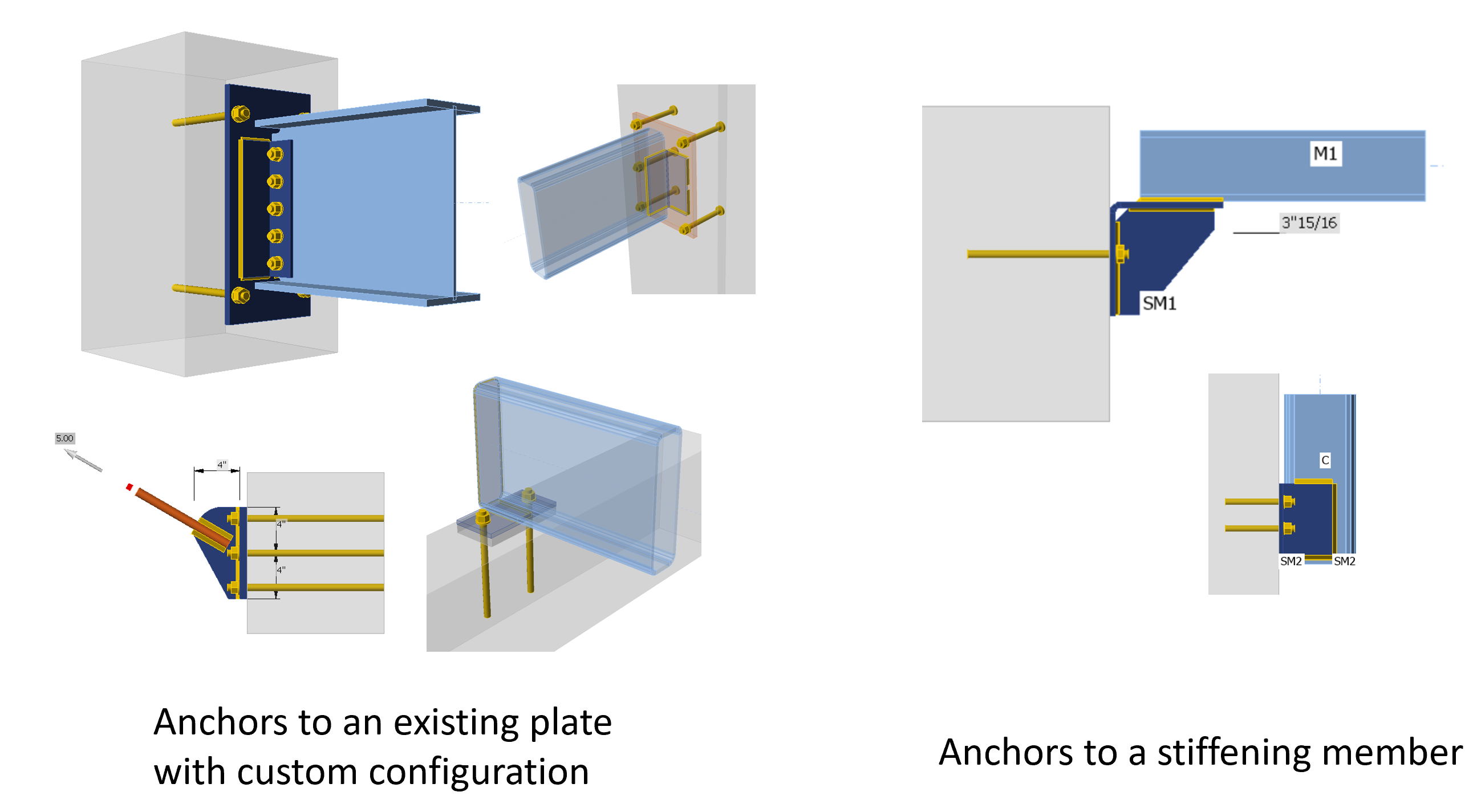
L'operazione di griglia consente di aggiungere ancoraggi a qualsiasi piastra nel modello; in questo caso è consigliata quando è necessario modellare un collegamento personalizzato da una trave in acciaio a un blocco in calcestruzzo. Come nei seguenti casi:
È possibile approfondire i suggerimenti di modellazione nei webinar registrati:
- Semplificare i collegamenti acciaio-calcestruzzo
- Progettazione di collegamenti acciaio-calcestruzzo, incluse le piastre di base
In IDEA StatiCa Connection, si eseguirà la verifica normativa di:
- Piastre in acciaio
- Bulloni
- Saldature
- Ancoraggi, chiavette a taglio
- Rottura del calcestruzzo, pryout, side face blowout, ecc. (utilizzando le formule empiriche ACI)
Per gli ancoraggi, alcune modalità di rottura non possono essere verificate in Connection perché il blocco in calcestruzzo è considerato non armato. Per ulteriori informazioni, consultare qui.
Detail 3D
Dopo aver progettato il componente in acciaio, esportare il modello in Detail 3D per progettare l'armatura in calcestruzzo. Per esportare il modello, utilizzare l'icona nella scheda Verifica all'interno della scheda Connection; verrà creato un file.
In Detail 3D, il modello contiene le piastre, i carichi, gli ancoraggi e il blocco in calcestruzzo dall'applicazione Connection. Tuttavia, l'utente deve modellare le barre di armatura nel blocco in calcestruzzo, che può essere simulato come una parete, una colonna, una trave, ecc., garantendo la corretta disposizione dell'armatura in acciaio richiesta dalla normativa.
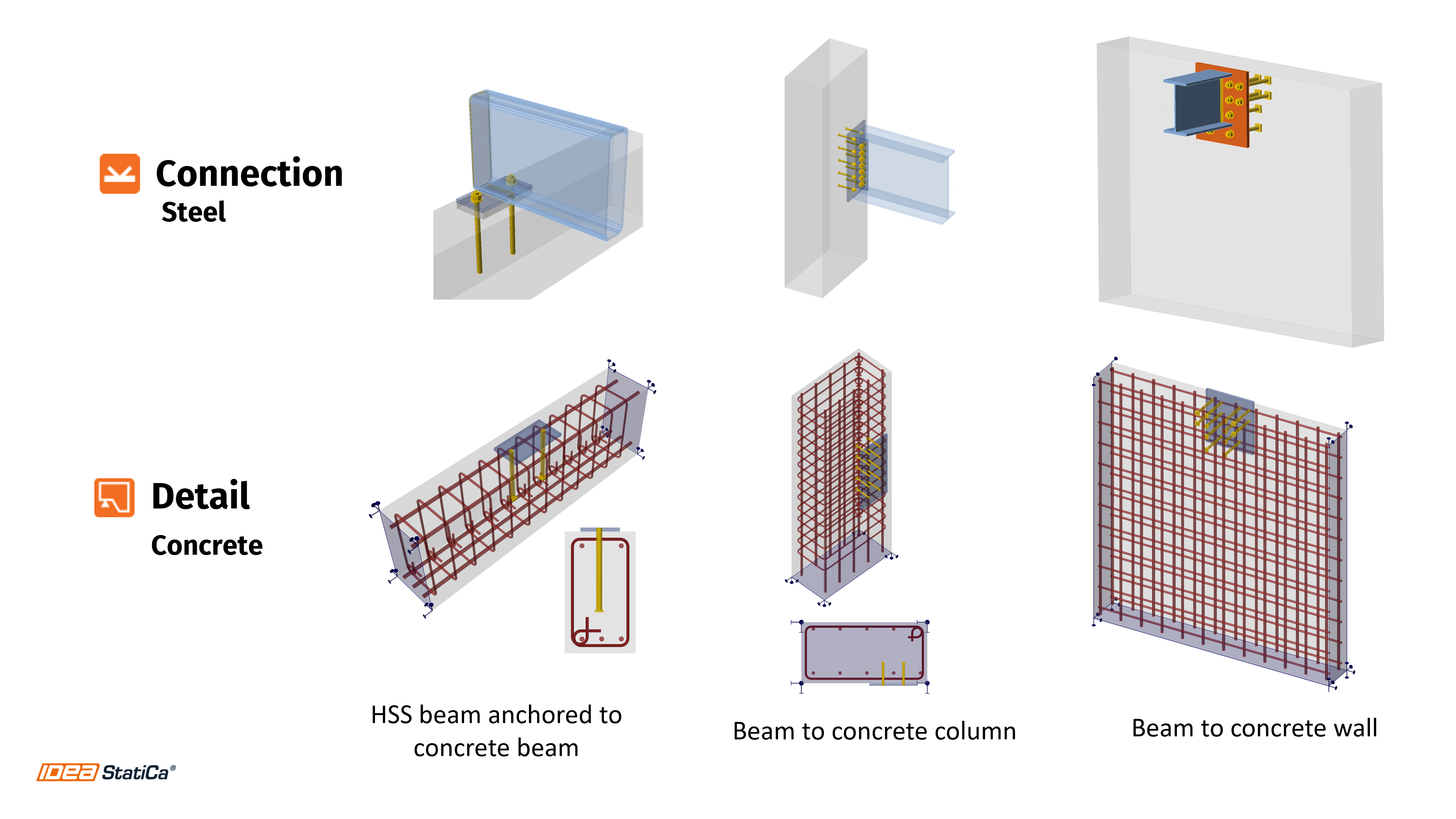
Di seguito sono riportati esempi di giunti che possono essere analizzati:
Hai avuto casi simili?
Risparmia tempo e riduci gli errori trasferendo i dati strutturali tra Connection e Detail senza la necessità di reinserimento manuale. Prova a integrare i due potenti strumenti e migliora la produttività del tuo team con flussi di lavoro automatizzati per la progettazione di collegamenti acciaio-calcestruzzo.

Prova IDEA StatiCa gratuitamente
Contenuti correlati
Verifica normativa completa di ancoraggi e blocco in calcestruzzo in Detail 3D (ACI)