Steel beam-to-concrete connection design
The mixed use of materials in structural engineering is very common. It can be related to a building expansion, repair, change of use, etc. In this case, we will talk about steel and concrete. The integration of IDEA StatiCa applications helps us to design structural details combining both materials.
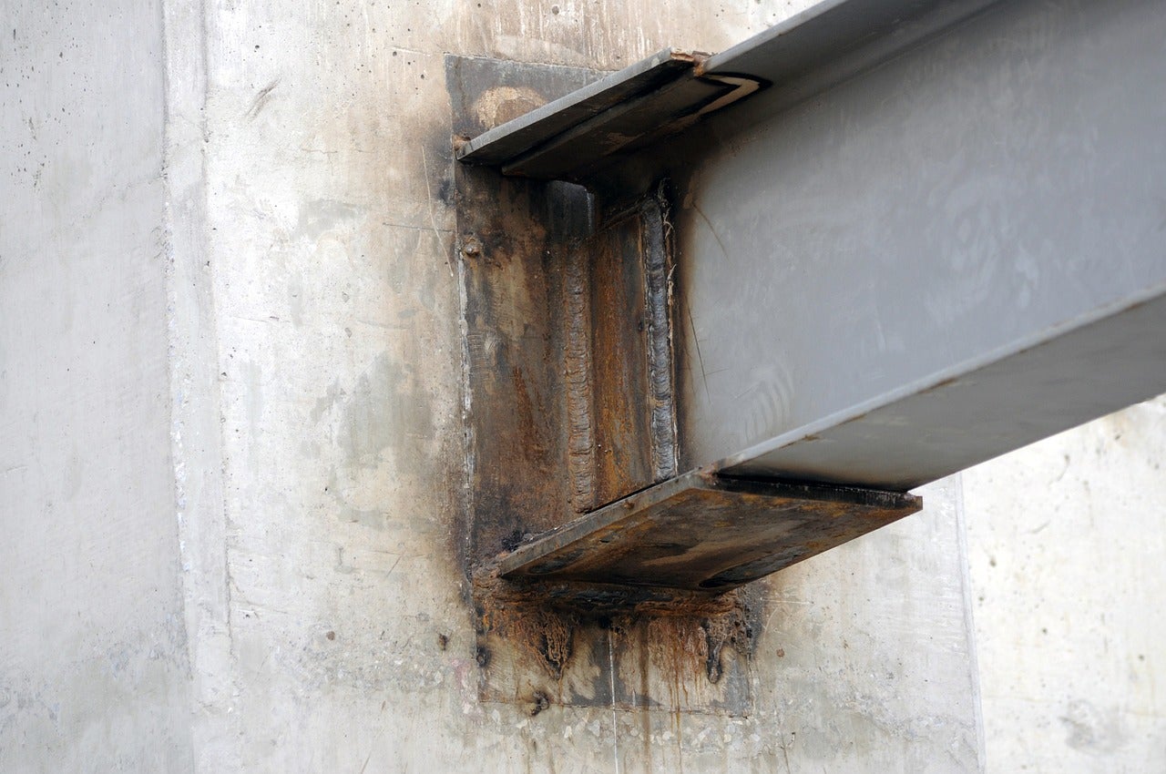
A typical case is the steel beam-to-concrete structure joint. The challenge in this use case is how to transfer either shear or moment forces into the concrete wall/beam/column and verify that the designed reinforcement can take the forces. If that is not the case, then anchor reinforcement is needed. Another challenge is the shear lug design used to transfer the shear force. Let me show you how you can solve this engineering detail:
Connection
In IDEA StatiCa Connection, it is possible to model and design the steel members, plates, and anchors to a vertically oriented concrete element.
Let's review the options.
In the Connection app, the base plate and grid operations have the option to add a concrete block. Commonly, the base plate operation is used for column base plates, but you can also use it for a beam orientation. See below the process:
Pro tip: Change the orientation of the base plate. If the beam is sloped, change the orientation to Vertical.
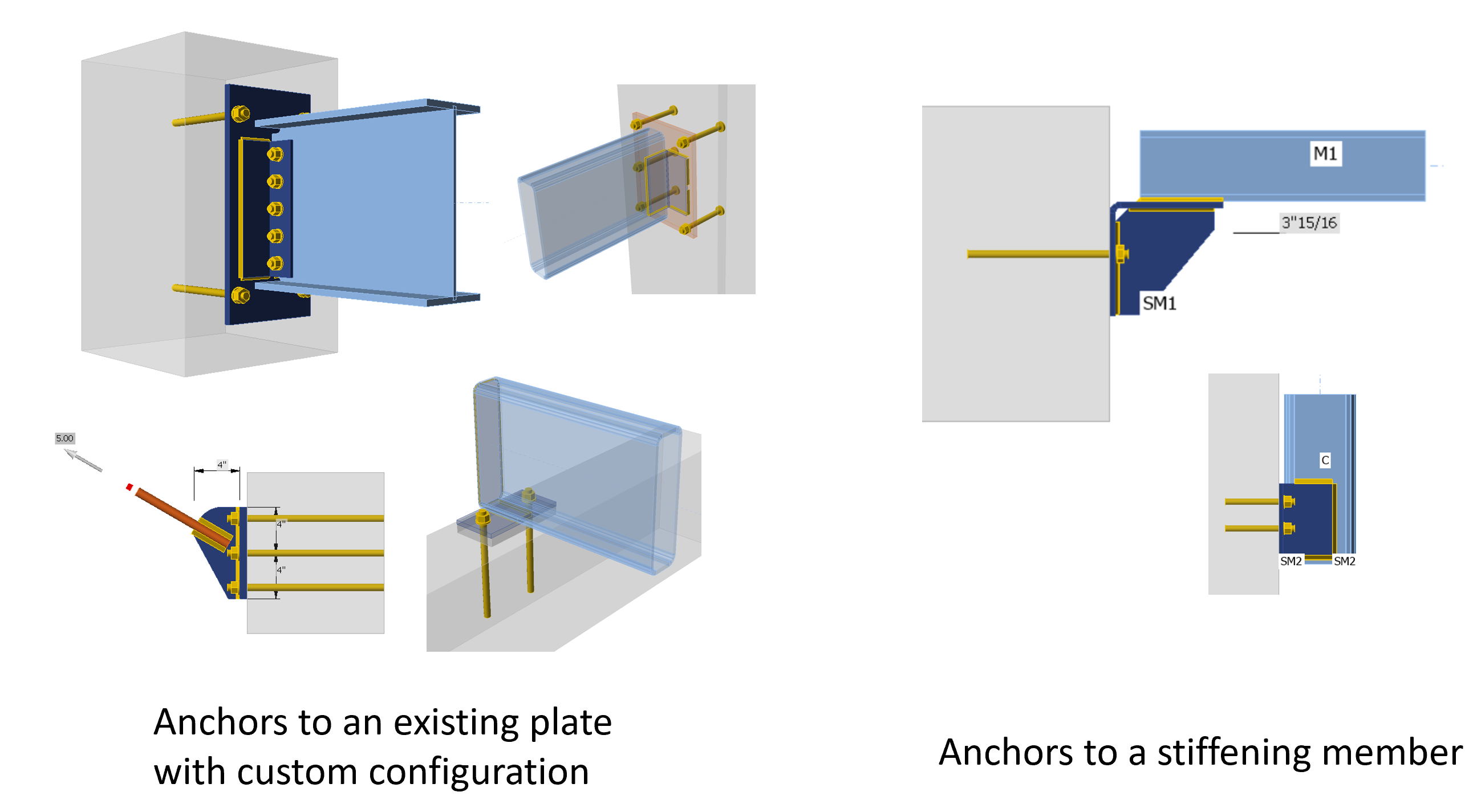
The grid operation helps you to add anchors to any plate in the model, so in this case, it is recommended when you have to model a custom connection design from a steel beam to a concrete block. Like the following cases:
You can learn more about modeling tips in the recorded webinars:
- Simplifying steel to concrete connections
- Design of Steel to Concrete Connections, including Base Plates
In IDEA StatiCa Connection, you will code-check:
- Steel plates
- Bolts
- Welds
- Anchors, shear lugs
- Concrete breakout, pryout, side face blowout, etc.(using empirical ACI formulas)
For anchors, some failure modes cannot be checked in Connection because the concrete block is considered unreinforced. Read more about it here.
Detail 3D
After designing the steel component, export the model to Detail 3D to design the concrete reinforcement. To export the model, use the icon under the Check tab in the Connection tab, and a file will be created.
Now, in Detail 3D, the model contains the plates, loads, anchors, and concrete block from the Connection app. However, the user should model the rebar in the concrete block, which can be simulated as a wall, column, beam, etc., ensuring the correct detailing of the steel reinforcement required by the code.
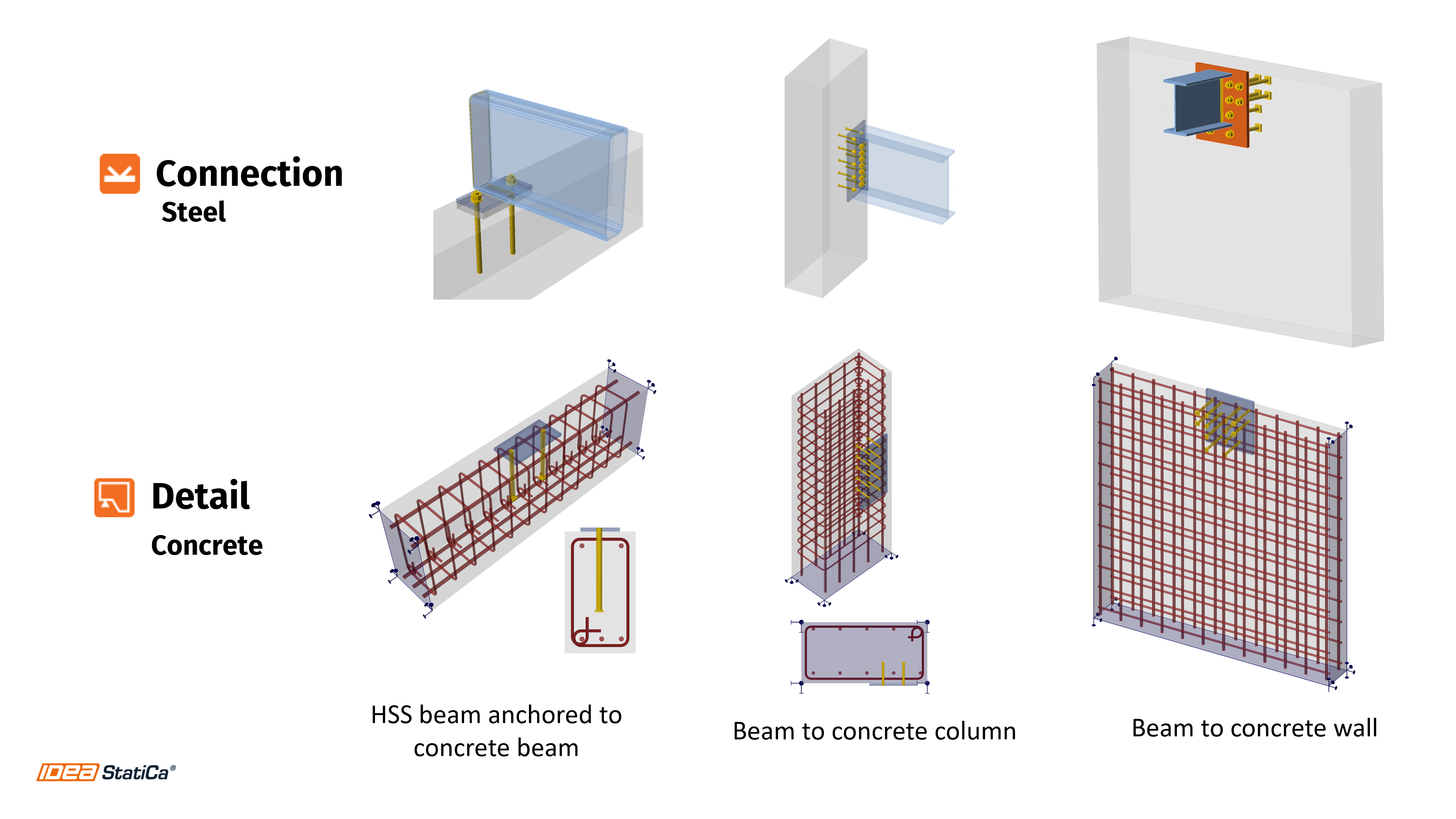
Here are examples of joints that can be analyzed:
Have you had similar cases?
Save time and reduce errors by transferring structural data between Connection and Detail without the need for manual re-entry. Try integrating the two powerful tools and improve your team's productivity with automated workflows for designing steel-to-concrete connections.

Testen Sie IDEA StatiCa kostenlos
Related content
Complete code-check of anchors and concrete block in Detail 3D (ACI)