Bulloni nel CBFEM
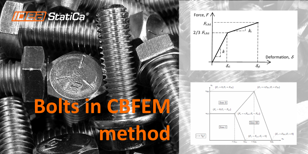
Nel Metodo degli Elementi Finiti basato sui Componenti (CBFEM), il bullone con il suo comportamento a trazione, taglio e rifollamento è il componente descritto da molle non lineari dipendenti. Il bullone a trazione è descritto da una molla con la sua rigidezza assiale iniziale, la resistenza di progetto, l'inizializzazione dello snervamento e la capacità di deformazione. La rigidezza assiale iniziale è derivata analiticamente nella linea guida VDI2230.
Solo la forza di compressione viene trasferita dal gambo del bullone alla piastra nel foro del bullone. Essa è modellata tramite collegamenti di interpolazione tra i nodi del gambo e i nodi del bordo del foro. La rigidezza di deformazione dell'elemento shell che modella le piastre distribuisce le forze tra i bulloni e simula il rifollamento adeguato della piastra. I fori dei bulloni sono considerati standard (predefiniti) o assolati (impostabile nell'editor della piastra). I bulloni nei fori standard possono trasferire la forza di taglio in tutte le direzioni, i bulloni nei fori assolati hanno una direzione esclusa e possono muoversi liberamente in questa direzione selezionata. L'interazione tra la forza assiale e la forza di taglio può essere introdotta direttamente nel modello di analisi. La distribuzione delle forze riflette meglio la realtà (vedere il diagramma allegato). I bulloni con un'elevata forza di trazione assorbono una minore forza di taglio e viceversa.
Puoi leggere ulteriori informazioni sui bulloni o sul metodo CBFEM nel nostro documento Theoretical Background.