
BIM – La risposta a tutte le nostre preghiere (di ingegneria strutturale)?
Il Building Information Modeling (BIM) è con noi da oltre un decennio, eppure viene ancora visto, più spesso di quanto vorremmo, come un ostacolo a un lavoro efficiente. Ci sono diverse ragioni dietro questa osservazione, ma principalmente perché ho ascoltato e visto come lavorano molti ingegneri e come cooperano con gli altri.
Oltre dieci anni fa, ho proposto che esistessero tre tipi di modellazione:
- Modellazione per la documentazione
- Modellazione per l'analisi e la progettazione
- Modellazione per la costruzione
Il primo di questi è quello con cui molti sostenitori del BIM strutturale si trovano a proprio agio e molti concordano che abbia ottimizzato il loro lavoro.
Tuttavia, nonostante le vaste risorse dei principali fornitori, non molti stanno integrando il modello geometrico con un modello analitico. I vantaggi da ottenere, se questo viene utilizzato, sono enormi.
Il terzo livello si raggiunge quando il modello strutturale viene sviluppato ulteriormente in modo da riflettere non solo COSA verrà costruito, ma COME verrà costruito. Sono ancora meno gli ingegneri che arrivano a questo punto e quelli che ci riescono di solito lavorano a stretto contatto con l'appaltatore principale.
Per questo articolo, mi concentrerò sulla seconda fase, poiché sono sicuro che la prima sia stata trattata più e più volte. La terza fase sarà un argomento per un altro giorno, ma basti dire che l'evoluzione del modello è lineare e le informazioni non dovrebbero andare perse, ma ampliate e sviluppate.
Quale approccio dovrebbero seguire gli ingegneri?
Esistono molti approcci per integrare il modello analitico strutturale con quello geometrico. In generale, gli approcci rientrano in tre categorie: diretto, basato su file e middleware.
Un esempio sia dell'approccio diretto che di quello basato su file è Autodesk Revit, che combina un modello analitico e uno geometrico. Tekla Structures si integra tramite trasferimento di file. La novità nel settore è del Gruppo Nemetschek con una soluzione middleware basata su cloud - SCIA AutoConverter - che ha introdotto un nuovo formato di file (SAF) basato su Microsoft Excel.
Tutti hanno i loro pregi, insidie e svantaggi. Qualunque percorso venga scelto, è fondamentale che il flusso di lavoro sia compreso, altrimenti l'approccio diventerà rapidamente un prodotto inutilizzato.
Ancora una volta, l'ho visto molte volte!
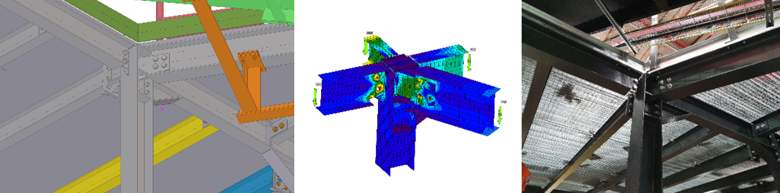
Se la progettazione dei collegamenti deve diventare parte integrante del processo BIM in modo efficace, deve essere sufficientemente flessibile da adattarsi a qualsiasi approccio. L'azienda per cui lavoro – IDEA StatiCa – ha una soluzione che esegue la verifica normativa dei collegamenti in acciaio (tra le altre soluzioni) utilizzando una tecnologia chiamata Checkbot.
Checkbot soddisfa i requisiti per la modellazione ai fini dell'analisi, della progettazione E della costruzione. La tecnologia è stata progettata per essere flessibile, con il potenziale di unire i flussi di lavoro in futuro.
Requisiti per la progettazione dei collegamenti
Gli ingegneri che si occupano della progettazione dei collegamenti sono una derivazione del processo di progettazione strutturale, senza la quale però il telaio in acciaio non reggerebbe. Dove viene considerata la progettazione dei collegamenti nel flusso di lavoro? Di solito verso la fine della progettazione. Quale elemento in acciaio raggiunge per primo una fondazione? Un collegamento con piastra di base.
In passato, i progettisti di collegamenti hanno fatto affidamento sull'ingegnere che forniva loro le informazioni necessarie tramite disegni annotati. Molto spesso le forze trasmesse non avevano alcuna somiglianza con le combinazioni di carico utilizzate per la verifica normativa degli elementi effettivi.
Devo ammettere che anch'io ero uno di quelli. Avevo pensato che i giorni in cui si usava il momento massimo con il taglio massimo e lo sforzo assiale massimo (tutti arrotondati al 25 kN/kNm più vicino) fossero finiti. Ma purtroppo non è così.
I progettisti di collegamenti richiedono gli stessi risultati di combinazione per garantire che il collegamento regga a TUTTE le possibilità, non a un caso peggiore presunto. Tuttavia, è ovvio che documentare ogni risultato di combinazione di carico per ogni elemento in un collegamento è irto di pericoli: esiste un rischio aggiuntivo che i valori (e il segno) possano essere errati.
Alcune soluzioni possono esportare su un foglio di calcolo come Microsoft Excel, ma anche questo approccio richiederà una certa preparazione dei dati per ottenere i dati nel formato corretto.
Il nostro approccio
In IDEA StatiCa, abbiamo sviluppato una serie di BIM Link (utilizzando Checkbot) che collegano la nostra soluzione di progettazione dei collegamenti con un ecosistema di soluzioni FEA e BIM (CAD). Alcuni dei nostri partner hanno anche sviluppato collegamenti dalle loro soluzioni FEA e BIM a IDEA StatiCa utilizzando il nostro IOM (IDEA Open Model).
Questa metodologia consente la condivisione delle informazioni e riduce il rischio di errori con un enorme aumento dell'efficienza. Per un ingegnere, la condivisione del modello è molto più di un semplice modello geometrico.
Ma se un modello di analisi deve essere condiviso, deve anche essere corretto e calcolabile.
Cosa intendo per calcolabile?
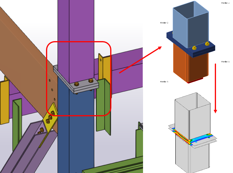
Prima di tutto, deve assemblarsi correttamente senza nodi "flottanti". Gli elementi devono connettersi ai nodi corretti. Può essere un modello semplificato (agli ingegneri piace semplificare le cose) con diversi elementi che si incontrano in un nodo designato quando in realtà non lo fanno. Gli elementi devono essere nel piano corretto e non distorti perché le ipotesi di allineamento sono errate. Dovrebbe inoltre esserci un equilibrio delle forze, che dovrebbe essere ottenuto idealmente direttamente dai risultati dell'analisi.
Ma cosa succede se abbiamo sia il modello geometrico che il modello di analisi (possibilmente da ingegneri diversi)? Esiste un approccio ibrido che possiamo sfruttare, mediante il quale possiamo creare due progetti in IDEA StatiCa utilizzando la geometria dell'uno e i risultati dell'analisi dell'altro. Questo è l'approccio del modello unificato. Richiede tuttavia che entrambe le parti abbiano modelli sincronizzati con gli elementi corretti nelle posizioni corrette.
Conclusioni
Quali sono le regole che gli ingegneri dovrebbero rispettare per un utilizzo efficace delle informazioni?
- Modelli coerenti per l'intero flusso di lavoro – elementi posizionati correttamente in tutti i modelli
- Modelli calcolabili – deve essere possibile eseguire un'analisi
- I materiali devono corrispondere alla regione ed essere coerenti in tutti i modelli
- Le dimensioni delle sezioni dovrebbero idealmente essere coerenti in tutti i modelli
- Evitare l'uso di sezioni speciali o composte o documentarle
- Lavorare insieme
Le informazioni che IDEA StatiCa crea costituiscono la base per la fase 3 – Modellazione per la costruzione, poiché alimenta il processo di fabbricazione, ma utilizza le informazioni sviluppate nelle fasi 1 e 2 per far avanzare la progettazione.
Non sto dicendo che l'intero settore sia così. Ci piace pensare di essere all'avanguardia e di non aver paura di provare cose nuove. Ma onestamente, sento ancora la stessa risposta alle sfide che circondano i flussi di lavoro esistenti: "perché è sempre stato fatto così…"
C'è molto di più che possiamo fare come settore per evitare sprechi di tempo e materiali, o per ridurre l'impronta di carbonio di un progetto.
E come ingegneri, possiamo aprire la strada. Queste non sono idee nuove.
Ti è piaciuto questo articolo? Non perdere argomenti simili!